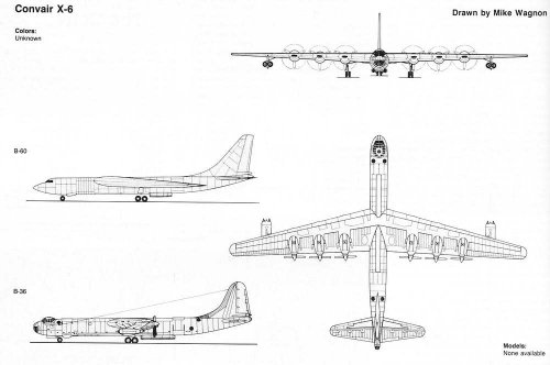
The 3-view drawing of the straight-wing X-6 (B-36) by Mike Wagnon, shown above, is inaccurate. Such an aircraft would have been modified to NB-36H standards, at the very least, to incorporate the heavily-shielded flight deck cocoon and its related structural reinforcement.
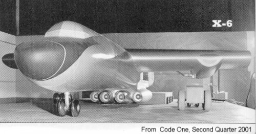
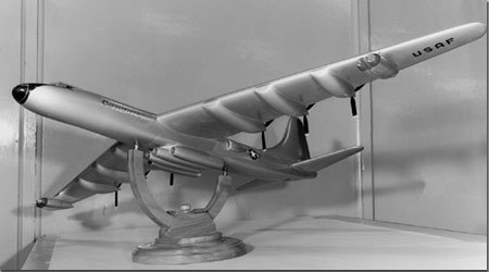
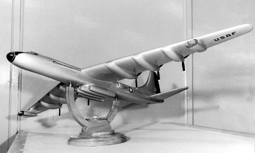
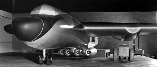
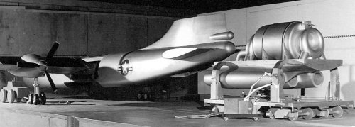
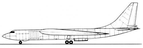
Also, the large heat exchanger inlets are missing and the X-39 engines are incorrectly located too far aft. The engines are also too small in diameter, too close to the fuselage and not staggered. All these modifications are clearly visible on the various X-6 manufacturer scale models. I fear that Wagnon's B-60-based X-6 drawing is similarly inaccurate, with its airliner-style cockpit.
The rest of the 3-view drawing looks excellent, so it must have been lifted from somewhere else.
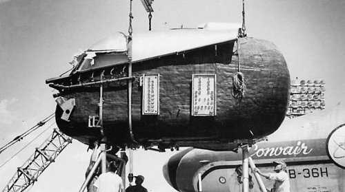
Attached photo shows lead-shielded flight deck being hoisted on the NB-36H, with instrumentation connector panels on side wall.