KJ_Lesnick
ACCESS: Top Secret
- Joined
- 13 February 2008
- Messages
- 1,042
- Reaction score
- 123
Was the F-8's inlet a single-shock inlet, or a multi-shock inlet?
KJ Lesnick
KJ Lesnick

KJ_Lesnick said:Was the F-8's inlet a single-shock inlet, or a multi-shock inlet?
KJ Lesnick
I vote for single shock if you don't count the normal shock.
Or two shocks counting the normal shock.
sferrin said:Now do the XF8U-3.")
KJ_Lesnick said:Shockonlip,
I vote for single shock if you don't count the normal shock.
Or two shocks counting the normal shock.
The normal shock counts, so it's a twin-shock inlet...
I got some questions
- Regarding the nose-cone diameter: Since you are unsure of the exact diameter of the nose cone, can you guesstimate a range of degrees the nose would be (in other words can you figure out how far off you could be?)? If it's not too much to ask that is...
- Did you factor in the fact that the inlet is wider than it is tall? Does this have any adverse or beneficial effects on your predictions?
KJ Lesnick
(I'm trying not to sponge or anything -- this isn't exactly information you can just find with a google search)
Indeed a twin or two shock inlet.
Since the compression is all outside here, it would then be considered an
external compression inlet.
No I didn't do any vertical width versus horizontal width compensation. I don't
think that is necessary for our purposes. Actually you only asked how many
shocks and I think we answered that.
KJ_Lesnick said:Shockonlip,
I vote for single shock if you don't count the normal shock.
Or two shocks counting the normal shock.
The normal shock counts, so it's a twin-shock inlet...
I got some questions
- Regarding the nose-cone diameter: Since you are unsure of the exact diameter of the nose cone, can you guesstimate a range of degrees the nose would be (in other words can you figure out how far off you could be?)? If it's not too much to ask that is...
- Did you factor in the fact that the inlet is wider than it is tall? Does this have any adverse or beneficial effects on your predictions?
KJ Lesnick
(I'm trying not to sponge or anything -- this isn't exactly information you can just find with a google search)
KJ_Lesnick said:shockonlip,
Indeed a twin or two shock inlet.
Since the compression is all outside here, it would then be considered an
external compression inlet.
Really? I would have never known that. What advantages does an external compression inlet have over an internal compression inlet or a combination of internal and external compression?
No I didn't do any vertical width versus horizontal width compensation. I don't
think that is necessary for our purposes. Actually you only asked how many
shocks and I think we answered that.
Still it doesn't seem to be all that crazy a question when you think about it.
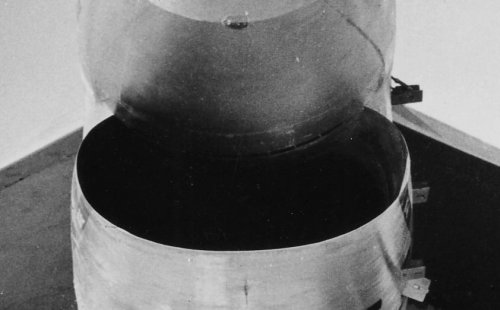
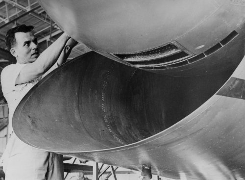
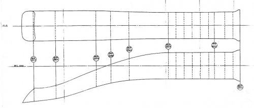
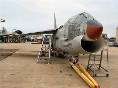
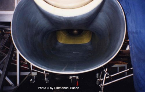
While I'm at it: I was looking at a picture of an F-8's inlet duct and I noticed some things. The nose-cone seems to continue deep inside the inlet-duct. I'm not sure if the shape of the duct is straight at the entry to the duct or slightly divergent. Regardless it narrows down a bit down the length of the fuselage. I'm wondering if anybody has any diagrams of the inlet duct of the F-8 assuming it's not classified?
An inlet with a divergent entry generally suggests the airflow is subsonic past the inlet leading edge but there are exceptions to this rule. The XB-70's outer inlet wall does look divergent. However when you consider that the inlet shortens considerably and the shape of that wedge-splitter in the middle -- the area of the duct actually does progressively narrow as you go deep inside the duct. The point I'm getting at is that the change in duct area (the whole package) is also highly important. With the cone going deep inside the inlet I'm wondering if the straight or even divergent shape of the duct is more than compensated by the cone?
I'm just curious because past the "chin", the duct does seem to narrow down a bit as it goes down the length of the fuselage it would appear. Now granted the duct could be getting taller in height and such which would negate the narrowing in width (and this odd duct shaping could be done for a number of things including area ruling) but I'm not sure as I don't know what the inside of the inlet looks like...
KJ Lesnick
KJ_Lesnick said:I don't know if this could physically happen, but what would happen if the shock off the nose went into the duct?
Kendra
KJ_Lesnick said:SFerrin,
So it would be quite a loud bang eh?
KJ_Lesnick said:Did they specify what mach number this happened at?
KJ_Lesnick said:I just wanted to bring something up...
I was reading about the F-11F-1 and according to what was said about it, it could reach at least Mach 2 and altitudes of over 80,000 feet in testing. What I'm wondering is, how is it that the F8U Crusader outperformed it, yet was slower...
Honestly, I'm kind of confused here especially if a program which actually shows shockwave angles specifically limits the F8U to Mach 1.85
KJ Lesnick
No probs. Glad people are enjoying it. I was a bit worried about posting because these aren't strictly projects.From meory, Kuwait got E.E Lightnings in the end ?
And Peruvian Crusaders ? awesome.
Lots of food for alt history, thank you for sharing your discoveries.
Subic Bay and Clark AFB for startersWhy and Marcos deeply rotten Philippines got Crusaders in comparison with all these countries, is beyond me.
And then Mount Pinatubo wrecked them...Subic Bay and Clark AFB for startersWhy and Marcos deeply rotten Philippines got Crusaders in comparison with all these countries, is beyond me.
Yes, my immediate thought was the English Electric Lightning also Archibald!From meory, Kuwait got E.E Lightnings in the end ?
And Peruvian Crusaders ? awesome.
Lots of food for alt history, thank you for sharing your discoveries.
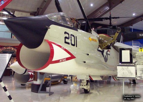
the statistics for the
F-8 Crusader, a supersonic fighter designed by Vought in the late 1950s, provide
a good illustration of the problem. The F-8 was always known as a difficult air-
plane to master. In all, 1,261 Crusaders were built. By the time it was withdrawn
from the fleet, 1,106 had been involved in mishaps. Only a handful of them (ok, 170 !) were
lost to enemy fire in Vietnam. While the F-8 statistics might have been worse
than those for most other models, they make the magnitude of the problem
clear: whether from engine failure, pilot error, weather, or bad luck, the vast ma-
jority (88 percent!) of Crusaders ever built ended up as smoking holes in the
ground, splashes in the water, or fireballs hurtling across a flight deck. This was
naval aviation from 1947 through about 1988.
Between 1949, the year jets started showing up in the fleet in numbers, and
1988, the year their combined mishap rate finally got down to Air Force levels,
the Navy and Marine Corps lost almost twelve thousand airplanes of all types
(helicopters, trainers, and patrol planes, in addition to jets) and over 8,500
aircrew
how long this
“transition” to jets lasted. Some histories of naval aviation regard the transition
to jets to be substantially complete with the phasing out of the last propeller-
driven fighter, the F4U Corsair, while others maintain that the transition lasted
until the introduction of the F-8 Crusader and F-4 Phantom II—the first Navy
carrier-based fighters that were the equals of their land-based counterparts. An-
other way of looking at it is through the lens of safety: one might declare the
transition to have been complete when the Navy aviation accident rate became
comparable to that of the U.S. Air Force. The logic behind this reasoning is that
whereas a multitude of factors—technical, organizational, and cultural—con-
stitute the capability to operate swept-wing jets, the mishap rate offers an overall
indicator of how successful an organization is in adopting a new technology.
Using this criterion, the Navy’s transition process lasted until the late
1980s—which was, not coincidentally, the era in which the F/A-18 arrived in
the fleet in numbers. This article argues that tactical jet aircraft design and
technology presented Navy aircrews, maintenance personnel, and leaders with
several major challenges that were in fact not substantially overcome until the
introduction of the F/A-18 Hornet in 1983.
All types losses in VN were high, AAA got quite a bit. The question to ask is how did it compare to other types. There's a great book from the 80's written by a Crusader driver, On Yankee Station, by Lt Commander Nichols. It covers this and a variety of Naval Aviation VN topics. The back has lots of stats just like what was asked.As to the F-8 losses in Nam, why were they so numerous? Was the lack of redundancy actually the main contributor?