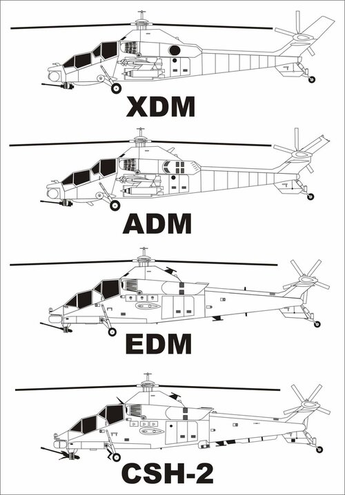
I'm trying and failing to get my head around the differences, serials, etc. of the Rooivalk XDM, the ADM and the EDM.
I think the XDM had the rounded bulged under-nose, extended tailfin, and sideways pointing exhausts, and that the EDM was the aircraft that wore the reg ZU-AHC, with a cropped tail, upward-pointing exhaust and the same original nose - or was that the ADM? If so, what was the EDM?
Here is a rather famous pic of the three prototypes:
In the front is EDM (oddly given the tail number 672 which was later awarded to a production version with its number changing to 682. The dummy nose is the give away as to its identity here), in the middle is ADM (notice no exhaust deflection) and at the top/back is XDM in more or less her final configuration. She was later back dated to lose the cheek fairing but retain the upturned exhaust.
XDM 683 was used for the airframe development work. As can be seen the tail was a major area of focus. Trevor Ralstone, program chief test pilot, apparently gave a very good lecture on it.
No exhaust deflection, large fin extention top and bottom Apache style deflection of exhaust gas, fin size decreased top and bottom. Final flight tested configuration. Up turned exhausts, cheek fairings and refined tail.
ADMZU-AHC largely shared the same airframe as XDM but was equiped with a fully functional weapons and avionic suite. XDM had a very basic cockpit layout with no MFDs and was only gun and unguided rocket capable. The development of the tail area to give the required control was already completed when ADM flew. She seems to have only flown with no exhaust and the apache style exhaust configuration, not the final design of an upturned exhaust.
EDM672/682 was the risk reduction step towards production. Based on the lessons from XDM and ADM the airframe was reduced in mass and redesigned based on what was tested on XDM and further refined. The sensor suite changed significantly to be largely based on proven French components rather than the more advanced, but unproven local developments. The aim was to eventually incorporate these in later upgrades.
Notice the dummy nose here and serial 672. EDM now fitted with a sensor nose same as what the Block 1A aircraft were delivered with. Renumbered as 682 she continues to be used as the development airframe for Denel.
Note The reason for the odd tail number ranges of XDM and EDM (ADM needed a non-type registration as she was on Denel register to travel the world for marketing I presume) are that they were allocated serials after the production run (SAAF tail number 670 to 681) was completed.
The Rooivalk fleet remains an engineering project owing to the very small production run of 12 airframes. There has been plenty refinements to the airframes over the years and the current standard in service with the SAAF is Block 1F. Denel and the SAAF use different terminology for the helicopter upgrade standard thus there is speak of CSH 1, Rooivalk Mk1 etc.
Production Rooivalk 677 in Block 1F standard. Credit to photographer.
Interestingly, Rooivalk was never formally offered to the UK. They were asked to review Rooivalk as it was hoped that would spark more international customers, and it did receive favourable comments from the evauation team, but it was always only the Apache the RAF wanted. Defence minister at the time, Joe Modise, was told it is official and made a public statement on it only to be soon corrected afterwards. He was not happy to look like a fool!
As my post above shows, XDM and ADM flew in a wide variety of configurations so cannot really be put down to a single configuration - particularly XDM.
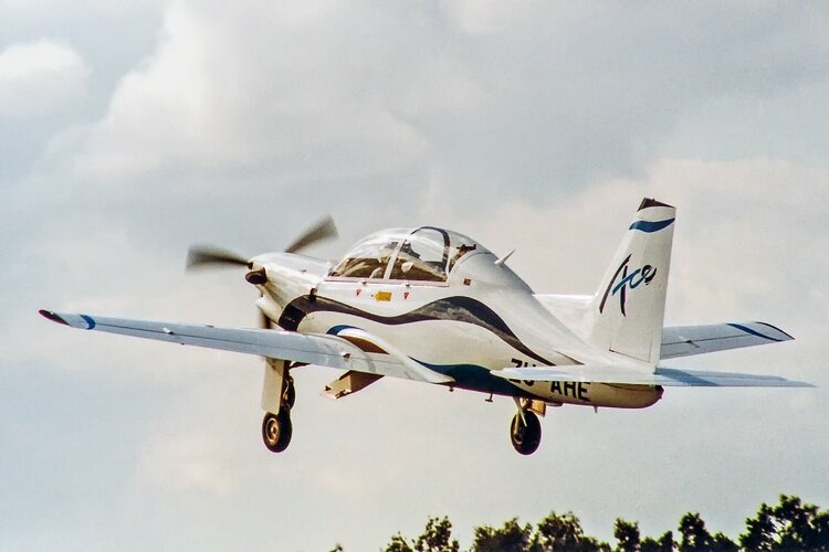
I think a while back on this thread, a poster stated he had video of the Atlas ACE/Ovid in flight.
I''ve looked around and realised there doesn't seem to be any available footage of the ACE in flight in the public domain, even though it flew at Farnborough 1994..
Anybody have any?
I think a while back on this thread, a poster stated he had video of the Atlas ACE/Ovid in flight.
I''ve looked around and realised there doesn't seem to be any available footage of the ACE in flight in the public domain, even though it flew at Farnborough 1994..
Anybody have any?
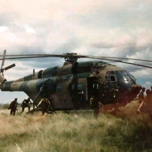
Post number 345 dealt with the Dakota turboprop programme modified into a genuine Maritime Patrol Aircraft.
The SAAF forum stated that along with the additional avionics, sonobuoys were also to be fitted.
Here are some clearer pics after that programme was cancelled, and one of the test aircraft sold.
Note that FLIR, and ventral radar radome.
The aircraft is still flying, albeit without the ventral radome.
This is the first time I have noticed this.
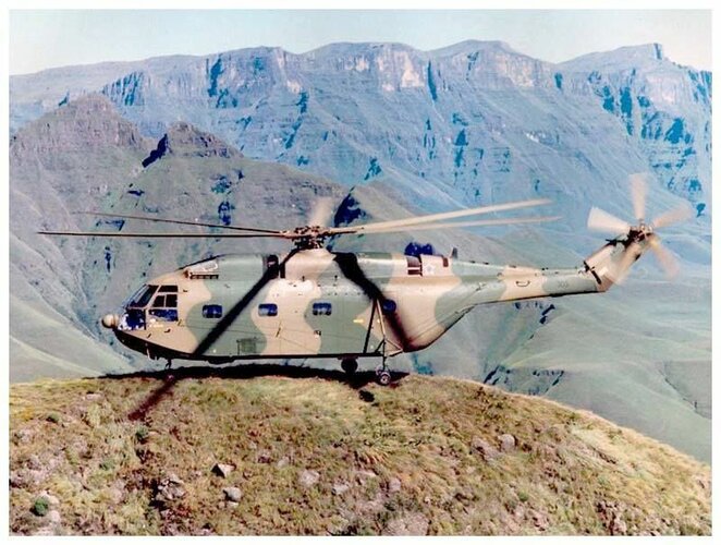
SAAF Super Frelon with a nose radar.
This radar installation is not the same as the French one, being more compact.
It seems to me to be the same as the Atlas Oryx nose radome/radar.
The Oryx stems from 1986 onwards, with the Super Frelon retired in 1990, after the cuts to the defence budget...so this seems to be in that time frame.
It points to a programme to upgrade and retain the Super Frelon, before the defence cuts and end of the Cold War.
Edit: First photo from the Drakensberg mountain range, which is high....so I wonder where this puts those reports of the SF not being great at high "hot and high".
Perhaps this was compared to the Puma, which was a good hot and high performer.
Remember the Drakensberg is high, but not very hot. Also I would venture that the Frelon in the picture is not carrying much cargo mass inside. The Drakensberg are a popular helicopter handling training area.
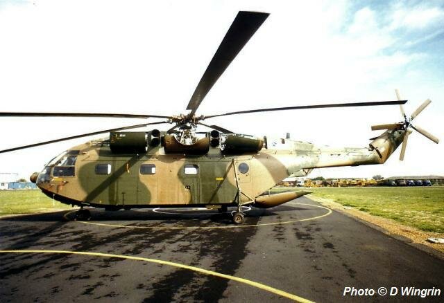
I recall hearing of a variety of upgrade proposals for the Frelon including changing the engines to the same Turbomeca Makila's as in the Oryx. Would have been much happier up high then! Few of them seemed to carry the weather radar though (none of the preserved ones have it) so I wonder if it was a perhaps lone airframe being tested? Pity the serial number is obscured in the second picture. Most likely the early demise put rest the idea of spending much effort on them.
Over on the SAAF forum, a technician posted in an older thread that radar was fitted to the Super Frelon whilst he was attached to 30 Sqn, at "the same time as the radar was fitted to the Puma".
30 Sqn Super Frelons were transferred to 15 Sqn in 1986.
1986 was also when the Atlas Oryx helicopter was being manufactured before being officially declared operational at the beginning of 1987.
The only Puma I am aware of fitted with radar was a Puma (177) that served as a prototype for some of the Oryx systems.
The picture I posted above of the Super Frelon with engine covers and cargo ramp open is from 1988 and taken at Ysterplaat AFB by Dean Wingrin from the SAAF forum.
So this seems to indicate a timeframe of the same period for this Super Frelon upgrade...1985-1986.
This would also dovetail neatly with the rumoured Makila re-engining project timewise with the Oryx programme.
A Makila engined Super Frelon would have increased available power by an extra 1500hp or so.
I have strongly suspected before South Africa had an eye on the Israeli Super Frelons as part of an upgrade programme with increased numbers.
The Israelis were using theirs less in this time frame as a result of recieving CH-53's.
I've posted some stuff on his V-TOL type jet aircraft development before in this thread - this is something much smaller - however with one firm order in place, this one should at least see the light of day..
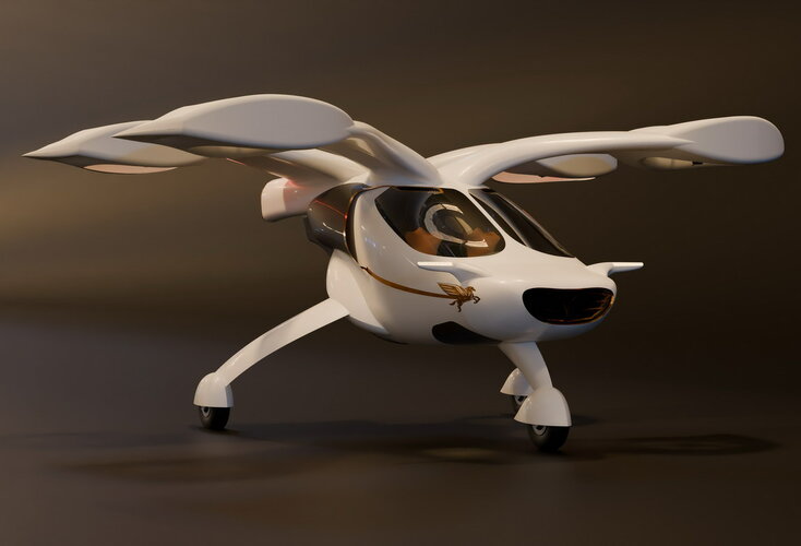
Pegasus Universal Airspace reveals two-man electric VTOL aircraft as part of new business model
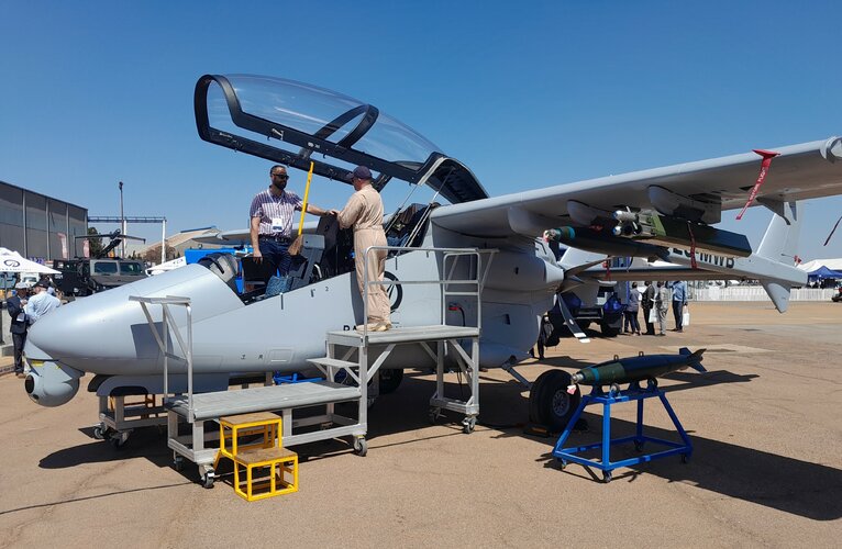
I had a quick chat with one of the Mwari Test Pilots (in brown flight suite) - He's a British pilot, came out from the UK about 9 months ago, Ex Tornado and Typhoon fighter pilot (IIRC his callsign is DUKE), he was looking to retire to a passenger airline when he got a call to come out to Paramount. Says he's enjoying the Mwari and also being out in South Africa, loves the weather (note the typical clear blue skys), the friendly people, the 'can do' attitude of South Africans etc..etc..
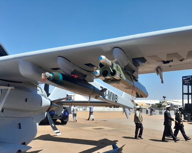
I was interested in the 70mm laser guided (mock-up) rockets on the wings - not sure if they are Thales or Roketson's - I suspect they are the Turkish Roketson's though..
The Cheetah R2Z story.
Project Bark
Part 1
Renier Keet was the Project Officer and gave a high-level explanation, in four parts, of the Cheetah Program. He made it sound easy, but believe me, he and his team at the program management level worked very hard to make it the success it was.
At the time, I was already living overseas. I joined Atlas in 1977 as junior Stressman and spent quite a lot of time being trained at Atlas.
I was also sent to Italy, home of the Impala, Bosbok and parts of the Kudu and to France, at Dassault, home of the Mirages. Due to my knowledge of aircraft structural design and analysis and the Mirage F1 AZ in-flight refuelling system, I was embedded in 1981 into the engineering team that worked on the prototype of the Boeing 707 In-Flight Refuelling and ELINT program.
When Rynier’s team arrived, my contract was extended, and I joined the engineering team on the Cheetah D2 & E. I had to keep a very low profile and spent quite a bit of time in a windowless basement office. Some days I was asked not to come to the office or not to leave the office since there were visitors from other places. My task was to learn as much as possible about the aerodynamics and airframe design of the Cheetah D/D2 and E. I could also contribute a lot of design knowledge from the 707 project to the design of the Cheetah in-flight refuelling system. I was not involved with any of the Electronics and Avionics of the Cheetah program. Derek Knoll from Atlas was responsible for that part.
After about a year I was asked if we would be able to do the Mirage III R2Z to Cheetah R2 conversion by ourselves in SA.
We had already converted a Mirage III RZ (#836) to R2Z in SA at the time. Brian Greyling was my team lead on that project. It was mainly to install an Atar 09K50 engine into a RZ airframe. That aircraft flew very successfully before any Cheetah did.
The contract negotiations started for the Mirage III R2Z to Cheetah R conversion. I soon learned that this was even more secret than the D2 and E program. The main reason for this was the very sophisticated cameras and sensors that the SAAF wanted installed. I was sent to the suppliers of these items and had to learn and understand the very tight installation specifications required.
I had to do a presentation to lots of SAAF Brass and Atlas big bosses. At age 33 and full of unjustified self-confidence, I convinced them that we could do this. Atlas was awarded the Cheetah R prototype contract, and I was appointed as project engineer. This could only have happened in those heady days where an inexperienced youngster could be given 18 months, a few million dollars and being told; “Build us a Hotrod Cheetah!”.
I had to assemble a 6-person specialist team from Atlas to join me for 3 to 4 months so that we could define the concept design and set the design interfaces with the Cheetah E. The Mirage III R/R2Zs are built around a Mirage III E airframe. The Avionics interface between the Cheetah E and the proposed Cheetah R was done by Derek Knoll, since he was also from Atlas already and part of the team on the ground.
This small team travelled to Ben Gurion and back every day in an unmarked old VW Kombi, which we had to park around a corner in an unmarked spot. Some of the guys were lucky to have their families there, but it was very difficult with them staying in a hotel and trying to be inconspicuous. We worked completely isolated in another windowless basement, but I had full access to the senior engineer on the Cheetah D/D2 and E, as well as most of the drawings and calculation data. We worked crazy hours and had some very funny incidents, which I tell in one of my books, ‘Top Secret’.
After 4 months we packed everything and moved back to SA and into the security isolated L-Hangar and started working on the detail design.
To be continued.
Photo 1
This was the Project Managment Plan presented to the SAAF and Armscor in June 1985. Atlas was awarded the contract.
Photo 2
The Cheetah R Prototype, #855, being moved to become the gate guard at Atlas Aircraft.
Photo 3
The two big projects being worked on at Atlas around about the same time. However, the secrecy surrounding a reconnaissance Cheetah kept it out of the limelight.
Photo 4
The engineering team that designed the Mirage III RZ to Mirage III R27. Some of these guys later joined me during the concept phase of the Cheetah R Prototype. Two of them also joined me in Russia when we worked on the concept design of the Mig-29 engine conversion project.
Photo 5
The technician team that did the Mirage III R conversion to Mirage IIIR27. Several of them also later worked on the Mirage III R27 to Cheetah R prototype build.
The Cheetah R2Z story.
Part 2
Due to the cameras and other sensors that had to be mounted in the nose of the aircraft, I had to concentrate on that part for both the aerodynamic and structural design before we could do detail work on the rest. Now I first need to explain something that seems to bother most people when they look at photos of the Cheetah.
The first comment is usually that; “It is a Kfir” or “the avionics makes the nose that long” etc.
There are 11 versions of the Kfir, which one are they referring to? The French built the Mirage III NG, which had canards. The Swiss put canards on their Mirage III RS. So, there was already a body of knowledge out there about canards on delta wing Mirages and derivatives.
Canards are added to delta wing aircraft to improve airflow over the inner part of the wing and to help with instantaneous turn rate. This gives an advantage to a fighter in the first part of a turn during a fight. Later in the turn, you need sustained turn rate, that is an engine function, more thrust helps you stay in the tight turn.
Another effect due to canards is that the extra lift provided by the canards and improved flow over the wings, causes the aerodynamic centre of pressure to move forward on the whole A/C. This makes the A/C more unstable and if it is not completely a modern fly-by-wire A/C, you need to move the CG of the whole A/C forward. As you use fuel, drop bombs or fire cannons, the CG shifts around and you must always ensure it does not move more than what the flight control and stability system can handle. These movements are plotted on centrogram charts for every possible mission and configuration.
The attached photo shows one such case. On the Cheetah this shift and new CAS (Control Augmentation System) and SAS (Stability Augmentation System) black boxes dictated for example that the 1300l droptanks needed to have a more fwd CG. New tanks were developed (1302 etc) so that you use the fuel from the back of the droptank. The problem then arises that if you get jumped and need to throw off half full tanks, the tanks will tumble and could hit the A/C, so the release mechanism and ERU settings on the pylons had to be changed and lots of testing done to make sure you get the tanks off cleanly.
The size (Effective Aerodynamic Area) of the canards are determined by the Specific Excess Power of the engine and the airframe structural limitations. The canards added to aircraft during the initial design phase can be as big as the engine power allows. Which means the structural frames they are attached to are designed for the aero loads. However, if the canards are a modification to an existing airframe, they can only be as big as the loads that the modified structural frames can carry. On the Mirage III conversion, Frames 13 and 15 had to be modified to carry the canard attachments. But since these frames are positioned during the initial build of the fuselage, they cannot be replaced and can only be modified. So, on the Cheetah D/D2 and E, the canards are only about 70% in area compared to the Mirage III NG or certain Kfir canards.
Once the canard sizes and aerodynamic profiles are established, you need to move the now heavier aircraft’s CG forward to comply with the Stability and Controllability requirements. That is where the longer nose comes in. The longer nose has shape limitations due the radar that is fitted in it and Frame 1, where the nose is attached to the fuselage. That can only be modified up to a certain point due to the loads going through the longerons on either side of the cockpit. So, the nose is designed to have a weight distribution, and aero loads generated by its shape, especially at high Mach numbers, that Frame 1 can carry. The nose shape also has a big influence on the airflow into the engine air intakes and over the cockpit. Photos of these various noses clearly shows little strakes and vortex generators to try and keep the airflow attached to the aft part of the nose and the fuselage shape further back. Nothing on a fighter aircraft is there without a purpose and, if possible, to serve more than one purpose at a time. When a design starts, each area is given a ‘Weight Menu’, to keep he design within balance. If a team needs to exceed their section’s ‘Weight Menu’, there are very serious meetings and trade-offs that take place. Think about that when someone makes a flippant comment about the ‘nose job’.
To be continued.
The Cheetah R2Z story.
Part 3
The SAAF Staff Requirement and thus the Technical Specification of the project had some very clear guidelines. The aircraft was intended to run very fast over enemy territory and had to be protected by advanced EW self-protection systems. It needed a greater range than the fighters and did not need to get into a fight. The navigation needed to be very precise, and the man-machine interface had to be similar to the Cheetah D/D2 & E but focussed on the camera and sensor operation in place of the weapons delivery. We also had to use as much common parts and systems of the other Cheetahs to reduce spares holding, specialist tools and additional ground crew and pilot training. There were a lot of detail stuff that took me many nights to study and create ideas how to achieve that.
Since the Mirage III R & R2 were based on a Mirage III E airframe, we used the full equipment list of a Cheetah E conversion as basis. The plan was also to keep the Cheetah R as ‘clean’ (low drag) and light as possible. The timeline given to us for the whole project was very tight, especially taking the complexity of the project and lack of experience in the team into consideration.
We kept the cockpit and instrument layout the same as the Cheetah E, except for the differences dictated by the Atar 09K50 engine vs the Atar 09C. The big difference in the cockpit was that Derek and his team changed the functions and software of the WDNS (Weapons Delivery and Navigation System) and the CSMS so that the navigation, target acquisition and weapons launch functions of the Cheetah E was reconfigured to do the camera functions and controls. There was also a ‘footprint’ video camera under the nose of the a/c so that the pilot could see the terrain below him in the HUD. We kept the installation design of the new ejection seat the same as the E, to avoid re-doing the clearance calculations and tests required for a new seat installation.
With the Aerodynamic Centre forward shift due to the canards, the Cheetah D/D2 and E could carry two 125 kg bombs below the canards via reinforcements done to the frames where the canards attach. I chose not to add these attachments since it saved weight and the R would not carry bombs. We removed the 30mm cannons and converted the large volume, normally occupied by the ammunition belts, into a fuel tank to extend the operational range. Since the cameras were very big and heavy, the weight saved between the ammo and fuel, helped that we could modify the surrounding structure up to frame 1 and new nose attachments, within allowable structural limits. I spent a lot of time monitoring the new nose & camera mass, since this was marginal. We did not have the wind tunnel capability in SA at the time and we did not have the original aero data of the Mirage III, so I had to use the Cheetah D/D2 nose data as basis for our calculations and design. My aim was to be able to keep the new nose of the R smaller and a little straighter that that of the Cheetah D/D2 since I wanted to keep the drag down. We did not have the same airflow over the single seat cockpit vs that of the two-seater, so we could change the nose angle a bit.
We wanted to keep the aircraft handling and external fuel tank carriage the same as that of the Cheetah E. During the Mirage III EZ to Cheetah E conversion, the original CAS (Control Augmentation System) and SAS (Stability Augmentation System) computers were replaced by units developed for the aero characteristics of the Cheetah E. We wanted the Cheetah R to handle just like Cheetah E. This was in line with the SAAF requirement that the pilot and maintenance crew conversion would be minimal. Since we had a different engine to that of the Cheetah E, we had to ensure that the fuel usage rate and sequence of use between different fuel tanks, did not move the aircraft balance outside of the flight control capabilities. This was for both usage during flight and in-flight refuelling, where the sequence of tanks filling was important.
To be continued.
The Cheetah R2Z story.
Part 4
I need to discuss the Cheetah D/D2 & E fuel system here so that the explanation on what we did on the Cheetah R makes sense. The modification of the Mirage III DZ/D2Z and EZ fuel system to cater for in-flight refuelling was quite complex. The existing fuel system on the Mirage IIIs consisted of a series of float valves situated inside the various integral fuel tanks. There were some differences between the Mirage III variants, due to their original design for specific roles. During the design of the in-flight refuelling for the Cheetah D/D2 and E fleet, we tried to make the system similar across the fleet, but it was not always possible.
Here is a high-level explanation of the fuel system modification: As the engine consumes fuel, the various float valves in the integral tanks throughout the aircraft open and close at specific fuel levels to ensure that the CG movement of the aircraft stay within the flight control limits. It must be noted that depending on the mission configuration, the fuel carried in both internal and external tanks can be up to 45% of the take-off mass. That is why fuel usage and CG shift control is very important.
There are also a whole series of possible scenarios that we had to cater for. Outboard tanks are used first, in case you get into a fight, you need to jettison the outboard tanks to be able to manoeuvre best, but you also needs to still have max fuel in the internal tanks to use afterburner and to get home. So, any time these external tanks are jettisoned, (or bombs dropped etc) the valves need to open and close in a way that ensures the CG is in an optimum position. Lastly, the fuel from the tanks are always fed to the engine via an Inverted Flight Accumulator. This is to ensure that the engine is always fed fuel while the aircraft could be in any attitude.
When the fighter is hooked up to the tanker aircraft, all the tanks needs to be open to atmosphere, since the pressure and rate of fuel (3.5 bar @ 680 to 900kg/min) flowing into the fighter will burst the tanks if there is back pressure. We had to add venting valves to all tanks, and they are automatically activated when the in-flight refuelling probe attaches to the tanker. The Inverted Flight Accumulator is then also isolated from the other tanks during refuelling because it must feed the engine while the refuelling is in progress. The float valves must open and close in a reverse sequence again to keep the CG within the flight control range. The filling sequence is also reversed, so that the internal tanks fill first and the droptanks last. The specific vent valves close when each tank is full. The system also needs to know what configuration the aircraft is in, ie what tanks or bombs etc is carried on which points on the aircraft.
For the Cheetah R, we had to modify the system in such a way that we could also incorporate the fuel tank in the cannon & ammo bay. The probe seen on photos is only the tip of the iceberg!
The Cheetah R was designed around two very sophisticated cameras. The first was a low altitude very high-speed camera. At altitudes of 50’ AGL and M=0.85, it could take photos with such high resolution that car licence plates were clearly legible.
The second camera was a high-altitude camera that records 90 degrees with the flight line, so you can fly parallel to the border and film 30 km beyond the border at around M=1. The navigation was so precisely planned that if you flew over the same route at the same time every day the guys who check the film later could see if someone has trampled grass or formed footpaths etc. You could also establish with that resolution what frequency the enemy's ground radar sites have if you photograph the antenna and analyze it later.
The lenses were so sensitive that the entire camera had to stay within +-2 degrees C for the entire mission. The shock wave over the windows in the nose through which the lenses aimed had to be designed in such a way that the air density change over the shock wave does not distort the photos. The film was 9" wide and there was a built-in computer that moved the film in the camera at exactly the ground speed opposite to the direction of flight so that the photos did not 'blur'. This meant that the cameras had to be linked to the WDNS and airspeed sensors.
The camera windows in the nose had to be polished camera lens quality glass. These windows were covered with disposable covers that would be jettisoned by a blast of compressed Nitrogen when the target area was approached. This was to protect them from being damaged by small stones & debris on the runway and to ensure the lenses are dust free during filming.
The shock and vibration limitations also made the installation very complex in such a small and insulated space.
To be continued.
This site uses cookies to help personalise content, tailor your experience and to keep you logged in if you register.
By continuing to use this site, you are consenting to our use of cookies.