USN Fleet Carrier Studies (Fall 1945)

Antonio

Moderator
Staff member
Senior Member
Joined
22 January 2006
Messages
3,885
Reaction score
1,133
A comprehensive source is Norman Friedman's "U.S. Aircraft Carriers".
"By 1945, the Essex class was considered unsuited to the new generation of naval aircraft. The 1945 fleet carrier was to have solved such problems in a hull suited to mass production". Also incorporating those learned from WWII experiences.

The Midway design started as an armored Essex. In pre-WWII thinking that was found an improvement. The addition of armour, demanded an increase in size in order to keep the same number of aircraft. At the end, Midway class was found oversized and less performant than Essex class for WWII needs.

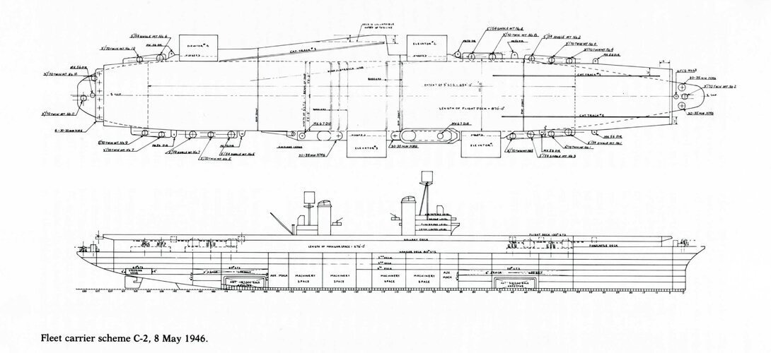
However, the basis for the Essex replacement was to start from the Midway design without armour. The definitive iteration was Scheme C-2, 8 May 1946. Once it was ready, that project and the parallel developed United States Class were cancelled in preference for a new combined design from both into what became the Forrestal Class.

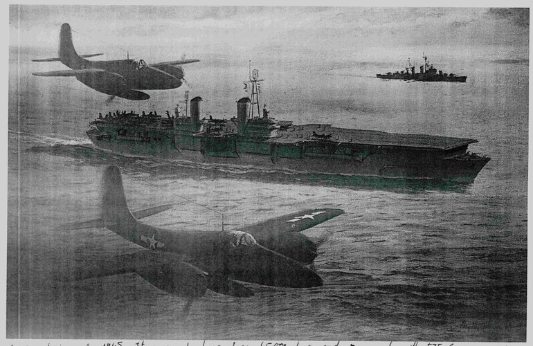
I have attached Friedman's book illustration.And a second attachment, an artistic rendering published in the back cover of Warship International Vol. 28, No. 3 1991. This is published by the International Naval Research Organization.


I scanned it from a photocopy made almost 30 years ago, that's why it looks awful.
 

Attachments

  • Fleet Carrier Scheme C 1946 Friedman.jpg
    Fleet Carrier Scheme C 1946 Friedman.jpg
    588.5 KB · Views: 452
  • Fleet Carrier Scheme C-2 1946 Warship Int.jpg
    Fleet Carrier Scheme C-2 1946 Warship Int.jpg
    707.6 KB · Views: 416
Wow this is super neat stuff.

Not a single deck elevator and the port catapult is similar to the United States layout.

What was the "30-35mm HMG"? An Oerlikon replacement I'm sure, but it's new to me.
 
Friedman provides more designs from 1945-46:
Schemes 1,3,4,5,6,8
Schemes A-1,2, B, B-1,2,3, C-1,2
Design CVB-X
Mostly quite similar proposals
 
It is worth to note the angled deck, even if only for the sporting catapult.

Not an angled deck, really, as that would imply that the recovery area would be angled. Very much reminiscent of the USS United States, which was an axial deck design with two angled waist catapults. This is basically the same but the island is sited where the flush-decked CVA-58 would substitute a fourth catapult.
 
What was the "30-35mm HMG"? An Oerlikon replacement I'm sure, but it's new to me.

Originally the Navy was looking at a 37mm free-swinging gun (possibly related to the M9 37mm gun deployed on a few PT boats. Interest swung back to something in the 30-35mm range but I think very little real work was done on this. So that was basically a placeholder for a "canon to be named later."
 
It is worth to note the angled deck, even if only for the sporting catapult.

Not an angled deck, really, as that would imply that the recovery area would be angled. Very much reminiscent of the USS United States, which was an axial deck design with two angled waist catapults. This is basically the same but the island is sited where the flush-decked CVA-58 would substitute a fourth catapult.

I'm aware of that.
I was wondering if such configuration did triggered something in Dennis Campbell's mind before he introduced the angle deck idea to real world during August 1951.
 
It is also interesting to note the use of two distinct islands, exactly like in modern CV Queen Elizabeth class or in the LHD Trieste.
Such ship appears to be ahead of its times in many respects.
 
It is also interesting to note the use of two distinct islands, exactly like in modern CV Queen Elizabeth class or in the LHD Trieste.
Such ship appears to be ahead of its times in many respects.
Queen Elizabeth and Trieste have two islands to provide uncompromised disposition of navigation and aircraft control facilities, while Malta had two not for an operational advantage but for a structural reason, an expansion joint was positioned between the island. I've read the expansion of very long decks on very large carriers started to be recognized as a serious technical problem by mid '40s and I think the reason of the twin islands on this design is the very same of the Malta's ones. Also a proof can be the clear outline of an expansion joint between the two islands in the drawing.
The need for expansion joints is also driven by where the strength deck is in the vessel. In US carriers and the Malta the strength deck was the hangar deck, so there was flex in the flight deck above that. In Ark Royal and the Armoured carriers the strength deck was the flight deck so no expansion joints were required.
 
Of course, it's not strictly necessary to have to split the bridge in two to accommodate an expansion joint. The Midway class had one forward of the bridge. At least I think it was forward of the bridge, I used it as a short cut while I was doing rounds as a volunteer at the Midway Museum and never looked up its exact position relative to the bridge.
 
Last edited:
I did a Shipbucket drawing for this a couple of months ago, so I'm just gonna post what I had on the forum over there (trimmed down of course). It should hopefully show the design evolution a bit more. All information comes from Friedman's US Carrier book.

"Three separate designs emerged, and none of them were completely satisfactory. Scheme A ended up being bigger than the Midways and encountered stability issues, so it was thrown away in favor of Scheme B. Scheme B-1 solved all the issues, but it ended up being too slow. Scheme B-1 evolved into B-2 and could achieve a top speed of 31.8 knots, but it did not meet the minimal armament requirements".

"It is important to note that Scheme A and B both used Essex's engine plants. So, it was instead proposed to take Scheme B and use something similar to the Midway's power plant to improve speed. The result was Scheme C-1, which had a top speed of 33.2 knots. But then the Board wanted it to carry more aviation fuel, so the ship had to be lengthened and carry additional armor. In April of 1946 Scheme C-1 became C-2. It carried more fuel and made up for all the shortcomings of the previous design, except for the part where it was too wide to transit the Panama Canal. The design featured 2 islands, an angled flight deck, and 4 side-mounted elevators. The 5” guns on the deck were moved down to sponsons on the hull, similar to what we see on the Midways. Requirements for small AA guns were removed and compensated with 16 x 3”/70’s, which were also mounted on sponsons. But at this point in time, the USS United States (CVA-58) had priority, and the two designs eventually merged into one".

Some specifications for the C-2 design:

Length Overall: 960’
Length at Waterline: 890’
Beam Overall: 160’
Beam at Waterline: 106’
Standard Displacement: 40,400 tons
Full Displacement: 54,500 tons
Speed: 33.1 knots

Aircraft: 53 total, 35 x F7F Tigercats, 18 x A2D Skysharks
4 x elevators
3 x catapults
4 x Screws (Speculative)

26 x 3”/70 AA guns, 13 x 2
8 x 5”/53 (Mark 16), 8 x 1
Note: It does not specify what 5” gun would be used, I personally feel the Mark 16 is the most likely.
An unspecified number of 30-35mm AA guns would also be carried. The design never emerged but was supposed to be an anti-kamikaze weapon, and the biggest mount a man can operate alone.

8 x SPG-56 GFCS
1 x Mk 64 GFCS

Hopefully, this gives more of a detailed perspective on the design. Lemme know if this wasn't helpful. Original info:
https://cdn.discordapp.com/attachments/750725522698534922/812447045863473182/unknown.png
https://cdn.discordapp.com/attachments/750725522698534922/812446617822298122/unknown.png
 
What an interesting air wing, seems like the USN were betting big on the Tigercat?
 

Similar threads

Back
Top Bottom