Plan target
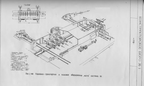
the design of the system-50
1. Appointment of -50
System-50, as one of the means of defense of Leningrad, intended for destruction (EC) anti-aircraft missiles, controlled by a ground station targeting, bombers with a reflective surface is not less than that of IL-28 fighter aircraft and cruise missiles (flying bombs ) with a reflective surface equivalent to the surface of the MiG-17 flying at altitudes ranging from 3 to 20 - 25 km at a speed of up to 1500 km / h, as well as individual bombers, fighter jets and cruise missiles (flying bombs), flying at a speed of up to 1800 - 2,000 km / h.
System-50 is based on the principle of all-round defense and executed by the type S-25.
P. Requirements for the composition and placement
means of -50
Due to the geographical features of the area placements of-50, the system should have a solid zone defense.
The belt 34 is formed defense missile systems (rocket-propelled anti-aircraft regiments) arranged in a circle on the removal of an average of 45 km from the city center.
Gulf area must overlap zones of fire fighting facilities, located on opposite sides of the bay and one of the complex, located on o.Kotlin.
.
Fire complex (anti-aircraft rocket regiment) consists of:
a) The station is aiming anti-aircraft guided missiles;
b) firing position in paragraph 200 missiles and missile control Warehouse 80 missiles;
For storage of military equipment, routine inspections of missiles and recharge them 34 firing positions in the system need to have 4 separate technical base and warehouse storage of missiles. Technical base and warehouse are located on the ring, equipped with missile systems (rocket-propelled anti-aircraft regiments).
Coordinates placement of four technical bases and separate warehouse storage of missiles number given in Annex 1 to this task.
Each technical base should be calculated on the contents of 120 missiles for each of its client firing positions. Separate storage must be designed for the maintenance of 400 missiles.
Note: the design of the technical bases provide for the possibility of equipment and testing missiles with a special charge.
For fire complex (shelf) № 35 o.Kotlin necessary to have storage facilities for 160 missiles. Emplacements complexes (regiments) № 33 and № 34 are not in the structure of warehouses for storage of missiles and 80 are provided by a separate warehouse.
All missile systems (anti-aircraft rocket regiments), the technical base and a separate storage system must be connected by roads with concrete pavement.
Provide early warning of fire systems (anti-aircraft rocket regiments) of enemy air raids and data traffic situation in-50 and KP Special Leningrad Army Air Defence System-50 should have a continuous circular zone of long-range reconnaissance, providing detection and identification of aircraft at altitudes of 3 to 25 km.
Zone 10 is formed long-range reconnaissance radar sites.
Among these 10 sites included three existing radar-range reconnaissance unit (№ № 7, 8, 9) System-25. These sites should be refitted and equipped with technical means in accordance with the requirements of the radar sites range reconnaissance system-50.
Radar units with long-range reconnaissance data system must provide notification of anti-aircraft rocket regiments of enemy air is not less than 6.5 minutes. to the entrance of aircraft in the area of detection stations missile guidance.
Note: For the regiments stationed west and north-west of the city of Leningrad, the warning time is provided to a height of 3 km at a target speed of up to 1500 km / h, and to a height of 5 km at a target speed of up to 1800 km / h.
-50 The system should include three radar site near intelligence.
Radar sites near intelligence should provide target designation anti-aircraft rocket regiment commander and commander of the battery (group) is not less than 2.5 minutes. at 3 km and not less than 3 min. at altitudes of more than 5 miles to the entrance of aircraft in the area of detection stations missile guidance.
Radar range reconnaissance units with equipment for communicating the air situation, should provide target information to commanders of anti-aircraft rocket regiments of not less than 5 minutes. to the entrance of aircraft in the area of detection stations missile guidance.
To manage the system and transfer target designation in the system - 50 shall be provided for the main command post system, territorially integrated with KP Special Leningrad Army Air Defence, emergency command center and an auxiliary control point system, geographically aligned with the radar sites near reconnaissance number 1 and number 2
Power to all system objects-50 should be carried out by high voltage power lines Lenenergo or district energy systems through down substations.
To ensure the power supply system facilities in case of a power failure on the network, each object must have an autonomous power.
For the production of medium repair of the main technological equipment in the system is necessary to provide 50-2 repair shops, geographically aligned with the technical bases of number 1 and number 4.
For the production of medium repair of mechanical, heat engineering, power and communications equipment in the system to provide special workshops -50 (base) and place them in a suburb of the city of Leningrad.
For the training of the system-50 shooting in the complex (anti-aircraft rocket regiments) № 13 should provide the necessary facilities (training center and school NCO).
Radio frequency range of the system components, 50 are established in accordance with Annex 3 to this number assignment.
All radio equipment system-50 should be able to work in conditions of active and passive jamming. Noise immunity of the individual system is provided by means of the measures specified in the requirements for these funds.
The system-50 must be provided no mutual influence of radio equipment system.
C. Requirements to System-50
System Management-50 should be administered with the main or alternate command centers.
System-50 on the organization and management of communication is divided into three sectors, each of which is divided into sub-sectors.
The structure of the first sector to be included 11 anti-aircraft rocket regiments (from number 1 to number 11), radar reconnaissance unit near number 1 and technical base number 1.
In the second part of the sector should be included 11 anti-aircraft rocket regiments (from number 12 to number 23), radar reconnaissance unit near number 2 and technical base number 2 and number 3.
The structure of the third sector should be included 12 anti-aircraft rocket regiments (from number 24 to number 35), radar reconnaissance unit near number three, number four technical base and a separate warehouse storage of missiles.
To control the system-50, data traffic situation, object interaction system is necessary to provide basic communication via cable or combined (cable and radio relay) lines.
The system should provide a warning signal transduction red alert on the main (emergency) command center of the system - 50 and command centers of anti-aircraft rocket regiments (fire complexes) located west and north-west of Leningrad, in no more than 30 seconds. since the detection of the target, and command centers of all other anti-aircraft rocket regiment (through the main command post system - 50) in a time of 1 min.
System and data management to ensure the transition from primary to emergency command center without losing control of parts.
The system - 50 provides auxiliary control room, from which must be managed in parts of the first sector (the question of the feasibility of building an auxiliary control point in the system - 50 is considered in the design process).
IV. Common tactical and technical requirements
to fire complex
1. Firing complex should provide:
a) the possibility of defeat (EC) bombers with a reflective surface not less than that of IL-28 fighter aircraft and cruise missiles (flying bombs) with a reflective surface equivalent to the surface of the MiG-17 flying at altitudes ranging from 3 to 20 - 25 km at a speed of 1500 km / hour, and the individual:
- Bombers flying at heights from 3 to 20 - 25 km at a speed of up to 1800 - 2000 km / h;
- Fighter aircraft and cruise missiles (flying bombs) with a reflective surface, the equivalent surface MiG-17 flying at altitudes from 5 to 20 - 25 km at a speed of up to 1800 - 2000 km / h.
Loss (knock down) aircraft and cruise missiles (flying bombs) with the parameters of motion is provided at course angles from 0 to 60 the bisector of the sector survey station missile guidance;
b) the simultaneous guidance of 20 missiles in an automatic accompaniment on 20 single targets or in manual tracking of 8 single (group) targets with the motion parameters specified in paragraph 1a of this section. Number of simultaneously engaged targets depending on the height of their flight is set during the design and testing of missile systems;
a) basically pointing mode with the operational reliability of complex equipment, the probability of hitting a straight line flying aircraft at a rate of one aircraft at a range of meeting 20 - 30 km (active area) 2 missiles at the corners of the course to 40 and 3 missiles at course angles greater than 40 , and a flow rate of 3 missile at ranges 30 - 35 km - 85 - 90%. Probability of hitting the flying bombs respectively with 2 and 3 missiles mounted on the calculation results of production flight tests with the aircraft target;
d) firing missiles one frequency band of sight in any sequence at a rate not less than 5 - 6 sec. and different frequency bands with an arbitrary rate;
d) the ability to work in a military enemy use of passive and active interference. Noise immunity fire complex should be provided the measures specified in the requirements for missile guidance station and anti-aircraft guided missile.
2. Firing complex should provide defeat the purpose, maneuvers. Reducing the likelihood of defeat maneuvering targets specified in the design and testing of fire complex. The check is performed at speeds and accelerations of real planes.
3. Firing the complex should have a 200 fire missiles in the first 30 - 45 minutes.
4. Funds set fire to allow for a continuous stay in standby mode for the time necessary to conduct semi-annual or annual maintenance work on the individual nodes and blocks the neighboring complex, and in all other cases in tech6enie 12 hours break in 12 hours. In some cases, a determination of the complex in the standby mode 24 hours. Time to transfer funds in the complex ready to fire from standby should not exceed 2 minutes.
5. Time to bring in the complex means of fire ready to fire at AC Lenenergo must not exceed 6 minutes.
6. Power Complex fire should be administered as a network of Lenenergo, and from battery power. Autonomous power should allow parallel operation of the network. On Time battery power until the nominal load (with prior heating oil and water) must not exceed 3 minutes. The life of the engine for at least 10,000 hours.
7. The power supply system should provide the tires switchboards 380 and 220 volt voltage fluctuations: the station for missile guidance and missile control points - less than 2%, and for all other consumers - not more than 5% and frequency change no more than 2%.
8. The transition from line power Lenenergo powered by battery power, during normal operation, should not lead to a break in a combat operation.
9. Autonomous power should be placed separately from the main process building fire complex.
10. Technological building fire complex (station missile guidance and bins) must be protected from the blast and shrapnel FAB-250 at a distance of 6 meters from the blast site. The antenna is lowered pavilion reduction in the degree of protection for technological reasons.
11. Fire complex structures must be masked from aerial surveillance and Met lightning protection.
V. Tactical and technical requirements
to station missile guidance
1. The station shall be composed of 20 channels of missile guidance t provide:
a) the possibility of simultaneous automatic tracking up to 20 targets simultaneously and targeting them to 20 missiles;
b) the ability to simultaneously support manual to 8 single or multiple targets simultaneously and guided them to 20 missiles;
c) tracking of bombers with a reflective surface of IL-28 fighter aircraft and cruise missiles (flying bombs) with a reflective surface MiG-17 flying in the direction of the station, from the slant range is not less than:
The height of the
km in the MIG-17 IL-28
along the bisector
sector review
station on the edge of the zone ( 27 from the bisector
sector survey stations) along the bisector
sector review
station on the edge of the zone ( 27 from the bisector
sector survey stations)
3 25 25 37 35
5 30 25 45 45
10 40 30 60 50
15 45 33 65 50
20 50 35 65 55
25 52 40 65 55
Note: 1. In manual mode, target tracking range of sustainable support should not be lower ranges of automatic support at the appropriate heights.
2. Range of capture and automatic tracking of aircraft specified in the table specified in the design and testing of the station.
d) the time of transfer channels in automatic and manual tracking 20 targets simultaneously within the detection zone and the station with motion parameters specified in paragraph 1a of Section IV of this assignment should not exceed 60 seconds. The capture of one target should not exceed 5 seconds.
2. At the station should be provided for the centralized management of prelaunch missiles and alarm about the number and status of missile launchers on the lifting devices firing position and 5kanalov station.
3. As part of the station shall be provided for the device to determine when to start.
4. Functional control over the work station equipment must begin at the 5th min. and ends at 10-min. since the start switch station.
5. At the station must be provided equipment identification, providing the work in the "Silicon-2" (in accordance with the Resolution of the Council of Ministers on 23 September 1954. № 2006-927 and Decree of the Council of Ministers of the USSR on June 9, 1954. № 6295rs), and allows identify aircraft that are in the whole area of the radio station.
6. The level of side lobes of the antenna should be minimized (sidelobe level is specified at the design stage).
7. As part of the station should be a dedicated simulator for the training of combat races couple, allowing to simulate a complex traffic situation in the presence of interference.
Note: the order and timing of the development of the simulator is set by a joint decision of the Ministry of Defence and the ministries, leading its development.
8. Station equipment must be capable of alerting at least 15 channels of state maintenance work (other than quarterly, semi-annual and annual) for a period not exceeding the time to bring the station to combat readiness of the "cold" state (6 min.).
9. At the station must be able to work on the transmitter antenna equivalents followed by a rapid transition to a combat operation. When working on the dummy must be provided at the station carrying all kinds (except for setting up and testing (except for setting up and testing of antenna-waveguide system) tuning and routine maintenance without the emission of high frequency energy.
Specifications of equivalent strength, and their effectiveness is determined at the stage of design and development of a prototype plant before installation and adjustment work on the system.
10. Apparatus station should provide a continuous operation for 12 hours. In some cases, a continuous work station for 24 hours.
Maintaining station in constant combat readiness should be provided full-time combat crew stations in the time required to carry out routine maintenance (except for quarterly, semi-annual and annual) not more than 2 - 3 hours in a day.
11. The station should be capable of combat operations in conditions of active and passive jamming. For this purpose, the station must be provided: the system moving target indication (MTI) in manual tracking, frequency hopping sighting targets (time hopping sighting targets defined at the design stage), aiming missiles at the plane jamming on a "trehtochki" and other technical measures to enhance immunity station. The introduction of the station equipment MTI for the automatic tracking is considered at the design stage based on the results of research (R & D-40) and the testing of models of equipment at the site in 1956.
12. In developing the guidance station should be taken to reduce the size of equipment and improve its operational reliability through the use of light finger series of new parts and standardized units of equipment.
13. In the stations should be provided to ruling out the possibility of penetration of the hardware and cable channels rodents.
VI. Tactical and technical requirements
to the anti-aircraft guided missile
1. The rocket must ensure lesion (EC) aircraft motion parameters specified in Section IV of this p.1a job.
2. The missile must be at an average speed of a range of 30 km and a height of 20 km at least 900 m / sec. Range of the active site of the rocket to a height of 10 km shall be not less than 30 km.
3. The rocket must have realized the overload that provides guidance on the "three-point" method to heights of at least 20 km (height limit specified in the design process).
4. The design of missile boats and equipment must withstand the maximum normal overload of 15 - 20 (to be specified in the design process).
5. Warhead with radio controlled fuses must ensure lesion (EC) bombers in the pointing accuracy to 75 m, as well as fighter aircraft MiG-17 in the pointing accuracy of 60 m and the average values of relative velocities and angles of the meeting. Allowed some deterioration in the effectiveness of fire at extreme (00 - 2000 m / sec) and the angles of the meeting (from 0 to 190 ), when it should be ensured that paragraph 1c of Section IV of this assignment.
6. Fuel and oxidizer for the propulsion system must be components in mass production. At the design stage to consider the application as a fuel of one of the products (for both stages).
7. Onboard equipment missiles should allow continuous operation for 30 minutes. followed by a break of more than 20 - 25 min.
The total life of the on-board equipment must be at least 50 hours.
8. The design of the rocket must be capable of changing frequency radio system within the target range for a maximum period of 5 min. without further reference check before firing.
9. Time to prepare the rocket for launch since its inclusion in the training should not exceed 2 minutes.
From time to feed the command "start" with missiles guidance station before departing with a rocket launcher should be no more than 4 seconds. with a spread of 0,5 sec.
10. The missile has no loss of combat skills to ensure long-term (at least 1 year) stay on the trigger firing position with the natural changes in ambient temperatures from - 40 to +50 C, the wind speed at the surface to 25 m / sec., In the presence of precipitation and dusty air.
At an ambient temperature of more than +40 C may be protected from direct rocket sunlight and then installing it on the starter for 1 hour before the start.
11. The design of the rocket should allow its transportation by road by road at a distance of up to 1000 km, and by rail over a distance of up to 5000 km and fit into size 0 number. Disposable transportation missile system within a distance of 200 km should not require checks.
Loading and unloading must be carried out with the use of basic equipment, standard commercially available.
12. Shelf life missiles in warehouses in nezapravlennom state must be at least 5 years, and in full combat gear (with the oxidant) in the firing position - at least 1 year. And it is allowed during routine inspections of replacement units due to failure of electronic devices and separate components, such as rubber and gauges maturity date in accordance with the guests.
13. The design of the rocket should provide the content of the air tanks at the firing position without pumping and venting range of the ambient temperature 23 C.
14. Carrying out routine inspections of onboard equipment rocket should be provided for a maximum period of 30 minutes. and verification of the propulsion system for leaks should take no more than 40 minutes., including the sealing of the missile body.
15. The design of the rocket to allow replacement of the units and individual units on maintenance bases in the army.
16. On-board equipment must missiles designed to operate between routine test conducted no more frequently than once every 6 months for missiles, stored in a preserved condition and not more than once every 3 months for the missiles that are stored in the state to reopen the technical bases and firing positions.
17. On-board radio equipment, radio controlled fuses radiovizirovaniya and equipment must be capable of operation in the presence of organized, both passive and active interference. Criteria specified noise immunity of equipment installed in its inception and are checked when developing and testing.
18. The rocket should not be discharged at start-up and the initial part of the flight components and assemblies that could defeat the equipment and personnel of the firing position.
19. When designing the rockets should be worked out the possibility of installing a military variant missiles radio telemetry equipment.
20. The design of the rocket must exclude the possibility of entering into rockets rodents.
VII. Tactical and technical requirements
to the firing position
1. The firing position should include:
a) not less than 40 up-and-starting devices and equipment, providing mechanized supply missiles to the lifting device. Next to each lift-starter placed the power and signal systems of mechanized equipment supply missiles to trigger emergency management and equipment up-and-starting devices. In addition, every up-and-starting device must be placed cupboard based sources of supply of missiles and relay units control system start-up;
b) 2 battery command posts (Hopper), which is placed on two identical sets of control and calibration launching apparatus. Each one is designed to handle and control at least 10 triggering devices belonging to one group of five channels missiles guidance station.
On the battery command posts should be possible to accommodate crews firing position in their free time.
In one of the bunkers placed battalion command post with equipment alarm about the number and status of missile launchers on the lifting devices firing position and the commands with manual anti-aircraft rocket regiment for training missiles and communications equipment necessary to operate the battle;
c) check point missiles (BPD), intended for routine maintenance, inspection and installation of local oscillators for missiles coming from the technical base;
g) was heated and diked storage facilities for 80 missiles (for firing positions of all the complexes, except number of firing positions complexes 33, 34 and 35).
Note: for the firing position of the complex number 35 warehouses for storage of missiles doubles. Emplacements complexes number 33 and number 34 does not have in its composition of warehouses for storage of missiles. To ensure missile firing positions complexes number number 33, 34 and missile 35, of which 240 are used for the complex number firing position 35 and 160 (at 80 missiles) complexes for firing position number 33 and number 34.
e) special vehicles covered parking with room for duty shift personnel and three heated boxes;
e) a network of roads to transport rockets triggering devices and removal of the liberated territory with semi-fire position.
The network of roads in the firing position should ensure the passage of vehicles and avoid oncoming traffic;
g) 20 shelters, each of which is designed to accommodate the combat crew serving up-and-starting devices belonging to the same channel station missile guidance.
2. The firing position must provide:
a) placement and storage in triggering devices for shelters to 200 missiles;
b) preparing missile launch, including refueling oxidant in no more than 6 minutes. with the announcement of combat anxiety;
c) a continuous shooting with a total of 200 missiles in the first 30 - 45 min.;
d) simultaneous and separate fueling all missiles oxidizer 200 for the first 4 minutes. red alert after the announcement;
e) the safety of the operating personnel during start-ups during combat operations.
3. Each battery command post should be equipped with two identical sets of equipment operational command of communication and hardwire connection with the division command post. Each of the two sets should provide a link:
a) with shelters and up-and-starting devices of appropriate technology;
b) the commander of the group station missile guidance;
c) with the battalion command post;
g) with the command post antiaircraft rocket regiment.
4. Power supply of the firing position should be used for fueling up to 200 missiles and firing at the same time prepare for the launch up to 80 missiles in conjunction with the filing, with the rise and setting the trigger 40 missiles.
5. On the territory of the firing position must be provided signs for the proper distribution (in accordance with spetsmarkirovkoy) coming to a point in the day and night time missile system and signal the start of combat operations in the firing position, operating when the missiles to prepare.
6. Jobs fighting crew in firing position must be provided camouflage lighting.
7. At the firing position must be provided to ruling out the possibility of penetration of the hardware and cable channels rodents.
Vr. Tactical and technical requirements
to the base of
1. Technical Base (TB) should consist of process facilities and processing facilities (special equipment) for:
a) the content in the mode of long-term storage of 120 missiles for each of its client firing positions (except for the firing position of the complex number 35), of which up to one third tested in control and test station;
b) storage of accessories and spare parts units (combat units of sealed batteries, squibs, etc. (all contained on a technical basis missiles;
c) re-activation and re-conservation missiles;
d) conducting routine inspections contained in the technical basis of rockets (with the replacement and adjustment, if necessary, individual blocks of on-board equipment;
e) fueling with compressed dry air missiles and components of fuel;
e) equipment missile warheads and fighting tubes;
g) the storage of fuel components in the quantity required for refueling of rockets stored on a technical basis, a separate stock and folds in firing positions;
h) discharging the fuel components, and the neutralizing means filling fuel tanks missiles subsequent conservation;
i) delivery of refilled, dressed and proven missile firing positions on relevant;
k) of the physical-chemical analysis of components of fuel, air and industrial oils;
l) the calibration standard test equipment for general purpose and equipment from the on-board equipment spare parts, which are on a technical basis.
2. Performance and technical basis for conducting inspections should be 4 rockets per hour, and for the filling, filling the air with fuel and oxidant and export of missiles to firing positions - 6 rockets per hour.
3. Power supply technical base should be from the network Lenenergo.
4. In the event of a power outage on the network to provide the technical basis for each autonomous power, the power of which is to ensure the smooth operation of the process flow, and the boiler room and power supply.
5. Voltage fluctuations on the tires switchboards 380 and 220 shall not exceed for the control and test station 2%, and for other customers 5%, and the change in frequency should be no more than 2%.
6. Technical base should have internal railroad connected to the nearest railway line, loading, unloading and transportation facilities necessary for the delivery of missiles firing positions serviced by it, as well as the internal road network, linking together all the facilities and technical base and, in turn, associated with the external road network at least two entrances.
7. Technical base should have storage facilities for long-term storage of missiles, consumables, spare processing and auxiliary equipment TB.
Note: The storage capacity for each of the technical base is determined by the number of served its firing position.
8. The design of storage facilities being built within and outside the base, must be simple and cheap.
9. Building technical facilities should be unprotected type except explosive, which are constructed in accordance with current regulations.
10. Autonomous power should be placed separately from the main building of technological base.
11. All the facilities and technical base should have individual or group means lightning protection, such as extinguishing agents in accordance with the purpose of each building and masked from the air and ground surveillance. In addition, construction and technical base should have a means of communication (including dispatching communication), fire and security alarms.
12. On a technical basis should be provided for the main electric lighting and cloaking area, all facilities and jobs.
13. On the basis of the technical steps shall be taken to exclude the possibility of penetration of the hardware and cable channels rodents.
IX. The performance requirements for the radar
Good point nodes and near-intelligence
1. Six long-range reconnaissance radar units should be composed of an early warning radar, target acquisition radars, missile systems (anti-aircraft rocket regiments) and autonomous altimeters. The remaining long-range reconnaissance radar units should be composed of an early warning radar altimeters and autonomous.
2. Radar sites near intelligence should be composed of radar target acquisition, missile systems (anti-aircraft missile regiments).
Note: the number and specific types of radar stations to be included in the composition of each of the radar site is decided on the stage of conceptual design.
2. Each radar unit near-and long-range reconnaissance, except radar, should be composed of:
- Technical position node, which includes tools for remote management and control of the operation of all radar stations;
- Item processing and data traffic situation, including the indicator apparatus and equipment removal and data transmission;
- Command post node that allows for the operational management of all funds node to monitor the accuracy of the transfer of air situation and surveillance of long-distance traffic situation;
- Means of communication;
- The means of energy supply;
- Equipment identification, providing work in the "Silicon-2" and allows to identify planes in the zone of detection stations;
- Imitation-training equipment, allowing to simulate single and multiple targets in terms of active interference.
3. Early warning radar stations must provide:
- Detection, identification and tracking of airplanes and flying bombs with the reflective surface of the MiG-17 and the rate of up to 2000 km / h at an altitude of 3 to 25 km with a range of 170 to 400 km, respectively;
- Determination of the range and bearing to a target in the area of up to 15 in elevation in a circular survey with a maximum error of not more than 3000m and 5, respectively;
- Obtaining data rate to 4 and 6 times per minute.
Note: the question of the possibility of overlap of the zone with a single station and the need for more specialized stations within some range reconnaissance units is decided on the stage of conceptual design.
4. Radar target acquisition at work one station must provide:
- Detection, identification and tracking of airplanes and flying bombs with the reflective surface of the MiG-17 and the rate of up to 2000 km / h at an altitude of 3 km with a range of 160 km, at an altitude of 5 km with a range of 190 km and at an altitude of 25 km with a range of 200 km;
- Determination of the range and bearing to a target in the area of + 0,5 to 30 + in elevation in a circular survey with the maximum error does not exceed 500 m 0,5 and 80%, respectively, of measurements;
- The resolution in range and azimuth 1000m 1 - 2 ;
- Definition of the target height in the area of 1 + to +30 in elevation in a circular survey at ranges ravnyh90% detection range with a maximum error of no more than 500 and 80% of the measurements;
- Receiving rate data for 5 and 10 times per minute;
- Beginning from standby mode after 2 minutes.
5. Standalone altimeters must provide:
- Determination of the height of aircraft with a reflective surface of the MiG-17 and a speed of up to 2000 km / h at heights of 5 to 25 km with a range of 140 to 150 - 170 km, respectively, accompanied by manual;
- The maximum error of the height that does not exceed 300 - 500 m;
- The resolution in elevation 2 ;
- A review of the space in elevation from + 1 to + 30 .
6. All radar sites near and long-range reconnaissance should provide data on the main air situation, emergency command centers of the system - 50 and the auxiliary control unit for warning and control parts of the system, and radar sites near exploration sites and radar-range reconnaissance - in anti-aircraft missile regiments of the system - 50 for target acquisition to commanders of regiments (air situation data transmitted from said radar sites near and long-range reconnaissance) and the battery commander (air situation data transmitted from radar sites near intelligence).
On the long-range reconnaissance radar sites must be provided at the request of the National Air Defense Command Energy and space for equipment removal and data for the guidance of air defense fighter aircraft.
7. Issuance of radar data nodes air conditions must be continuous, with no time limit, and ensured the presence of active and passive noise, interference from weather factors and local items. Furthermore, it must be ensured simultaneous operation of all stations and radar unit without interference. The question of the extent and methods of protection against all types of interference is decided at the stage of conceptual design.
8. At the stage of conceptual design studies a question about the possibility of working on a unified plan position indicator.
9. Radar stations that make up the nodes must have the equivalent load to ensure that the station holding all kinds of tuning and maintenance work, except for work on waveguides and antenna systems, without the emission of high frequency energy. Specifications of equivalent load and the efficiency of design and testing of prototype radar prior to the installation and adjustment work on the system.
10.Elektropitanie radar unit must be carried out both on the network and on the battery power. Autonomous power should allow parallel operation of the network and placed separately from the main process buildings of the facility. On Time battery power until the nominal load (with prior heating oil and water) must not exceed 3 minutes. The life of the engine for at least 10,000 hours.
Note: on the radar sites near intelligence number 1 and number 2 power consumption is determined by taking into account the electricity supply emergency command post or auxiliary control point system.
11. The basic technological building site must be protected from the blast and shrapnel FAB-250 at a distance of 6 meters from the blast site.
12. Site facilities should be camouflaged from the air and ground surveillance and have lightning protection.
13. On the radar nodes steps shall be taken to exclude the possibility of penetration of the hardware and cable channels rodents.
H. tactical and technical requirements
a data transmission system
1. The data transmission system should provide:
- Automatic removal and transfer by delayed TV on underground telephone cables or combined (cable-radiolineynym) lines on the main, emergency command post systems - 50, the auxiliary control room and face images of anti-aircraft rocket regiments plan air situation with radar screens three short-range reconnaissance units and six sites of long-range reconnaissance,
Note: in the design process worked out the feasibility of replacing the method of delayed television transmission plan of the air situation from radar screens long-range reconnaissance units by automatic or semi-automatic removal of target coordinates.
Each of the three radar sites near intelligence must also transfer to the CP anti-aircraft rocket regiments of the sector are two separate programs for independent channels (one program for each regiment). In case of failure of one of the neighbor nodes should be provided by the simultaneous transmission plan air situation with the two existing units at the command of all anti-aircraft rocket regiments of six different programs (one program for each regiment).
Plans air situation with a 6-radar-range reconnaissance units must be passed to the command of reactive anti-aircraft regiments, which are in the sectors of action of these nodes, as the main and emergency command post system - 50 and the auxiliary control room. Connection diagrams auxiliary control room and face antiaircraft rocket regiments to the appropriate nodes is determined by long-range reconnaissance in the design process.
Along with a picture of the air situation plan transmitted from these radar sites near-and long-range reconnaissance, must be sent additional information about the goals (the number, height, characteristics of the target).
Teams targeting (in the form of arbitrary labels and signs) must be passed to the command of anti-aircraft rocket regiments from the primary, alternate command centers of the system-50 and the auxiliary control room. with plans to use the air situation picture transmitted from the radar site near intelligence;
b) automatic and semi-automatic volume target coordinates with all indicators radar sites near and long-range reconnaissance and transfer to the primary, alternate command centers of the system - 50 and the auxiliary control room. The summation of these coordinates and the map on the screen (80 cm in diameter, with coverage area radius of 800 km. Screen sizes are specified at the stage of conceptual design) of the primary, alternate command centers of the system - 50 and the auxiliary control room with the number, height, number and nature of the targets.
The equipment must allow for noise filtering and to make changes and updates to the traffic situation. Receiving screens (tablets) transmission system must provide peresem traffic situation on the big screen commands to the system or have for that special outputs for automatic data transfer to the big screen.
The time taken to pass data from the detection purposes until the display on receiver screens (tablets) intelligence group to be limited to 30 seconds.
The marks on the purpose of the screen should be reproduced with an accuracy of 1% of the diameter of the screen.
Each set of transmission equipment together with the linear transmission path should provide at least 90 notches Target for 1 minute.
2. Data transmission equipment to provide air situation (with reserve) a continuous round the clock operation.
XI. The performance requirements for the main
and emergency command post system - 50
1. The main command post system is designed to control the means of 50-and geographically aligned with CP Special Leningrad Army Air Defence.
On the main (alternate) command post system should be provided for placement of communication and processing equipment, providing the commander and his staff to obtain data traffic situation on the means of-50 from the command post of the Special Leningrad Air Defense Army, the transfer of commands and instructions, obtaining an order from a superior command, as well as obtain information about the status of funds-50 and combat activities of subordinate troops to take the necessary decisions.
2. A crew of conceptual (alternate command post system should be composed of three operational and one reconnaissance group to ensure that the work on the ground (the spare) should be provided for manual placement of special technological communication equipment and accessories.
3. Operational and intelligence groups should be placed in specially equipped premises, consisting of operational and intelligence halls and classrooms for officers fighting crew.
4. These air situation should come to the main (emergency) command center of the system of all radar sites near-and long-range reconnaissance system-50, three radar units range reconnaissance (№ № 7, 8 and 9) of the DG-25 and CID Special Leningrad Army Air Defence. Data transfer of funds from the system to the primary (emergency) KP should be made by the means specified in Section X of this task and on the phone, and from the GT RTV - on the phone.
On the main (alternate) command center of the system must be placed equipment providing for manual processing of incoming data traffic situation and playing it on the big screen commander, established in operative room. The screen size should be 4h6m and have a resolution of at least 8 km. Processed (in some cases, raw) data traffic situation must be passed to the command of anti-aircraft rocket regiments of-50 for telephone lines.
5. At the design stage is to be considered the possibility of signaling devices for display workplaces intelligence officers of the characteristics of the main goals on the scoreboard, alternate command centers and auxiliary control station and signal devices for the display of all the PS anti-aircraft rocket regiments on the scoreboard primary and backup command posts state funds and combat activities -50 parts of the system and the presence of missiles in firing positions.
6. On the main (alternate) command post in specially equipped premises shall be provided accommodation communications equipment, as well as special equipment to play the overall traffic situation on the screen in the operational room. In addition, there shall be placed under the spare parts warehouse and workshop minor repairs to equipment base (reserve) KP system.
7. Power supply of the core command post system should be carried out both on the network and on the battery power. Autonomous power should allow parallel operation of the network and placed separately from the main unit. On Time battery power until the nominal load (with prior heating oil and water) must not exceed 3 minutes. The life of the engine for at least 10,000 hours.
8. The power supply system of the main (Spare) KP system must ensure that the tires of distribution boards 380 and 220 volt voltage fluctuations at a 5% and frequency change no more than 2%.
9. The main gearbox system must be protected from direct exposure to the FAB-10000 and provide two protected the entrance to the underground room.
All accessories (power supply, ventilation, heating, chemical protection and the protection of military radioactive substances) should allow for a continuous work of 150 men (the system - 50) for 72 hours in a pressurized environment of the main gearbox system.
10. Above the main gearbox system should be provided for the construction of ground space to accommodate staff of the system - 50 and holiday destinations of the number of personnel on duty shift fighting crew of the main gearbox system. You must also provide for the construction in the immediate vicinity of the main barracks and KP living space for members of the Communist Party and the main headquarters of the system - 50.
11. Emergency manual system must be protected from direct exposure to the FAB-1000 (to be confirmed at the design stage) and to provide protection against chemical and radioactive substances fighting (according to accepted norms). In addition, the emergency control shall be masked from the air and ground surveillance.
12. On the main (alternate) command post system - 50 steps shall be taken to exclude the possibility of entering into the apparatus of rodents.
HP. The performance requirements for auxiliary
control point system - 50 (CPG)
1. The auxiliary control unit (VPU) intended to control anti-aircraft rocket regiments, technical base and radar unit near intelligence, which is part of the first sector. CPG should provide data traffic situation, data on the state of resources and combat the activities of subordinate troops needed for a decision.
2. The auxiliary control unit must be aligned geographically with the building of the radar data processing site near exploration and allow for the installation of operational and intelligence groups, to ensure the works are to be provided for special technological equipment and communication devices.
3. Operational and intelligence groups should be placed on the SPM in specially equipped premises, consisting of operational and intelligence halls and rooms for officers fighting crew CPG. In addition, the CPG should be provided facilities for the personnel of the rest of the number of combat duty shift calculation CPG.
4. Operating room CPG is designed to accommodate the task force.
Operationally room must be provided jobs commander and officers napravlentsev (by anti-aircraft rocket regiments and technical base). Each job should be equipped to handle operational command (telephone hubs and devices.)
At the design stage should be considered the possibility of using warning devices for display on the display characteristics of the CPG purposes (employment officers Intelligence Unit TLU) and state funds and combat activities of subordinate units, the presence of missiles in firing positions (with CA anti-aircraft rocket regiments).
5. Air situation data to be transmitted to the RCD with a radar site near reconnaissance number 1 and long-range reconnaissance radar sites that provide data KP antiaircraft rocket regiments of the first sector with the means set forth in Section X of this assignment, as well as telephone lines from the primary (Spare) command point system - 50.
These air situation should come to the officers of the intelligence to adjust the overall air situation displayed on the screen in operative room. Total air situation displayed on the screen using special equipment.
6. Power tools CPG should be relevant to the radar site near intelligence.
7. CPG should be protected from direct exposure to the FAB-500 (to be confirmed at the design stage), from the effects of chemical and radioactive substances fighting (according to accepted norms), masked from the air and ground surveillance.
8 At the CPG steps shall be taken to exclude the possibility of entering into the apparatus of rodents.
HS. The performance requirements for facilities
communication system -50
1. Means of communication systems-50 are designed for system control and data traffic situation and the need to provide reliable and continuous communication:
a) between the primary (spare) CP-50 system, NBI-25 system and the Staff of Air Defense Forces over the telephone and telegraph channels - cable and is backed up by radio waves which;
b) between the (spare) CP-50 system and the CP Special Leningrad Army Air Defense by telephone channels - by cable;
c) between the primary (spare) CP system, each radar unit near exploration and CPG by telephone and telegraph communication channels - by cable. In addition, the cables are provided channels for data transmission methods delayed television;
g) between the primary (spare) KP system and each anti-aircraft rocket regiments by telephone channels - by cable;
d) between the primary (spare) KP system and each radar range reconnaissance unit (including three long-range reconnaissance radar unit system -25) over telephone and telegraph channels - via cable or combined lines - by cable and microwave links.
Telegraph and telephone communications between the main (spare) KP system and each radar range reconnaissance unit must be backed up communication channels on the radio on short wave, which is necessary to provide the receiving and transmitting radio centers;
e) between the radar-range reconnaissance units, the main (spare) enterprise systems, CPG and CP anti-aircraft rocket regiments on the same channel to transmit data delayed by television. Wiring Diagram and TLU CP anti-aircraft rocket regiments to the appropriate nodes is determined by long-range reconnaissance in the design process;
g) between the base (spare) CP system, TB and CPG by telephone channels - by cable;
h) between each radar unit near KP exploration and anti-aircraft rocket regiments the sector by telephone channels - via cable. Provision is also two circular channel data delayed television methods, these channels each other mutually reserve;
s) between MP each antiaircraft rocket regiment and its serving TB telephone channels - by cable;
a) each anti-aircraft rocket regiment has a connection channels with neighboring shelves - by cable;
l) for each TB should be provided Dispatch process control, with access to the control of TB;
m) In addition, there shall be: the connecting link on the main straight cable (spare) KP system - 50 from the CO, the central telegraph and long-distance telephone station of the Ministry of communication with ATC City Council, with the station, "rf" communication with a communication Leningrad BO and the Navy.
2. Establishment of communication in the system-50 should include the following types of communication:
- Communication Command;
- Communication alert;
- Liaison;
- Link rear (including the dispatch communication system objects - 50 priobektami high-voltage substations 85/10 - 6 square system, and radio nodes near and long-range reconnaissance - with supporting high-voltage substations of 110/35 kV).
In addition, at each site of the system should be organized:
- Indoor team communication;
- The connection object to the residential campus;
- Internal communication and radio each town;
- The alarm object.
3. Provide communication of anti-aircraft rocket regiments, TB VUSov, radar sites near and far from the nearest survey of district and provincial units of the Ministry of Communications and communication nodes with other departments on a telephone circuit.
4. If the damage is one of the sections of cable or failure of one anti-aircraft rocket regiment in the sector of the main channels of communication that are appropriate to the current anti-aircraft rocket regiments, shall not be violated. To do this, cables, other than the existing channels, bypass channels provided links.
With the simultaneous failure of two cable sections in the sector (at least one radial) provide the ability to restore the basic relations of the remaining objects with the commutation.
The system - 50 to provide for the establishment of auxiliary communication nodes (MAS) protected from the blast and shrapnel FAB-250 at a distance of 6 meters from the explosion site (specified at the design stage).
5. At all sites provide the necessary switching, amplification and translational apparatus.
6. When designing the lines for long-range reconnaissance radar sites must be taken into account the needs of the Ministry of Communications on the assumption that these lines will be served by this Ministry.
7. Trails cable lines should be chosen close to existing roads and agreed with stakeholders.
In wetlands provide cabling along roadsides.
XIV. Tactical and technical requirements
a power supply system
1. Objects in the system - 50 must be provided with power from on-site high-voltage substations (35/10 - 6 m), connected to each other in the ring are supplied by the controversial high-voltage substations (110/35 kV).
2. In addition to supply of power systems, each object (except for special workshops located in the suburbs of Leningrad) must have an autonomous power, allowing the parallel operation of the network.
3. The transition from the electrical power system on the parallel autonomous power and back shall be carried out without interruption in combat work.
4. Equipment and facilities of the system power supply facilities shall be designed to work around the clock.
5. power supply system should provide the tires on-site substations (35/10 - 6 kV) voltage variation over 2%.
6. Design of transmission lines, power transformers, and the number of cells for the exhaust from the substation feeders on the side 35 and 10 - 6 m should be based on the connectivity of regional stress in size in agreement with the energy provider.
7. On the long-range reconnaissance radar sites must be provided independent sources of power supply means.
8. Objects of the system should be equipped with surge protection.
9. Dispatch communication device power system supplying the on-site substation 35/1- - 6 square system - 50, should have an autonomous system of communication.
10. Trails cable lines should be chosen close to existing roads, and in wetlands - along roadsides or special flooring.
XV. Basic requirements for spare parts warehouses
bodies and repair of the system -50
A. Requirements for spare parts warehouses facilities
1. In all areas of the system-50 should provide spare parts warehouses for the storage of the required number of spare parts, components, assemblies and auxiliary technological equipment available at the facility, as well as operational and consumables.
2. In-stock spare parts shall be provided by the nature of the stored shelves technical equipment. For storage of chemicals and lubricants should be provided special storage.
3. The warehouse spare parts should be located close to the main process building object. Placement of spare parts warehouse in the firing position to provide in room check point missiles.
4. Storage facilities, for cold storage (for varnishes, paints and lubricants) should be warm, the temperature and the relative humidity inside the room must provide storage for spare parts. The heating system of warehouses selected based on the received for this object.
5. The amount of stored stocks of spares must provide 3-month operation of the equipment.
B. Requirements for Repair Shops objects
Repair shops facilities should be located in the same building with the warehouses of spare parts. At the reins of radar near and long-range reconnaissance, missile guidance stations, technical databases, primary and alternate CP provides for a single workshop with two compartments: one compartment for small repairs radio, electrical parts and communications equipment, and the second - the mechanical department for minor repairs and special process auxiliaries.
In the mechanical department of the repair shop and technical base should be made of the equipment has been installed and the type of building number 23 TB-5, E, 11-25 system to include equipment for minor repairs are motor and trailers.
B. Requirements to storage base ZIPov
1. Warehouses base ZIPov (2 in the system-50) must be located geographically at maintenance bases and have storage areas that provide storage of all basic sets of spare parts (stations missile guidance, radar stations, nodes, data communications equipment, communications equipment, start-up and fueling equipment, electrical equipment , test equipment, support equipment, cable management and operating materials).
2. The volume range of spares stored property base and the needs of the area should be determined by the design organization based on initial data organizations developing manufacturing equipment.
3. Storage areas must meet the basic spares requirements arising from the nature of the property stored in them.
G. Requirements for the repair bases
1. Repair base (2 in the system-50) for the average repair main equipment together with warehouses storing basic spares to geographically co-located with the TB-1 and TB-4 (not included in the process flow of these TB) and have the access roads and railway lines .
2. Each repair station must have its composition:
- Shop for repair of technological equipment of the stations missile guidance, radar stations and nodes data transmission equipment;
- Repair shop missiles and components of their units and blocks;
- A central laboratory for calibration of measuring equipment;
- Repair shop equipment.
Note: The design of the equipment is made by the original data organizations developing manufacturing equipment.
3. As part of the central laboratory for calibration of measuring equipment and plants for the repair of technological equipment of the stations missile guidance, radar stations, nodes and data communications equipment, repair instruments should be provided for the following mobile repair workshops and laboratories:
- Electrical engineering laboratories and workshops (4 - 6 pieces. System - 50);
- Small general station for verification and minor repair of high-frequency measuring equipment (4 sets in the -50);
- Small general-station test equipment for KIS (4 sets in the system - 50);
- Test and repair shops type KRAS (8 sets in the system - 50);
- Special buses to transport units and refurbished test equipment (8 buses in the system -50).
4. The temperature and humidity inside the production areas must meet the requirements of the same type of facilities. Buildings should be equipped with central heating, running water, ventilation and sanitation. In the radio shops and repair shops devices floors should be covered with parquet or linoleum carving.
5. The buildings must be equipped with fire and security alarm system.
6. For the production of medium repair of mechanical, heat engineering, power and communications equipment to provide special workshops (base) in a suburb of the city of Leningrad.
XVI. The main technical requirements for buildings and facilities
on technical grounds, residential and administrative and economic
buildings, facilities protection and masking objects in the system-50
1. The deployment system objects-50 is set in accordance with the application number 1 and number 2 to this task.
2. local design development on the areas of the system-50 must meet the requirements of the "Provisional instructions for drawing up master plans of military camps of the Ministry of Defence" (1954).
3. Objects radar sites near (including PCP and SPM system) and long-range reconnaissance and anti-aircraft rocket regiments should consist of technical buildings and structures (technical area), as well as building barracks, administrative, economic and drill teams and officers of the houses (residential township) placed in close proximity to the technical area. The residential campus building barracks, administrative and economic combatant groups (service area) should be separated from the houses of the officers a green area.
4. Technical base of -50 should consist of:
- The technical area (buildings and structures of the process stream and storage facilities for missiles);
- Service areas (administrative buildings, covered parking and garages for tractors and motor vehicles, autonomous power, boiler, pump and compressor stations, chemical laboratory, fire station and rail car building for duty shift drivers);
- Residential campus (barracks, dormitories, houses of officers and the building of an economic group).
The technical area and service area must be contiguous. Residential town must be placed separately and in the immediate vicinity of the base of the other zones.
Note: In the process of designing residential campus should consider the option of placing the barracks and buildings of the economic group separate from the house officers. At the same time, the barracks must be isolated from the homes of officers.
5. Each repair facility with a warehouse base spares should have its own technical area adjacent to the technical area related technical base. Buildings and home service area officers repair facilities should be located in a residential town, combined with a residential campus base.
6. Master plans of objects (including residential campuses) system-50 does not have to be typical, the layout of each site (zones) should be individualized and take into account local conditions.
7. When the location of reactive anti-aircraft regiment and technical base at a distance from one another 3km cantonments of these objects can be combined.
8. All the main building TB and residential buildings should be of stone or cinder.
9. Buildings of residential townships of -50, technical and repair bases and the main gearbox system shall be provided with central heating, water supply, sanitation (industrial and economic) power supply, communication and radio (only residential townships).
10. In technological buildings radar sites near and far intelligence, GSB, SPM systems and anti-aircraft rocket regiments should be provided for heating, water supply, ventilation, power supply, communication and alarm system. In addition, the RFP and provide CPG and sewers.
11. designing spaces and residential barracks funds and domestic premises should be made on the basis of the indicative staffing levels of personnel. In the design to provide the possibility of expanding the areas of 25%.
12. With the development of master plans and decisions of external networks of water supply, sewerage, heat supply, power supply and communication must take into account the possibility of future development in the amount of 25%.
13. For the calculation of the living space in the homes of officers, as well as dormitories, military barracks, headquarters, canteens, clinics, clubs, garages and other accessory buildings to adopt regulations of the Ministry of Defence.
14. Means of masking objects in the system should have a purpose - to hide objects from visual ground (on the side of roads, settlements, etc.) and air surveillance.
The primary method of masking objects from ground surveillance appropriate to use natural remedies masking (topography and existing forests and planting of trees and shrubs). In some cases, it is fashionable to allow the use of special protections and camouflaged buildings. in doing so, provide for the possibility of maximum coupling of existing forests.
Masking activities should be carried out during construction and incorporated into projects of individual objects and structures.
15. All building systems objects-50 must be provided with fire.
16. All areas of system objects, except for residential townships must have a special territory guarding and security structures.
Measures to protect the system objects are defined-50 design organization, and agreed with the Ministry of Defence.
On the long-range reconnaissance radar sites in the vicinity of hotels, necessary to provide enhanced security.
HVP. The main technical requirements for construction
trunk and feeder roads
system objects-50
1. Technical class for all roads - Sh
2. The width of the land of cloth:
- For trunk roads in virgin areas - 10m;
- For trunk roads using existing roads with stone coating provides existing web width, but not less than 9 m;
- For external access roads to the firing positions and technical bases on virgin lands - 9.5 m, and the use of existing roads with stone covering the current width, but not less than 9 m;
- For external entrances to residential towns and stations missile guidance - 7.5 m
3. The width of the carriageway:
- On the main roads and outside entrances to the firing positions and technical bases - 7.0 m;
- At the entrances to residential towns and stations missile guidance - 4.5 m;
- The exit of the main ring road to the objects of anti-aircraft rocket regiments should be capable of turning the train with rockets to move in the opposite direction.
4. Type of coverage in the virgin areas for all roads - cement concrete, and the use of existing roads with stone surface - asphalt concrete.
5. width of the ROW:
- For trunk roads - 45 km;
- For access roads to the sites - 30m.
6. Artificial structures constant type:
- Large bridges - metal and concrete, and medium and small - reinforced concrete;
- Tubes - reinforced concrete;
- Dimensions of bridges - G-7.
7. Maximum longitudinal gradient of roads and entrances -6%.
8. The smallest radius of the roads in the plan - 100m.
9. The smallest radius of the road in terms of the ramp at the junction with the main roads and outside entrances - 30m.
10. The smallest radius of vertical curves:
- Concave - 600m;
- Convex - 2000m.
11. The design speed - 50 km / h.
12. The intersections of roads with railroads to provide in the same level with the equipment crossings with gates.
Note: Mga and the Ulyanovsk region to provide a railroad overpass.
13. When passing through the wetlands in the project roads be possible laying of cable lines in the roadside embankment.
14. The main internal roads in the technical Hone radar sites, anti-aircraft rocket regiments, technical and repair facilities to provide cement-concrete, and residential campuses - with gravel and tarmac, besides the main entrance roads that run-cement concrete.
Note: at the design stage should be considered are the use of asphalt concrete pavement for all roads in residential townships.
15. The width of the rides for the construction of internal roads and access roads to provide within the dimensions of the land fabric and ditches without reserves.
16. In the area of Petrokrepost build a bridge across the river. Neva River with access to his ring backbone of the road.
17. Create a ferry to transport rockets from a separate warehouse on the island of Kotlin.
18. Build a radial highway Pavlovsky Petrokrepost black finish width of 6 meters.