- Joined
- 6 August 2007
- Messages
- 4,374
- Reaction score
- 9,170
The claim has been made in several threads that "Organization X" can develop and validate a Very Low Observable aircraft using only a compact near-field RCS range — no far-field range, no far-field validation. Measurement physics has opinions about this.
Strong opinions.
Let's examine them together!
Far Field vs. Near Field: The Core Distinction
Operational radars illuminate targets from distances vastly exceeding the target's own dimensions. At those distances the incident wavefront is planar to any reasonable engineering approximation. That planar-wave condition is what produces the RCS number that matters — the one a threat system actually sees.
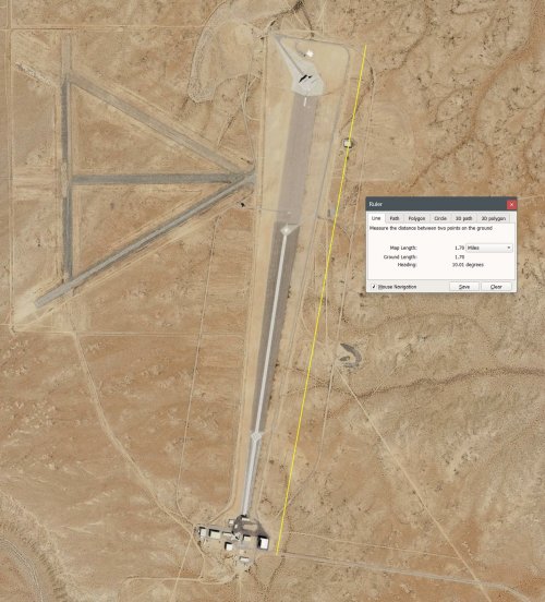
The far-field boundary is defined by R = 2D²/λ. For a full-scale combat aircraft at frequencies of interest, that distance is measured in kilometers. A far-field range measures RCS under conditions that directly replicate operational geometry. No transformation required. No assumptions about measurement validity. The number you measure is the number that matters.
Near-field measurements are made well inside that boundary. Incident wavefronts at the target are curved. Scattering under curved-wave illumination is physically different from scattering under plane-wave illumination. Testing indoors eliminates weather, EMI, and OPSEC exposure. It does not eliminate the fact that you are no longer measuring the quantity you need.
NF/FF Transformation: What It Does and What It Cannot Do
Near-Field to Far-Field transformation recovers the far-field scattering pattern from near-field measurements via a spatial Fourier relationship. The mathematics are exact in theory. In practice, three problems dominate.
That third point is where facilities without far-field access fail. Validating a NF/FF transformation requires comparing its output against an independent far-field measurement of the same target. Without that reference, you can verify internal consistency. You cannot verify accuracy. Those are not the same thing.
Why Far Field Is the Source of Truth
Far-field measurement directly replicates operational electromagnetic conditions. Plane wave in, scattered field out. No reconstruction, no assumed geometry, no transformation error budget. The measured quantity is the operationally relevant quantity.
Near-field measurement is an inference. For targets with conventionally large RCS the inference is close enough to be useful. For targets at the low-observable extreme, the gap between a direct measurement and a well-executed inference becomes operationally significant. Math is a bitch.
Measurement Challenges for Low-Observable Targets
Measuring a low-observable target on a near-field range is not a more demanding version of conventional RCS measurement. It is a different problem.
Noise Floor
Every chamber has a noise floor. Below it, target returns are indistinguishable from background. For low-observable targets the required noise floor is severe — the chamber background must be substantially below the target return at every angle and frequency in the test matrix. That requires exceptional absorber performance, careful chamber geometry, and rigorous protocols maintained consistently across the full measurement program.
A facility built for conventional RCS work will not in general meet this requirement. Absorber treatment, chamber geometry, and instrumentation dynamic range adequate for targets orders of magnitude more reflective are frequently insufficient for low-observable work. That is a facility specification problem. It cannot be resolved through operator skill or post-processing.
Connector and Hardware Degradation
Near-field systems involve extensive cable runs, connectors, switches, and waveguide. At signal levels required to measure low-observable targets, the hardware itself becomes a noise contributor. Corroded connectors, degraded cable shielding, loose terminations, and switch isolation failures introduce spurious signals the measurement system cannot distinguish from target return. These contributions are negligible at conventional RCS levels. At low-observable levels they can constitute a significant fraction of the apparent target return.
Hardware state must be tracked rigorously. A connector adequate for one measurement session may have degraded sufficiently by the next to introduce a measurable error. Failure modes are intermittent and configuration-dependent — the worst possible combination for systematic error detection.
Calibration and Validation Burden
Near-field RCS measurement requires frequent traceable calibration against reference targets of known RCS — precision spheres being the standard. At low-observable levels the calibration itself is demanding: the reference must be measurable above the noise floor, calibration conditions must closely match target measurement conditions, and instrumentation drift between calibration and measurement introduces direct error into every result.
Calibration establishes that the instrumentation is performing consistently. It does not establish that it is performing correctly in an absolute sense. The latter requires far-field validation. Without it, consistency and accuracy remain unverified as distinct quantities.
Scaled Targets and Absorber Material Scaling
When the quiet zone is too small for full-scale test articles, geometrically scaled models are tested at correspondingly scaled frequencies. Scale factor N requires frequency scaling by N to preserve electromagnetic similarity. The physics are straightforward. The materials are not.
Complex permittivity and permeability are frequency-dependent. A RAM treatment characterized at X-band does not produce identical attenuation when a geometrically scaled version is tested at scaled frequency. Material behavior does not track simple scaling laws. A low-observable design validated on scaled models therefore carries an inherent uncertainty in surface treatment performance that cannot be resolved without full-scale measurement.
Surface finish tolerance scales with the model. A finish that is electromagnetically smooth at full scale becomes relatively rough at scaled frequency, introducing scattering contributions absent from the actual aircraft.
Error Accumulation
Each of the above carries its own error budget. In a purpose-built low-observable facility with far-field validation access, those errors are characterized, bounded, and carried explicitly in the measurement uncertainty attached to every result. The design team knows what the RCS appears to be and how much confidence that number warrants.
In a facility not designed to low-observable noise floor standards, lacking far-field validation, and not operating under the hardware and calibration discipline the problem requires, those errors accumulate. They accumulate invisibly. The instrumentation returns numbers. The numbers may be internally consistent. They may also be consistently wrong in ways the facility has no mechanism to detect.
The result is a design that satisfies every test the available facility can perform, is certified against those results, and then discloses its actual signature when illuminated by an operational threat radar — the one measurement condition the development program never replicated.
Strong opinions.
Let's examine them together!
Far Field vs. Near Field: The Core Distinction
Operational radars illuminate targets from distances vastly exceeding the target's own dimensions. At those distances the incident wavefront is planar to any reasonable engineering approximation. That planar-wave condition is what produces the RCS number that matters — the one a threat system actually sees.
The far-field boundary is defined by R = 2D²/λ. For a full-scale combat aircraft at frequencies of interest, that distance is measured in kilometers. A far-field range measures RCS under conditions that directly replicate operational geometry. No transformation required. No assumptions about measurement validity. The number you measure is the number that matters.
Near-field measurements are made well inside that boundary. Incident wavefronts at the target are curved. Scattering under curved-wave illumination is physically different from scattering under plane-wave illumination. Testing indoors eliminates weather, EMI, and OPSEC exposure. It does not eliminate the fact that you are no longer measuring the quantity you need.
NF/FF Transformation: What It Does and What It Cannot Do
Near-Field to Far-Field transformation recovers the far-field scattering pattern from near-field measurements via a spatial Fourier relationship. The mathematics are exact in theory. In practice, three problems dominate.
- Adequate spatial sampling requires a large number of measurement points. Each point contributes its own error.
- The transformation cannot distinguish target return from range-environment contributions. Multipath, reflections, and instrumentation noise transform alongside the target and appear as false scattering features in the computed far-field result.
- The transformation requires validation before it can be trusted for design decisions.
That third point is where facilities without far-field access fail. Validating a NF/FF transformation requires comparing its output against an independent far-field measurement of the same target. Without that reference, you can verify internal consistency. You cannot verify accuracy. Those are not the same thing.
Why Far Field Is the Source of Truth
Far-field measurement directly replicates operational electromagnetic conditions. Plane wave in, scattered field out. No reconstruction, no assumed geometry, no transformation error budget. The measured quantity is the operationally relevant quantity.
Near-field measurement is an inference. For targets with conventionally large RCS the inference is close enough to be useful. For targets at the low-observable extreme, the gap between a direct measurement and a well-executed inference becomes operationally significant. Math is a bitch.
Measurement Challenges for Low-Observable Targets
Measuring a low-observable target on a near-field range is not a more demanding version of conventional RCS measurement. It is a different problem.
Noise Floor
Every chamber has a noise floor. Below it, target returns are indistinguishable from background. For low-observable targets the required noise floor is severe — the chamber background must be substantially below the target return at every angle and frequency in the test matrix. That requires exceptional absorber performance, careful chamber geometry, and rigorous protocols maintained consistently across the full measurement program.
A facility built for conventional RCS work will not in general meet this requirement. Absorber treatment, chamber geometry, and instrumentation dynamic range adequate for targets orders of magnitude more reflective are frequently insufficient for low-observable work. That is a facility specification problem. It cannot be resolved through operator skill or post-processing.
Connector and Hardware Degradation
Near-field systems involve extensive cable runs, connectors, switches, and waveguide. At signal levels required to measure low-observable targets, the hardware itself becomes a noise contributor. Corroded connectors, degraded cable shielding, loose terminations, and switch isolation failures introduce spurious signals the measurement system cannot distinguish from target return. These contributions are negligible at conventional RCS levels. At low-observable levels they can constitute a significant fraction of the apparent target return.
Hardware state must be tracked rigorously. A connector adequate for one measurement session may have degraded sufficiently by the next to introduce a measurable error. Failure modes are intermittent and configuration-dependent — the worst possible combination for systematic error detection.
Calibration and Validation Burden
Near-field RCS measurement requires frequent traceable calibration against reference targets of known RCS — precision spheres being the standard. At low-observable levels the calibration itself is demanding: the reference must be measurable above the noise floor, calibration conditions must closely match target measurement conditions, and instrumentation drift between calibration and measurement introduces direct error into every result.
Calibration establishes that the instrumentation is performing consistently. It does not establish that it is performing correctly in an absolute sense. The latter requires far-field validation. Without it, consistency and accuracy remain unverified as distinct quantities.
Scaled Targets and Absorber Material Scaling
When the quiet zone is too small for full-scale test articles, geometrically scaled models are tested at correspondingly scaled frequencies. Scale factor N requires frequency scaling by N to preserve electromagnetic similarity. The physics are straightforward. The materials are not.
Complex permittivity and permeability are frequency-dependent. A RAM treatment characterized at X-band does not produce identical attenuation when a geometrically scaled version is tested at scaled frequency. Material behavior does not track simple scaling laws. A low-observable design validated on scaled models therefore carries an inherent uncertainty in surface treatment performance that cannot be resolved without full-scale measurement.
Surface finish tolerance scales with the model. A finish that is electromagnetically smooth at full scale becomes relatively rough at scaled frequency, introducing scattering contributions absent from the actual aircraft.
Error Accumulation
Each of the above carries its own error budget. In a purpose-built low-observable facility with far-field validation access, those errors are characterized, bounded, and carried explicitly in the measurement uncertainty attached to every result. The design team knows what the RCS appears to be and how much confidence that number warrants.
In a facility not designed to low-observable noise floor standards, lacking far-field validation, and not operating under the hardware and calibration discipline the problem requires, those errors accumulate. They accumulate invisibly. The instrumentation returns numbers. The numbers may be internally consistent. They may also be consistently wrong in ways the facility has no mechanism to detect.
The result is a design that satisfies every test the available facility can perform, is certified against those results, and then discloses its actual signature when illuminated by an operational threat radar — the one measurement condition the development program never replicated.