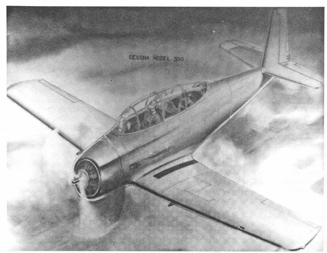
T-28 Trojan Rivals: 1955 USAF MX-955 advanced trainer competition

Do we have a Douglas model number for the proposed XT-30?
 
Probably Model 1068, but that needs confirmation.
 
From Putnam's 'McDonnell Douglas', volume 1, page 609 :-


cheers,
Robin.
 

Attachments

  • Douglas XT_30 - USAF.jpg
    Douglas XT_30 - USAF.jpg
    254.3 KB · Views: 899
  • XT_30 - txt.jpg
    XT_30 - txt.jpg
    189.6 KB · Views: 808
Engine behind the pilot? Sounds like a needlessly-complex beast of an airplane. Any good reason for the mid-mounted engine, aside from CG issues?
 
Presumably sightlines over the nose would much more closely match those of jet aircraft. I can't think of any other reason.
 
You mentioned CG issues, and that sounds accurate. The CG would more closely resemble a jet aircraft.
 
Hi All!

MX-955 proposals:

1) Boeing Model 47? or 48? (?)
2) Bell Model D-? (?)
3) Beech Model ? (?)
4) Bellanca Model ? (?)
5) Convair Model ? (?)
6) Cessna Model 300
7) Curtiss-Wright Model P-5??
8) Douglas Model 1068 or Model 11??---XT-30
9) Fairchilf Model 1?? (?)
10) McDonnell Model 56 (maybe)
11) North American Model 159---XT-28 "Trojan"
12) Republic Model AP-4? (?)
13) Ryan Model ? (?)

...and do so on...

(?)---yes or no
 
Hi All -

Found in the Gerald Balzer Collection is this artwork but I cannot find a reference to a NA T-30. Any suggestions?

Looks more like a Beech to me.

Enjoy the Day! Mark

Just figured out NA means National Archives...
 

Attachments

  • xT-30 X_NA.jpg
    xT-30 X_NA.jpg
    285 KB · Views: 347
Heck, no!! This is NOT a North American! This is the Douglas XT-30, sometimes found as XBT-30, a contender for the MX-1019 specification (and probably designated Model 1068).
 

Attachments

  • Douglas XT-30.gif
    Douglas XT-30.gif
    839.3 KB · Views: 341
Dear Hesham,

I did based on T-30 and NA, thinking North American. Even XT-30 does not bring up your thread as an option. Rather hard to find it when it remains out of the search results.

Nice to see your info though and the image has since been properly labeled.

Enjoy the Day! Mark
 
From Flight dated 22 December 1949:

DOUGLAS XT-30

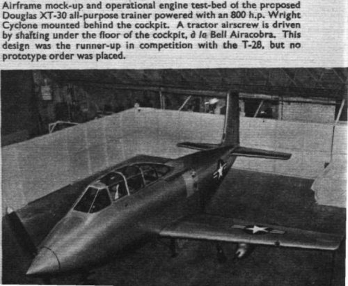
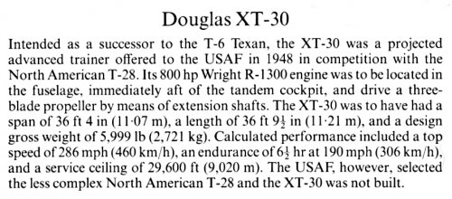
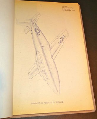
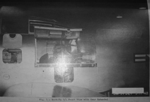
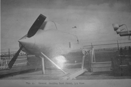
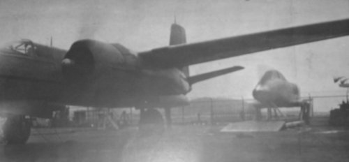
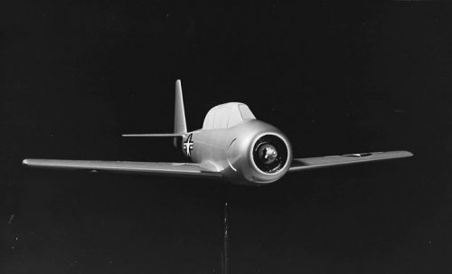
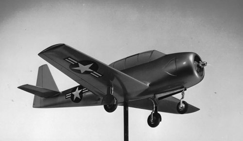
This design proposal (previously illustrated in Flight of December 30th, 1948) was the runner-up to the T-28 in the aforementioned design competition held last year. Although the design study did not materialize even as far as a prototype aircraft, it was considered promising enough to warrant further evaluation, and Douglas were given a half-million-dollar contract to build an experimental mock-up. Perhaps, however, the term " mock-up " does the construction seen in the accompanying illustration less than justice, since in reality it amounted to a fairly complete operational power-plant test-bed to work the bugs out of the submerged engine, with remote airscrew drive, which was the backbone feature of the design.

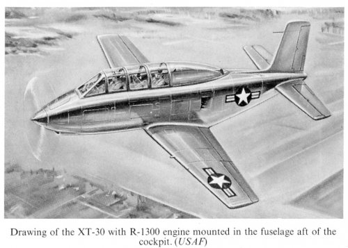
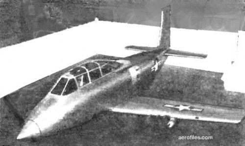
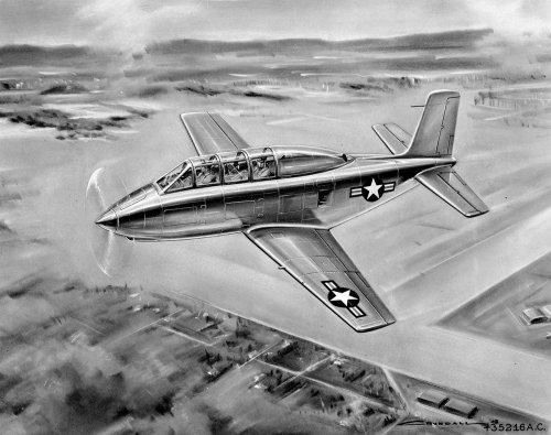
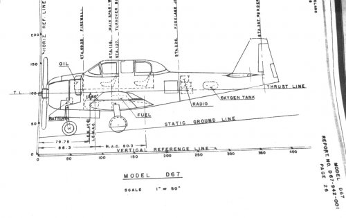
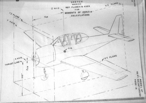
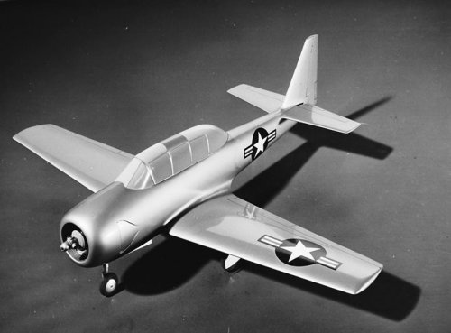
The basic design concept of the XT-30 was a two-seater revival of the Bell P-39 Airacobra formula, wherein the engine is completely buried at mid-fuselage immediately aft of the rear cockpit and over the rear portion of the wing root, the tractor airscrew being driven by an extension shaft under the cockpit floor. An obvious advantage of such a scheme is that, since the engine weight is shifted aft, both tandem seats can be located forward of the wing, thereby giving the occupants an unobstructed forward and downward view over the sharply tapered nose—the kind of view, in fact, that one properly associates with the jet fighter.

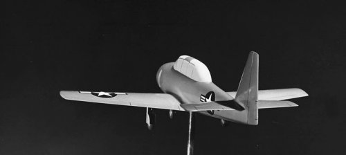
Compared with the orthodox approach exemplified in the T-28, there can be no gainsaying that the XT-30 layout lends itself to a much better (and, therefore, safer) view for both student and instructor ; also that the aerodynamic configuration of the fuselage is markedly superior because of the finer nose-entry and the higher propulsive efficiency of the body-airscrew combination. Another good feature that logically follows from the rear-engine installation is the longer wheelbase of the nose-wheel tricycle landing gear—again the sort of thing that ties in with jet-fighter landing technique and ground-stability characteristics.

From the maintenance standpoint, Douglas engineers claimed that the midship power plant lent itself to improved accessibility of engine and accessories, but on the face of it this seems a bit harder to justify. Admittedly, a six-man maintenance crew had been timed to remove and install an engine in slightly over 20 minutes; however, we suspect that a six-man engine crew for a two-seater trainer would be looked at askance by commercial school-operators. A possible answer might be found in designing the rear half of the fuselage with detachable joints aft of the engine bay, following jet-fighter construction again.

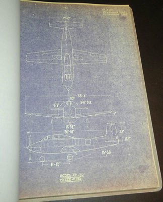
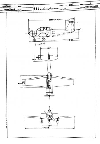
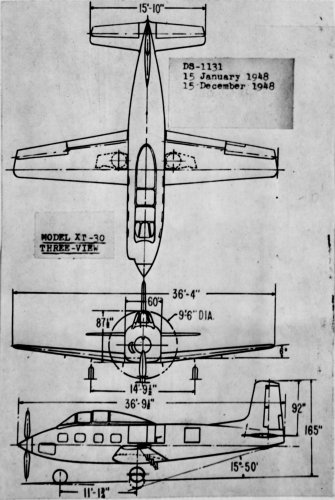
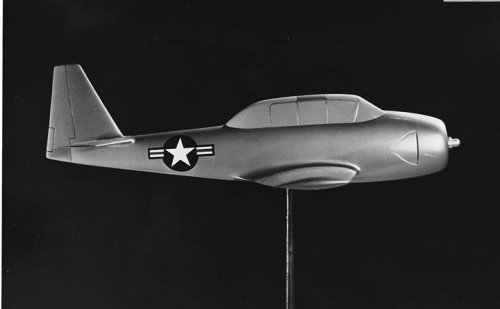
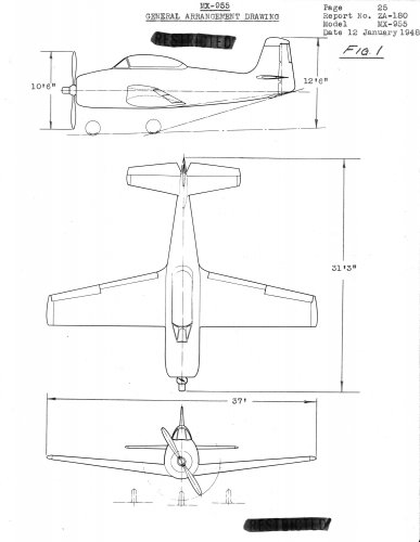
Judging from the view of the mock-up, the XT-30 would have been a clean, square-cut, straightforward low-wing job with a span of 36ft 4in, length of 36ft 10in and overall height of 13ft 7in. The submerged engine was an 800 h.p. Wright R-1300 radial, similar to that installed in the T-28, hence the maximum fuselage-width must have been at least 4ft 6in in the region of the rear cockpit. Cooling, we believe, was arranged through an air scoop on the underside of the nose cowling. Incidentally, looking at the long fuselage nose and bubble canopy forward of the e.g., one cannot help feeling that the vertical tail geometry is shy on dorsal finning.

Estimated performance was a top speed of 286 m.p.h. at ro,oooft, a cruise speed of 190 m.p.h. for 61/4 hours, and a service ceiling of 29,600ft. A picturesque gross weight of 5,999 lb was also quoted, a figure which may be taken as an impressive token of the weight guestimator's art, seeing that the power plant alone (not to mention the rest of the equipment supplied from outside sources) could vary as much as plus or minus 10 lb. Furthermore, since the T-28 is now quoted at 6,759 lb, it is tolerably certain that the XT-30, with its remote airscrew drive, would have scaled something over the 7,000 lb mark—which, no doubt, is impressive hindsight on our part!

Because the airframe designer must perforce make the best of existing power plants within the desired power range, it is no reflection on either the T-28 winner or the XT-30 runner-upto say that they both suffer from the handicap of trying to mate an overgrown seven-cylinder radial engine of 50m diameter with a two-seater tandem cockpit layout, resulting in a body width at least 50 per cent greater than is really necessary or desirable for aerodynamic and vision requirements. Perhaps this sort of excess elbow-room may be more pardonable at the high-powered advanced stage of training, but it strikes us as a bit awe-inspiring for the raw recruit. Indeed, it rather reminds us of the first time we were persuaded to straddle a horse —we were amazed at the enormous expanse of the beast in plan view!

Doubtless it is better to have the chrysanthemum behind, rather than in front of one's face, but nevertheless the submerged-rear-engine scheme is a belated attempt to make the best of the existing engine situation at the expense of engineering complexity, weight and cost. A dozen or so years ago the Bell fighter layout appealed to us very strongly as an outstanding design concept but, to-day, in view of the rapid advance of the turbine art, the logical answer for the pre-jet trainer is obviously the small-diameter turboprop engine on the lines of the A.S. Mamba or the R.R. Dart. We suggest, though, that the power required might be trimmed back to 500 or 600 s.h.p. for a tandem two-seater layout.
 
According to this document that was sold a few months ago on eBay, the specification for the XT-30 was DS-1131, which leads me to believe that the aircraft was probably the Model 1131.
 

Attachments

  • 1.JPG
    1.JPG
    28.8 KB · Views: 509
  • 2.JPG
    2.JPG
    35 KB · Views: 471
  • 3.JPG
    3.JPG
    29.7 KB · Views: 470
  • 4.JPG
    4.JPG
    25 KB · Views: 471
  • 5.JPG
    5.JPG
    17.8 KB · Views: 467
I think you are right Stargazer,


in the same year,the Douglas Model 1126 was appeared in 7/48,so it is logically
to appear of Model 1131 in 1948.
 
More information has emerged on the Douglas XT-30 thanks to more official documents being offered for sale online.
Here are excerpts from a document entitled: Douglas XT-30 Development of Phase I (Final). It was quite long and tough retyping it all from the photos posted online, and there's only a fraction of the whole document, but I believe it is worth it. The XT-30 is a very obscure project and anything that can shed some light on it is most welcome! The designation DS-1131 for the design specification is confirmed. One can only assume that the earlier 1068 designation, described as a trainer series of designs, may have refered to earlier studies that might have led to the XT-30, though it's only guess work on my part.
Anyway, here's the text:

Foreword
This report was prepared by AMC to provide a history of the Phase I development of the XT-30 aircraft. The Phase I study was prepared by Douglas Aircraft Company, Inc., on Contract W33-038-ac-21374, identified by Expenditure Order No. 415-65. The contract was administered Under the direction of the Cargo Branch, Aircraft and Guided Missiles Section, Engineering Division, AMC, Major R. C. Anderson acting as project engineer. This is the final report issued on the project.
Object
The object of the Phase I development of the XT-30 aircraft was to preclude a critical time loss in the trainer program in the event the theoretical deficiencies in the alighting gear geometry of the XT-28 airplane rendered it unsatisfactory. The alighting gear geometry was such that the turn-over angle, due to high center of gravity and location of the nose and main gears, could be critical and ground stability marginal. Due to previous difficulties encountered with submerged engine installations, there was a reluctance to make it a primary choice, so the Phase I program of the XT-30 airplane was intended to prove the submerged engine installation feasible, i. e., that the engine could be cooled during prolonged ground operations and would be no more difficult to maintain than similar aircraft with conventionally mounted engines. Had the ground handling characteristics of the XT-28 airplane been found unsatisfactory during the flight test program, it was intended to terminate that contract and procure XT-30 aircraft with relatively little loss of time.
Summary
As a result of an extensive design competition, initiated in November 1947 and concluded in April 1948, in which fourteen (14) aircraft companies submitted twenty-eight (28) designs, a decision was made to award the following contracts to fulfill the Military Characteristics for Trainer Airplanes, dated 19 September 1947, as amended 19 December 1947.
a. A contract to North American Aviation, Incorporated to provide for design and development of two (2) experimental articles, conforming essentially to the contractor's Model Specification No. NA-48-1270, dated 15 January 1948.
b. A contract to Douglas Aircraft Company, Incorporated to provide for a Phase I (preliminary design and mock-up) program of the XT-30 aircraft to conform essentially to the contractor's Model Specification No. DS-1131, dated 15 January 1948, with special emphasis directed toward cooling the submerged engine installation during ground operation by actually testing a representative engine installation.
The mission of the XT-30 and XT-28 airplanes was to serve as a trainer on which all flying training up to the advanced stages was to be accomplished (including those phases of training formerly known as primary and basic stages) and on which Air Force reserve pilots could maintain flying proficiency. In January 1949, the mission of the XT-30 and XT-28 was modified, and the aircraft will now serve as a trainer in the advanced stages. This change in mission was due to the introduction of a basic trainer (T-31, T-34, T-35, and/or T-6G modernized) (...)
Engine cooling tests
A total of twenty (20) hours of engine test time was conducted in the test rig, and on the basis of the results obtained from these tests, it was concluded that the ground cooling characteristics of the submerged engine installation in the XT-30 aircraft should be satisfactory. The results of these tests are contained in Douglas Reports No. Dev-279 and No. Dev-245.
Procurement
In 1st Indorsement, dated 19 April 1948, to AMC letter dated 2 April 1948, subject, "Evaluation of Trainer and Recommendations on Winning Design", Hq USAF concurred in the Design Evaluation Board recommendation for a Phase I development of an aircraft conforming to Douglas Model Specification No. DS-1131. An authority for Purchase No. 406770 was initiated on 19 May 1948 at an estimated cost of $621,002.00 for the Phase I development consisting of the preliminary design data and drawings, mock-up, and a ground test rig to investigate the cooling characteristics of the submerged engine installation. Contract W33-038-ac-21374 was approved on 28 December 1948, on a cost-plus-fixed-fee basis, estimated cost of $565,456.00, fixed fee of $38,881.92. There were no change orders issued on this contract.
Reports submitted by Douglas to the Air Force:
Number Title
DS-1131 Detail Specification
GS-1165 Mock-up Specification
GS-1166 Wind Tunnel Program Specification
GS-1171 Engineering Data Specification
GS-1172 Handling Aids Specification
GS-1174 Handbook Specification
GS-1175 Tooling Jig and Fixture Specification
Dev-108 Flight Test and Instrumentation Specification
Dev-245 Summary of Tests Conducted on Engine Test Stand
Dev-279 Summary of Cooling Fan Performance Tests on Test Stand
F-216 Finish Specification
SM-13143 Estimated Performance, Stability and Control
SM-13143C Stability and Control Analysis of Wind Tunnel Test Data
SM-13144 Preliminary Stress Analysis
SM-13423 Estimated Weight and Balance and Moments of Inertia
SM-13441 Wind Tunnel Tests of the Carburetor Air Induction System
SM-13443 Numerical and Alphabetical Drawing Indices
SM-13450 Wind Tunnel Tests of the 1/3 Scale Model of the Engine Cooling System

[...]
Description of the aircraft's configuration and main components:
WING
The wing is of all metal, full cantilever, two spar type construction, consisting of inner panels, detachable at the wing-fuselage joint, two detachable angle spar outer wing panels, and two detachable wing tip sections. The sheet metal covering of the wing attaches by means of flush riveting. The inner wing panels each contain a fuel tank bay for the installation of bladder type fuel tanks. The main landing gear is housed in recessed wells of the inner wing panel.
CONTROL SURFACES
The ailerons, elevator, and rudder are all of metal construction with a fabric cover attached to the frame member by use of hollow blind rivets. The horizontal and vertical stabilizers are full cantilever all metal construction consisting of span-wise spars and chord-wise ribs connected to smooth metal sheet covering by the use of flush riveting. Both the horizontal and vertical stabilizers are bolted to the fuselage tail section and are easily removable.
CONTROL SYSTEM
Complete dual flight controls of the stick and pedal type are installed for the pilot and student pilot in accordance with USAF Drawing AD-1. In case of failure of the single cable elevator control system, the aircraft can be landed by the use of the elevator trim tab control. The aileron system is so designed that from the cockpit aft one or all elements leading to one aileron may be destroyed without loss of operation of the other aileron.
FUSELAGE
The fuselage structure is of all metal, semi-monocoque construction incorporating transverse frames and longitudinal stiffeners with smooth exterior sheet metal covering. The fuselage consists of three elements, a front portion providing the cockpits and housing the power plant installation, an aft body portion, and a removable tail section supporting the empennage. The fuselage structure employs aluminum alloy frames and magnesium covering. The section enclosing the power plant is fabricated primarily of stainless steel.
ALIGHTING GEAR
The landing gear is of the retractable tricycle type, incorporating two main wheels, one on each side, mounted aft of the center of gravity, and a nose wheel. Retraction and extension of the landing gear is accomplished hydraulically. In the event of hydraulic system failure, emergency extension can be accomplished by gravity. All components of the landing gear system requiring maintenance are readily accessible.
REMARKS
The unique engine location and power transmission permits greater forward visibility over the nose of the aircraft and the utilization of a landing gear geometry similar to that employed on jet fighter aircraft.
Performance figures:
ESTIMATED PERFORMANCE SUMMARY

Flight Speeds at Design Altitude of 10,000 ft. with Design Gross Weight of 6700 lb. less 1/2 fuel (70 gals.)
  • Maximum Speed 255 at 2600 r.p.m. with 630 b. hp. (114% rated)
  • High Speed 238 at 2400 r.p.m. with 600 b. hp. (100% rated)
  • Operating Speed 165 at 1450 r.p.m. with 272 b. hp. (42% rated)
  • Cruising Speed 150 at 1350 r.p.m. with 239 b. hp. (37% rated)
Maximum range and endurance with 140 gal fuel [and ... lb. bombs] at 10,000' altitude
  • High Speed 248 knots at 3.36 naut or 1.90 hrs. at 74 gal./hr. (s.f.c. 681)
  • Operating Speed 165 knots at 7.38 naut or 6.25 hrs. at 22.5 gal./hr. (s.f.c. 442)
  • Cruising Speed 150 knots at 7.50 naut or 6.96 hrs. at 20.1 gal./hr. (s.f.c. 440)
Practical Range and Endurance with 140 gal fuel [and ... lb. bombs] at 10,000' altitude
  • Operating Speed 165 knots at 7.38 naut or 5.63 hrs. at 22.5 gal./hr. (s.f.c. 442)
  • Cruising Speed 150 knots at 7.50 naut or 6.26 hrs. at 20.1 gal./hr. (s.f.c. 440)
Climb data with Gross Weight of 6,000 lb. less 1/2 fuel (70 gals)
  • Standard altitude ft. SL — 5,000 — 10,000 — 15,000 — 20,000 — 25,000 — 29,600 (service ceiling)
  • Climbing Speed knots 125 — 130 — 135 — 138 — 141 — 144 — 144
  • Engine Speed r.p.m. 2,400 — 2,400 — 2,400 — 2,400 — 2,400 — 2,400 — 2,400
  • Total Power b. hp. 700 — 700 — 600 — 480 — 400 — 350 — 250
  • Maximum Rate f.p.m. 2,700 — 2,500 — 1,750 — 1,300 — 900 — 450 — 100
  • Minimum Rate min. ........ — 2,25 — 4,40 — 7,00 — 11,00 — 20,00 — 37,00
Ceiling: Normal Engine Operation: Service Ceiling 29,600 ft. Absolute Ceiling 30,600 ft.

Take-off and Landing Distances — To Clear 50 ft. Obstacle at Sea Level (no wind).
  • Take-off 1204 ft. at 73,5 knots 25 deg. flap. Gr. Wt. 6000 lb. Ground run 900 ft.
  • Land 1433 ft. at 58.0 knots 50 deg. flap. Gr. Wt. 5582 lb. Ground run 922 ft.
Conclusion (taken from the abstract):
Since the XT-28 aircraft was proven suitable as a trainer aircraft, development of the XT-30 flight article was not undertaken.
 

Attachments

  • Ground Cooling Test Simulating Full Power Climb.jpg
    Ground Cooling Test Simulating Full Power Climb.jpg
    224.5 KB · Views: 159
  • Ground Cooling Test Stand, Three-Quarter View.jpg
    Ground Cooling Test Stand, Three-Quarter View.jpg
    407.7 KB · Views: 157
  • Mock-Up Three-Quarter Front View with Gear Extended.jpg
    Mock-Up Three-Quarter Front View with Gear Extended.jpg
    393.9 KB · Views: 170
Hi All!
I know this project is 2-3 months (Martin Model 244), but I have checked the information and come to this opinion:
Competition of MX-955: 14 companies and 28 proposal:
14 companies:
1) Cessna Model 300
2) Curtiss-Wright Model P-5??
3) Douglas Model 1131---order as XT-30/MX-1019
4) Martin Model 244
5) McDonnell Model 56A, Model 56B
6) North American NA-159---T-28...
7) ? ?
...and do so on...


I think that these companies did not participate (of big companies):
1) Lockheed
2) Grumman
3) Northrop
4) Vought
I think that these companies could participate (of big companies):
1) Boeing
2) Bell
3) Fairchild
4) Convair
5) Republic
And little companies:
1) Beech
2) Ryan


Will be interesting to your opinion too...
 
Bell's design was the D-67.
 

Attachments

  • D-67_01.jpg
    D-67_01.jpg
    91.1 KB · Views: 1,115
  • D-67_02.jpg
    D-67_02.jpg
    198.7 KB · Views: 1,066
  • D-67_03.jpg
    D-67_03.jpg
    94.7 KB · Views: 1,019
hesham said:
Great find Stargazer,
but what is your source ?.


A second hand sales website which we are not supposed to quote in this section of the forum...
 

Attachments

  • image.jpeg
    image.jpeg
    74.8 KB · Views: 146
  • image.jpeg
    image.jpeg
    48.3 KB · Views: 109
  • image.jpeg
    image.jpeg
    24.3 KB · Views: 115
  • image.jpeg
    image.jpeg
    33.4 KB · Views: 599
  • image.jpeg
    image.jpeg
    24.9 KB · Views: 626
Last edited by a moderator:
Good Day All -

A recent acquisition was the stability and control analysis for the Consolidated-Vultee MX-955 entry. Interesting comparison to the XA-41 - would guess they were using wind tunnel data from the XA-41 in support of the MX-955 analysis.

Enjoy the Day! Mark
 

Attachments

  • zConsolidated-Vultee MX-955 General Arrangement Jan-12-48.jpg
    zConsolidated-Vultee MX-955 General Arrangement Jan-12-48.jpg
    250.3 KB · Views: 165
  • zConsolidated-Vultee MX-955 and XA-41 Comparison.jpg
    zConsolidated-Vultee MX-955 and XA-41 Comparison.jpg
    482.4 KB · Views: 193
Brilliant and fantastic find my dear Mark,thanks.
 
Good Day All -

A recent find while working my way thru a collection was this drawing of the McDonnell Model 56 Interior Arrangement. Still looking for further info...

Enjoy the Day! Mark
 

Attachments

  • zMcDonnell Model 56 Interior Arrangement.jpg
    zMcDonnell Model 56 Interior Arrangement.jpg
    804.1 KB · Views: 227
Was this for what the program that became the T-28? I realize you're looking for more info, I'm just curious if it fits the time frame.
 
Was this for what the program that became the T-28? I realize you're looking for more info, I'm just curious if it fits the time frame.
That's the assumption - not anything else out there at that time it would fit into.

Enjoy the Day! Mark
 
From the model list, Model 56 uses the same V-1300 engine as the T-28. Timing also fits the model number.
 
From Cessna Warbirds,

the Model-300 Project.
 

Attachments

  • 1-1.png
    1-1.png
    893.1 KB · Views: 52
  • 2-1.png
    2-1.png
    202.6 KB · Views: 57

Similar threads

Back
Top Bottom