Grey Havoc
ACCESS: USAP
- Joined
- 9 October 2009
- Messages
- 24,500
- Reaction score
- 18,175

Not quite the same tubes. For the initial Polaris Submarines (which I believe never received Trident C4), to meet stringent requirements to protect the missiles from shock in the original Mk 17 Polaris Launch System, the Polaris missile was held by three pads or "stowage launch adaptors" inside the heavy machined steel launch tube, and the launch tube was in turn held in the submarine mount tube by oil-filled double-acting shock absorbers. The oil-filled shock absorbers were fitted as they retained a "null" which required significant force for them to deviate from, this enabling the precise positioning for the optical alignment required to ready the guidance system.
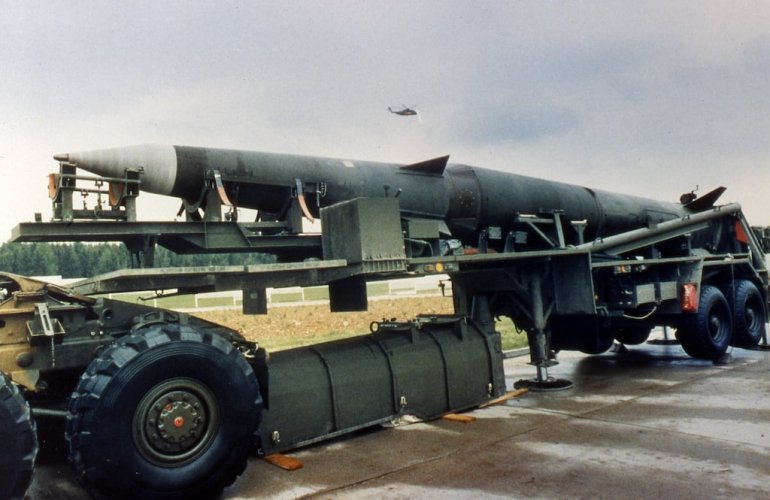
The opportunity to take advantage of a greater proportion of the volume of the submarine mount tube only came as a result of investigating the use of truck-launched Polaris for the MLF. As the original stowage tube was too heavy, and the the stowage launch adaptors were incapable of supporting the missile when stored horizontally on a truck, Westinghouse came up with a design where the missile would be supported by foam-padded resin-reinforced fibreglass panels with heavy duty zippers up the sides which would be undone after the missile was loaded into the launch tube. This would support the missile regardless of orientation and would simultaneously remove the need for the heavy machined launch tube, the launch tube itself now being cushioned by foam springs. A pair of demonstration trucks were built, but when the MLF died, Westinghouse marketed this to the Navy as a means of increasing the number of missiles per submarine (as it would require smaller submarine mount tubes hence more could be installed within a given length). The Special Projects Office realised it would also ensure that larger missiles could be launched from existing tubes.
This later Mk 21 Polaris Launch System would be introduced from James Madison onwards, but would only have the potential for back fitting larger missiles, primarily replacing the liquid springs suspending the launch tube within the mount tube with polyurethane foam, but retaining the liquid springs on which it rested, as were the existing stowage launch adaptors.
The Mk 21 would modified into the Mk 24 for launching Poseidon via a modular replacement with the thin launch tube and padding replacing the earlier machined launch tube and stowage launch adaptors taking full advantage of Westinghouse's innovations for the truck-based MLF system.
Source: From Polaris to Trident, Graham Spinardi
https://www.secretprojects.co.uk/threads/lockheed-smith-miller-hybrid-missile-launch-truck.8990/The artwork suggests that the CL-530 would be launched from a modified commercial tractor and trailer. After reading about the Polaris-armed surface ships disguised as commercial ships, "dummy merchantmen", as part of the MLF, was there an intention to similarly disguise the land-based Polaris launch vehicles as dummy eighteen wheelers?

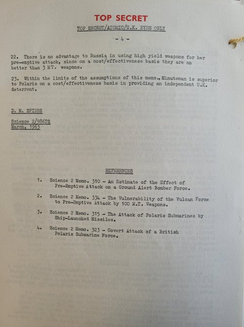
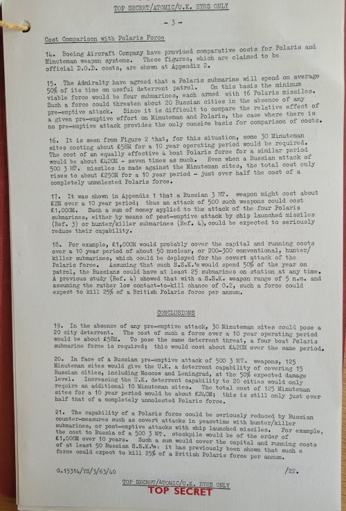
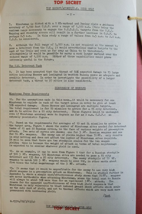
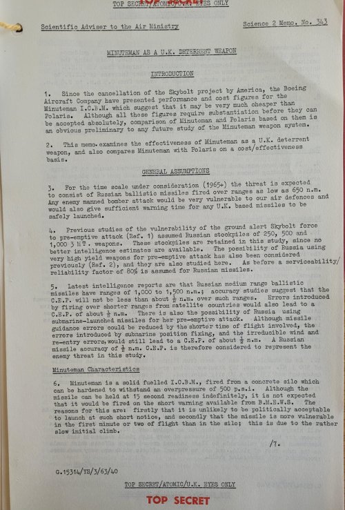
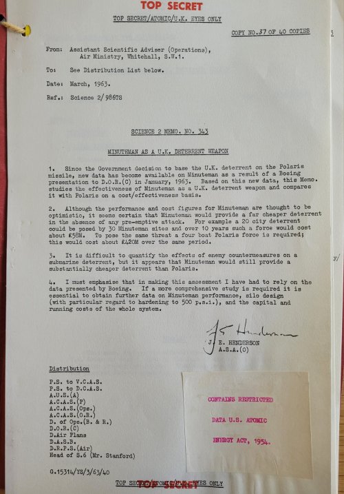
and close withFrom: Assistant Scientific Adviser (Operations), Air Ministry [...]
Minuteman is superior to Polaris
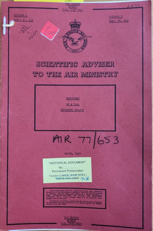
PRO./TNA. AIR 77/653, Minuteman ICBM. for UK. ?, 1963 … https://discovery.nationalarchives.gov.uk/details/r/C11502099
You know, I'd almost swear there were ideas for a medium-ranged Minuteman but with just two stages but I was uncertain about the chronology on that.The MRBM Minuteman was actually the "original" Minuteman. The intended names back in 1958 were Midgetman for the SRBM (only third stage); Minuteman, (first and second stage) MRBM; Sentinel , the ICBM.
Apparently, they'd looked into fitting provisions for the Regulus initially, followed by the PolarisWould have been interesting if Long Beach had recieved the 8 Polaris tubes once planned for it.
I'm always baffled that nobody in the USAF noticed Trident C4 fits neatly in a 40' ISO containerYou know, I'd almost swear there were ideas for a medium-ranged Minuteman but with just two stages but I was uncertain about the chronology on that.
2. More importantly for the USAF, it opens up the natural question of why they shouldn't be assigned to the Army, since they're already operating Pershing IIs.
There would've possibly been a repeat of the mid-1950s USAF/US Army catfight over who gets to control what SSMs.
I'm sure they saw it.I'm always baffled that nobody in the USAF noticed Trident C4 fits neatly in a 40' ISO container
True trueI'm sure they saw it.
But it's designed for the Navy, and the Navy is the enemy.
Is this true for a complete mount with launch gear? Does it still fit in a 40' container?I'm always baffled that nobody in the USAF noticed Trident C4 fits neatly in a 40' ISO container
UGM-96 is (AFAIK) 34.1' (10.39m) long and 6'2" / 74" (1.88m) in diameter. 40' ISO internal dimensions are 39' 4.375" (11.988m) long and 7' 7.73" (2.330m) wide, with heights between 7'2.5" (2.197m) and 8'8.5" (2.665m).Is this true for a complete mount with launch gear? Does it still fit in a 40' container?
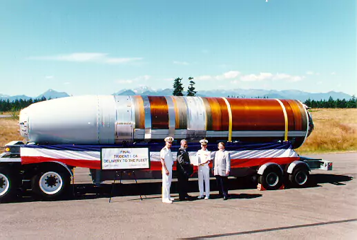
I lean the other way. This was used for the Pershing II. UGM-96 is the same length, almost twice as wide and 4.5 times heavier. The erector would have to be much beefier. Also, either use a launch tube to eject the missile or the container needs to have holes for exhaust. This and missile mass would make it hard to fit in in the container.UGM-96 is (AFAIK) 34.1' (10.39m) long and 6'2" / 74" (1.88m) in diameter. 40' ISO internal dimensions are 39' 4.375" (11.988m) long and 7' 7.73" (2.330m) wide, with heights between 7'2.5" (2.197m) and 8'8.5" (2.665m).
This means there's ~450mm (~17.7") clearance in width and ~1.6m (~5'2") in length from the interior dimensions of a standard ISO container. The external dimensions are 12.192m x 2.438m, which gives a clearance of ~1.8m and 558mm, respectively. I haven't done any detailed engineering analysis, but to my eye it seems at least plausible to fit the launch equipment in that space.
Polaris is cold-launched, so it doesn't need a particularly thick tube for pressure resistance. ~50psi.I lean the other way. This was used for the Pershing II. UGM-96 is the same length, almost twice as wide and 4.5 times heavier. The erector would have to be much beefier. Also, either use a launch tube to eject the missile or the container needs to have holes for exhaust. This and missile mass would make it hard to fit in in the container.
Only reason it's a thick tube is to resist sea pressure.It is cold launched from a thick tube. Outside this it should be launched hot like Pershing.
MX and SICBM were cold launched.Polaris is cold-launched, so it doesn't need a particularly thick tube for pressure resistance. ~50psi.
I mean, it's a shitload more capability than P2! 8RVs to ±7400km! It just about fits dimensionally in a way that is useful for helping people conceptualize how big it is. If you want a TEL I think you're looking at something maybe in the 45' or 53' high cube size.I lean the other way. This was used for the Pershing II. UGM-96 is the same length, almost twice as wide and 4.5 times heavier. The erector would have to be much beefier. Also, either use a launch tube to eject the missile or the container needs to have holes for exhaust. This and missile mass would make it hard to fit in in the container.
You can use a piston plate and black powder!Only reason it's a thick tube is to resist sea pressure.
No sea pressure, no need for thick tube. Just one thick enough to survive the cold launch, which works out to maybe 20psi.
You would need to do a little redesign to the cold-launch manifold, though. The usual setup is a roughly water heater sized gas generator next to the tube. You'd need to move the gas generator to below the tube.
But again, the problem is that Polaris is a Navy program, and at least the USAF would not touch a Navy program without an order from God. Or at least the SecDef.
I was going for minimal changes from the USN design.You can use a piston plate and black powder!

I have also discussed the next item, the MMRBM, in connection with the General Purpose Forces program. Late in fiscal year 1962, $4 million was reprogrammed and applied to this project to commence Phase I—program definition. The Congress provided $80 million for fiscal year 1963, of which $12 million has been applied to complete the program definition phase and $30 million will be available for Phase II. Practically all of the balance of the $80 million has been applied to the "Stellar Inertial Guidance" project which I discussed earlier, of which $36 million is directly applicable to the MMRBM.
The $150 million requested for fiscal year 1964 would continue full-scale development of this missile. Present planning parameters for this weapon system shape up as follows: a two-stage, solid propellant missile weighing approximately 12,500 pounds with a maximum range of about 2,000 nautical miles. A stellar inertial guidance system should give it a CEP of [REDACTED]. A simplified, all-inertial system is also possible depending on how the operational requirements and technical developments trade off. The missile and necessary support equipment are to be suitable for deployment in a single vehicle capable of operating over all primary and most secondary roads in Europe, as well as from surface ships.
One word of caution: no decision has yet been made to produce and deploy this weapon. Nevertheless, I believe it would be a good investment to proceed with the development at this time since we may need a weapon of this sort to fill the range gap between the PERSHING and the ICBM's.
American surface-to-surface ballistic missile, development started in 1961. Program cancelled in 1965.
AKA: Mobile Mid-Range Ballistic Missile;TMRBM;Transportable Mid-Range Ballistic Missile. Status: Cancelled 1964. Gross mass: 5,440 kg (11,990 lb). Height: 7.01 m (22.99 ft). Diameter: 1.37 m (4.49 ft).
The Mobile Mid-Range Ballistic Missile (MMRBM) would have the range to reach targets in the Soviet Union or China from land and surface ship deployment in Western Europe or Far East. Evidently it was to be a replacement for the fixed Thor and Jupiter missiles. But while development was underway, this class of missiles were being removed under a secret agreement with the Russians that resolved the Cuban missile crisis. Secretary of Defense McNamara used the existence of MMRBM as grounds for cancelling the Mobile Minuteman project. However MMRBM in turn never received substantial Congressional or Presidential support. One final look at the project in 1964 to save costs was dubbed the Transportable Mid-Range Ballistic Missile. This used the second and third stages of the Minuteman instead of a new development. Out of money and out of support, the project was cancelled in 1965.
An MRBM Force.
We are prepared to enter into a detailed discussion of the need for an MRBM force in the Permanent Council as soon as possible after this meeting. We will then be ready to discuss the full range of technical, military and political problems that would be associated with such a force. We expect our allies will wish to consider very carefully the full implications of undertaking this venture. There are many complicated questions to be dealt with. In the meantime the U.S. although it is not committed to the procurement or deployment of an MRBM weapon system, is proceeding with the design of such a weapon. Certain of the technical specifications of the weapon we have under development are listed in the attached Appendix.
Summary Data on Missile "X"
Range: 2000 n.mi
CEP: about 1000 feet (land based) at 1000 n. mi.
CEP: about 1700 feet (sea based) at 1000 n. mi.
Warhead yield: DELETED
Missile gross weight 12,000 lbs
Method of operation: surface ship mobile or road mobile to be determined in the light of numerous factors
Cost for 250 missiles about $2 billion
FY 1963 amount programmed by the U.S. for research and development $80 million
Availability: Assuming a production decision by 1 July 1963 operational deployment would begin in 1966.