FighterJock
ACCESS: Above Top Secret
- Joined
- 29 October 2007
- Messages
- 6,717
- Reaction score
- 7,952
Would putting an AESA radar into the AIM-260 be the first use of AESA in an air to air missile or have there been attempts before? 

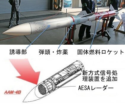
AAM-4B has an AESA seeker.Would putting an AESA radar into the AIM-260 be the first use of AESA in an air to air missile or have there been attempts before?
Pretty extensive documentation on the AAM-4B. The ranges are in the classified supplement but the graphs are present.
Not that I’ve found unfortunately but most of the juicy stuff besides the envelopes are on page 27+Is there any way to auto-translate the document into English?
Abstract]
[Problem] To provide a guidance device that can constantly maintain optimal acceleration of a flying object, enabling smooth guidance of the flying object.
Solution] A fuzzy acceleration command calculation circuit (11) is provided that evaluates the rate of change of the line of sight angle and the approach speed between the flying object and a target object using fuzzy functions incorporating human experience, and calculates an acceleration command for the flying object based on these evaluation results using fuzzy inference.
[Claims]
[Claim 1] The radar system comprises an antenna that transmits radar waves in the direction of a target object and receives reflected waves; a radar transmitter that generates high-frequency power at the antenna; a radar receiver that amplifies the signal received from the antenna; a frequency mixer that compares the frequency of the radar receiver's received signal with the frequency of the radar transmitter's high-frequency power and detects the frequency difference as a Doppler frequency; an angular error detection circuit that receives the radar receiver's received signal and detects the angular error of the antenna relative to the target; a swing angle detection circuit that detects the angle of the antenna relative to the aircraft; an antenna angular velocity detection sensor that detects the angular velocity movement of the antenna; and an antenna spatial stabilization circuit that spatially stabilizes the antenna based on the output signal of the swing angle detection circuit and the angular velocity output from the antenna angular velocity detection sensor, and angularly tracks the antenna in the direction of the target object based on the output signal of the angle error detection circuit. and a drive circuit; an acceleration command calculation circuit that outputs a vehicle acceleration command based on the output from the angle error detection circuit and the Doppler signal from the frequency mixer; an acceleration sensor and an angular velocity sensor that detect the acceleration and angular velocity of the vehicle; an autopilot that outputs a rudder angle command to the control surfaces based on the acceleration sensor and angular velocity sensor outputs and the acceleration command calculation circuit output signal; and a steering device that controls the surfaces based on the steering command. The acceleration command calculation circuit has a fuzzy acceleration command calculation circuit that implements predetermined fuzzy functions and fuzzy inference rules based on human experience and defuzzification processing, and the fuzzy acceleration command calculation circuit calculates an acceleration command for the vehicle based on the output from the angle error detection circuit and the Doppler signal. [Claim 2] The missile guidance system of claim 1 further comprises a distance detection circuit that calculates the relative distance between the missile and the target from the time difference between the transmitted and received waves, and a fuzzy acceleration command calculation circuit that evaluates the output from the distance detection circuit, the output signal from the angle error detection circuit, and the Doppler frequency using a fuzzy function incorporating human experience, performs fuzzy inference based on the evaluation results, and calculates an acceleration command for the missile by defuzzifying the inference results. [Claim 3] A radar system comprising: an antenna for transmitting radar waves in the direction of a target object and receiving reflected waves; a radar transmitter for generating high-frequency power at the antenna; a radar receiver for amplifying the signal received from the antenna; a frequency mixer for comparing the frequency of the radar receiver's received signal with the frequency of the radar transmitter's high-frequency power and detecting the frequency difference as a Doppler frequency; an angle error detection circuit for receiving the radar receiver's received signal and detecting the angular error of the antenna relative to the target; a swing angle detection circuit for detecting the angle of the antenna relative to the aircraft; an antenna angular velocity detection sensor for detecting the angular velocity of the antenna; and an output signal from the swing angle detection circuit.
A missile guidance system comprising: an antenna spatial stabilization and drive circuit that spatially stabilizes the antenna based on the angular velocity output from the antenna angular velocity detection sensor and the angular velocity output from the antenna angular velocity detection sensor, and angularly tracks the antenna in the direction of a target object based on the output signal of the angle error detection circuit; a fuzzy acceleration command calculation circuit that evaluates the antenna's swing angular velocity from the antenna angular velocity detection sensor and the Doppler frequency from the frequency mixer using a fuzzy function incorporating human experience, performs fuzzy inference based on the evaluation results, and calculates an acceleration command for the missile by defuzzifying the inference results; an acceleration sensor and angular velocity sensor that detect the acceleration and angular velocity of the missile; an autopilot that outputs a rudder angle command to the control surfaces based on the outputs of the acceleration sensor and angular velocity sensor and the output signal of the acceleration command calculation circuit; and a steering device that controls the surfaces based on the steering command.
Claim 4 The system comprises an antenna that receives reflected waves of radar transmission waves emitted from an external device of the vehicle toward a target object; a radar receiver that amplifies the received signal from the antenna; a frequency mixer that compares the received signal from the radar receiver with the frequency of the high-frequency power in the external device and detects the frequency difference as a Doppler frequency; an angle error detection circuit that receives the received signal from the radar receiver and detects the angular error of the antenna relative to the target; a swing angle detection circuit that detects the angle of the antenna relative to the aircraft; an antenna angular velocity detection sensor that detects the angular velocity movement of the antenna; and an antenna spatial stabilization and drive circuit that spatially stabilizes the antenna based on the output signal of the swing angle detection circuit and the angular velocity output from the antenna angular velocity detection sensor, and angularly tracks the antenna toward the target object based on the output signal of the angle error detection circuit. a guidance system for a vehicle comprising: an acceleration command calculation circuit that outputs a vehicle acceleration command based on the output from the angle error detection circuit and the Doppler signal from the frequency mixer; an acceleration sensor and an angular velocity sensor that detect the vehicle's acceleration and angular velocity; an autopilot that outputs a rudder angle command to the control surfaces based on the output from the acceleration sensor and the angular velocity sensor and the output signal from the acceleration command calculation circuit; and a steering device that controls the surfaces based on the steering command; wherein the acceleration command calculation circuit includes a fuzzy acceleration command calculation circuit that implements predetermined fuzzy functions and fuzzy inference rules based on human experience and defuzzification processing, and the fuzzy acceleration command calculation circuit calculates an acceleration command for the vehicle based on the output from the angle error detection circuit and the Doppler signal. [Claim 5] An antenna for receiving reflected waves of radar transmission waves irradiated from an external device of a flying vehicle onto a target object; a radar receiver for amplifying the received signal from said antenna; a frequency mixer for comparing the received signal from said radar receiver with the frequency of high-frequency power in said external device and detecting the frequency difference as a Doppler frequency; an angle error detection circuit for receiving the received signal from said radar receiver and detecting an angular error of the antenna relative to the target; a swing angle detection circuit for detecting the angle of said antenna relative to the aircraft; an antenna angular velocity detection sensor for detecting the angular velocity movement of said antenna; an antenna spatial stabilization and drive circuit for spatially stabilizing the antenna based on the output signal of said swing angle detection circuit and the angular velocity output from said antenna angular velocity detection sensor and for angularly tracking said antenna in the direction of the target object based on the output signal of said angle error detection circuit; and a frequency mixer for detecting the antenna swing angular velocity from said antenna angular velocity detection sensor and the angular velocity of said antenna relative to the target object. A missile guidance system comprising: a fuzzy acceleration command calculation circuit that evaluates Doppler frequencies from a wavenumber mixer using fuzzy functions incorporating human experience, performs fuzzy inference based on the evaluation results, and defuzzifies the inference results to calculate an acceleration command for the missile; an acceleration sensor and an angular velocity sensor that detect the missile's acceleration and angular velocity; an autopilot that outputs a rudder angle command to the control surfaces based on the outputs of the acceleration sensor and angular velocity sensor and the output signal of the acceleration command calculation circuit; and a steering device that controls the wings based on the steering command.
Claim 6 An infrared receiving antenna for receiving infrared radiation emitted from a target object, a signal processor for processing the received signal from the infrared antenna, an angular error detection circuit for detecting the angular error of the infrared receiving antenna relative to the target based on the signal from the signal processor, a swing angle detection circuit for detecting the angle of the infrared receiving antenna relative to the aircraft, an antenna angular velocity detection sensor for detecting the angular velocity movement of the infrared receiving antenna, an antenna spatial stabilization and drive circuit for spatially stabilizing the infrared receiving antenna based on the output signal of the swing angle detection circuit and the angular velocity output from the antenna angular velocity detection sensor, and simultaneously angularly tracking the infrared receiving antenna in the direction of the target object based on the output signal of the angular error detection circuit, and an angular error detection circuit. A guidance system for a flying object, comprising: an acceleration command calculation circuit that outputs a flying object acceleration command based on output from a path; an acceleration sensor and an angular velocity sensor that detect the acceleration and angular velocity of the flying object; an autopilot that outputs a rudder angle command to the control surfaces based on the acceleration sensor and angular velocity sensor outputs and the output of the acceleration command calculation circuit; and a steering device that controls the surfaces based on the steering command. The acceleration command calculation circuit has a fuzzy acceleration command calculation circuit that implements predetermined fuzzy functions and fuzzy inference rules based on human experience and defuzzification processing, and the fuzzy acceleration command calculation circuit calculates an acceleration command for the flying object based on the output signal from the angle error detection circuit.
[Detailed Description of the Invention]
[0001]
[Technical Field of the Invention] This invention relates to a guidance system for a flying object that is guided toward a target object.
[0002]
[Background Art] First, a conventional active guidance system for a flying object will be described with reference to Figure 21. In the figure, 1 is the antenna, 21 is the flying object, 22 is the target object, 23 is the radar transmission wave, 24 is the radar reception wave and the direction of the target as seen from the flying object, i.e., the line of sight, 25 is a predetermined reference line, 26 is the flying object's axis, Vm is the flying object's velocity vector, Am is the flying object's acceleration vector generated perpendicular to Vm, Vt is the target's velocity vector, σ is the line of sight angle between the line of sight 24 and the reference line 25, λ is the antenna swing angle between the flying object's axis 26 and the antenna, and a is the angle of attack between the flying object's velocity vector Vm and the flying object's axis 26.
In the above configuration, the flying object 21, traveling at a velocity Vm in a direction angle a relative to the axis direction 26 of the flying object 21, transmits radar transmission waves 23 from antenna 1 toward a target object 22 traveling at a velocity Vt. The radar transmission waves 23 reflected by the target object 22 are received as radar reception waves 24. The line of sight angle σ can be calculated from the angular difference between the direction in which antenna 1 receives the radar reception waves 24 and a preset reference line 25, and the rate of change of the line of sight angle σ can be calculated from its change over time. The closing speed of the target object 22 and the flying object 21 can be calculated from the frequency difference between the radar transmission waves 23 transmitted by antenna 1 and the received radar reception waves 24, i.e., the Doppler frequency. Finally, the distance between the target object 22 and the flying object 21 can be calculated from the time difference between the transmission of the radar transmission waves 23 by antenna 1 and the reception of the radar reception waves 24. In order for the flying object 21 to rendezvous with the target object 22, it must generate acceleration Am perpendicular to the velocity vector Vm of the flying object 21 in accordance with the behavior of the target object 22, and constantly correct its trajectory. Conventional flying object guidance systems use a guidance law known as proportional navigation to calculate the acceleration Am required for the flying object 21 to rendezvous with the target object 22.
Next, proportional navigation will be explained using Figure 22. In Figure 22, 21 is the flying object, 22 is the target object, 24 is the line of sight, 25 is the reference line, Vm is the velocity vector of the flying object 21, and Vmc is the line of sight direction component of the velocity vector Vm.
Vmn is the component of velocity vector Vm perpendicular to Vmc, Vt is the velocity vector of target object 22, Vtc is the line-of-sight component of velocity vector Vt, Vtn is the component of velocity vector Vt perpendicular to Vtc, and Am is the acceleration of vehicle 21 generated perpendicular to Vm.
It is known that a vehicle can meet the target if it flies while maintaining a constant line-of-sight angle of the target object as seen from the vehicle. To achieve this, typical vehicle guidance systems multiply the rate of change of the line-of-sight angle by the approach velocity Vc,
and then multiply this by the navigation constant n to calculate the acceleration command for the vehicle, as shown in equation (1).
(4) JP 9-236400
5 6
This equation (1) is the commonly known proportional navigation equation. The approach velocity Vc can be expressed as the sum of Vmc and Vtc in Figure 22. However, in an actual aircraft, as mentioned previously, it is determined by measuring the Doppler frequency, i.e., the difference in frequency between the radar transmission wave 23 and the radar reception wave 24 in Figure 21.
[Equation 1]
[0007] The specific configuration and operation of a conventional guided aircraft will be explained. Figure 23 is a diagram of a conventional guided aircraft. 1 is the antenna, 2 is the oscillation angle detection circuit,
3 is the antenna angular velocity detection sensor, 4 is the antenna spatial stabilization and drive circuit, 5 is the directional coupler, 6 is the radar transmitter, 7 is the radar receiver, 8 is the frequency mixer, 9 is the angle error detection circuit, 14 is the autopilot, 15 is the steering system, 16 is the aircraft, 17 is the acceleration and angular velocity sensor, and 27 is the acceleration command calculation circuit.
Next, operation will be explained with reference to Figures 21 and 23. High-frequency power output from radar transmitter 6 (Figure 23) is fed to antenna 1 through directional coupler 5, becoming radar transmission wave 23 (Figure 21), which is radiated toward target object 22. This radar transmission wave 23 is reflected by target object 22, becoming radar reception wave 24, which is received by antenna 1. Antenna 1 converts radar reception wave 24 into an electrical signal and sends it to radar receiver 7 via directional coupler 5. Radar receiver 7 amplifies this electrical signal and outputs it to angle error detection circuit 9 and frequency mixer 8. The angle error detection circuit 9 receives this electrical signal, detects the angular error of the antenna relative to the target, and outputs it to antenna spatial stabilization and drive circuit 4. Meanwhile, the antenna spatial stabilization and drive circuit 4 receives the antenna swing angle signal obtained from the antenna swing angle detection circuit 2, the signal from the antenna angular velocity detection sensor 3 mounted on the antenna, and the signal from the angle error detection circuit 9, and tracks the angle of the antenna 1 toward the target object 22 (Figure 21) so that the strength of the received signal from the radar receiver 7 is maximized.
The received signal from the radar receiver 7 is sent to the frequency mixer 8, where it is compared in frequency with the radar transmission frequency of the radar transmitter 16, and the difference between the two frequencies is output as a Doppler frequency.
The angle error signal obtained from the angle error detection circuit 9 is combined with the Doppler frequency obtained from the frequency mixer 8, which is proportional to the relative closing speed between the guided vehicle 21 and the target object 22, and the acceleration command required for guidance is synthesized in the acceleration command calculation circuit 27 according to the proportional navigation equation described above. [0012] Furthermore, the acceleration command output from the acceleration command calculation circuit 27 and the aircraft acceleration and angular velocity measured by the acceleration sensor and angular velocity sensor 17 are input to the autopilot 14, where they are compared to produce a rudder angle command signal.
[0013] The rudder angle command output from the autopilot 14 is sent to the steering device 15, which steers in accordance with the command, thereby making the necessary trajectory corrections and guiding the aircraft 16 to the target.
[0014] Next, the semi-active guidance method will be explained using Figure 24. In the diagram, 1 is the antenna, 21 is the aircraft, 22 is the target object, 28 is the aircraft transmitting radar waves toward the target, 23 is the radar transmission wave, 24 is the radar reception wave and the direction of the target as seen from the aircraft, i.e., the line of sight, 25 is a predetermined reference line, 26 is the aircraft's axis,
Vm is the aircraft's velocity vector, Am is the aircraft's acceleration vector generated perpendicular to Vm, Vt is the target's velocity vector, σ is the line of sight angle between the line of sight 24 and the reference line 25, λ is the antenna pitch angle between the aircraft's axis 26 and the antenna, and a is the angle of attack between the aircraft's velocity vector Vm and the aircraft's axis 26. In the above configuration, aircraft 28 transmits radar transmission waves 23 toward target object 22 traveling at a speed Vt, and receives radar transmission waves 23 reflected by target object 22 as radar reception waves 24. The line of sight angle σ can be calculated from the angular difference between the direction in which antenna 1 receives radar reception waves 24 and a preset reference line 25, and the rate of change of line of sight angle σ can be calculated from its change over time. The closing speed of target object 22 and aircraft 21 can be calculated from the frequency difference (i.e., Doppler frequency) between radar transmission waves 23 transmitted by antenna 1 and received radar reception waves 24. Finally, the distance between target object 22 and aircraft 21 can be calculated from the time difference between when antenna 1 transmits radar transmission waves 23 and when it receives radar reception waves 24. To rendezvous with the target object 22, the flying object 21 must generate acceleration Am perpendicular to the flying object's velocity vector Vm in accordance with the target object's behavior, thereby constantly correcting its trajectory.
Conventional flying object guidance systems use the proportional navigation method described above to calculate the acceleration Am required for the flying object 21 to rendezvous with the target object 22. In this figure,
(5) JP 9-236400
7 8
radar transmission wave 23 is transmitted from an aircraft, but it can also be from a ground-based radar transmission facility or a ship's radar transmission facility.
Next, using Figure 25, we will explain the passive guidance method. In the figure, 21 is the flying vehicle, 22 is the target object, 25 is a predetermined reference line, 26 is the vehicle's axis, 29 is infrared radiation emitted from the target object 22 toward the flying vehicle 21 and is the direction of the target as seen from the flying vehicle, i.e., the line of sight, 19 is the antenna for receiving the infrared radiation emitted from the target object 22, Vm is the flying vehicle's velocity vector, Am is the flying vehicle's acceleration vector generated perpendicular to Vm, Vt is the target's velocity vector, σ is the line of sight angle between the line of sight 29 and the reference line 25, λ is the antenna swing angle between the flying vehicle's axis 26 and the antenna 19, and a is the angle of attack between the flying vehicle's 21 velocity vector Vm and the flying vehicle's axis 26. In the above configuration, the missile 21, traveling at a velocity Vm in a direction angle a relative to the missile's axis 26, receives infrared rays 29 emitted from a target object 22 traveling at a velocity Vt with the infrared receiving antenna 19. The line-of-sight angle σ can be measured from the angular difference between the direction in which the receiving antenna 19 receives the infrared rays 29 and a preset reference line 25. Furthermore, the rate of change of the line-of-sight angle can be calculated from the change over time. Like active guidance missiles, passive guidance missiles must generate an acceleration Am perpendicular to the missile's velocity vector Vm in order to intercept the target object 22, thereby constantly correcting their trajectory. However, unlike active guidance systems, passive guidance systems for air vehicles only obtain angular information from the target. Therefore, when using the proportional navigation formula shown in equation (1), the approach velocity Vc is generally treated as an estimated value, and the acceleration Am required for the air vehicle 21 to rendezvous with the target object 22 is calculated.
[Problem to be Solved by the Invention] Conventional active guidance systems for air vehicles calculate the required acceleration of the air vehicle by multiplying the line of sight angle change rate and approach velocity Vc by the navigation constant n. Therefore, the air vehicle's acceleration is proportional to the line of sight angle change rate and approach velocity Vc, which may not always be optimal. Furthermore, in conventional passive guidance systems for missiles, as with active guidance systems, the required missile acceleration is calculated by multiplying the estimated rate of change of the line-of-sight angle and the approach velocity Vc by the navigation constant n. As a result, the missile's acceleration is proportional to the rate of change of the line-of-sight angle and the approach velocity Vc, and may not always be optimal.
The purpose of this invention is to solve the above-mentioned problems and to provide a missile guidance system that can guide a missile to a target object more smoothly than conventional missile guidance systems using relative navigation.
[Means for Solving the Problems] The missile guidance device of this invention solves the above-mentioned problems by using a fuzzy acceleration command calculation circuit that, instead of the conventional proportional navigation-based acceleration command calculation circuit, evaluates the rate of change of the line-of-sight angle and the approach speed between the missile and the target object using fuzzy functions that incorporate human experience. Based on these evaluation results, the fuzzy value of the acceleration command to the missile is calculated by performing fuzzy inference, and the inference results are defuzzified to calculate the acceleration command to the missile. [0022] Furthermore, the missile guidance system of this invention calculates the missile's required acceleration to guide it toward a target object. Instead of using a conventional acceleration command calculation circuit that uses proportional navigation, this circuit uses a fuzzy acceleration command calculation circuit that evaluates the rate of change of the line of sight angle, the approach speed between the missile and the target object, and the relative distance between the missile and the target object using fuzzy functions that incorporate human experience. Based on these evaluation results, the fuzzy value of the acceleration command to the missile is determined by performing fuzzy inference, and the inference results are defuzzified to calculate the acceleration command to the missile. [0023] The missile guidance device of this invention solves the above-mentioned problems by using a fuzzy acceleration command calculation circuit, instead of the conventional proportional navigation-based acceleration command calculation circuit, to calculate the amount of acceleration required to guide the missile toward a target object. The circuit evaluates the rate of change of the antenna swing angle and the approach speed between the missile and the target object using fuzzy functions that incorporate human experience, and then performs fuzzy inference to determine the fuzzy value of the acceleration command to the missile based on the evaluation results. The inference results are then defuzzified to calculate the acceleration command to the missile. [0024] Furthermore, the missile guidance device of this invention solves the above-mentioned problems by using a fuzzy acceleration command calculation circuit that, instead of the conventional proportional navigation-based acceleration command calculation circuit, evaluates the rate of change of the line of sight angle and the approach speed between the missile and the target object using fuzzy functions incorporating human experience, and based on these evaluation results, determines the fuzzy value of the acceleration command to the missile by performing fuzzy inference. The inference results are then defuzzified to calculate the acceleration command to the missile.
(6) JP 9-236400
9 10
The missile guidance device of this invention, instead of the conventional proportional navigation-based acceleration command calculation circuit, calculates the acceleration command to the missile.
This problem is solved by using a fuzzy acceleration command calculation circuit that, instead of using proportional navigation, evaluates the rate of change of the antenna swing angle and the approach speed between the aircraft and the target object using fuzzy functions incorporating human experience, and calculates the fuzzy acceleration command value for the aircraft based on these evaluation results using fuzzy inference. The inference results are then defuzzified to calculate the acceleration command for the aircraft.
The aircraft guidance device of this invention calculates the amount of acceleration required to guide the aircraft toward the target object by using a fuzzy acceleration command calculation circuit that, instead of using a conventional proportional navigation acceleration command calculation circuit, evaluates the rate of change of the line of sight angle using fuzzy functions incorporating human experience, and calculates the fuzzy acceleration command value for the aircraft based on these evaluation results using fuzzy inference. The inference results are then defuzzified to calculate the acceleration command for the aircraft. [0027]
[Embodiments of the Invention]
Embodiment 1. One embodiment of the present invention will be described using Figures 1 to 5. Figure 1 shows the configuration of embodiment 1, in which reference numeral 1 denotes an antenna, 2 denotes a swing angle detection circuit, 3 denotes an antenna angular velocity detection sensor, 4 denotes an antenna spatial stabilization and drive circuit, 5 denotes a directional coupler, 6 denotes a radar transmitter, 7 denotes a radar receiver, 8 denotes a frequency mixer, 9 denotes an angle error detection circuit, 10 denotes a fuzzy acceleration command calculation circuit, 11 denotes a fuzzification processing unit within the fuzzy acceleration command calculation circuit, 12 denotes a fuzzy inference implementation unit within the fuzzy acceleration command calculation circuit, 13 denotes a defuzzification processing unit within the fuzzy acceleration command calculation circuit, 14 denotes an autopilot, 15 denotes a steering system, 16 denotes an aircraft, and 17 denotes an acceleration and angular velocity sensor. Figure 2 shows fuzzy functions, or membership functions, incorporated into the fuzzification processing unit 11, that incorporate human experience for the rate of change of the gaze angle between the missile and the target and the approach velocity. In the figure, PB represents a positive large value, PM represents a positive medium value, PS represents a positive small value, ZR represents zero, NS represents a negative small value, NM represents a negative medium value, and NB represents a negative large value, providing an evaluation based on human experience of the rate of change of the gaze angle and the approach velocity of the missile.
Figure 3 shows fuzzy rules for implementing fuzzy inference incorporated into the fuzzy inference implementation unit 12. These rules determine the fuzzy value of the amount of missile acceleration in response to the evaluation results of the rate of change of the gaze angle and the approach velocity. Figure 4 shows the membership function for acceleration values used by the defuzzification processing unit 13, which grades the fuzzy acceleration values inferred by the fuzzy rules using human experience. In the figure, PB represents a positive high, PM represents a positive medium, PS represents a positive low, ZR represents zero, NS represents a negative low, NM represents a negative medium, and NB represents a negative high. Figure 5(a) illustrates the defuzzification method used by the defuzzification processing unit 13, showing the means for quantifying the determined acceleration grade as a control variable.
Next, the operation of the above embodiment will be explained using Figures 1 through 9 and 21. High-frequency power output from the radar transmitter 6 (Figure 1) is fed to the antenna 1 through the directional coupler 5, and is radiated toward the target object 22 as the radar transmission wave 23 (Figure 21). This radar transmission wave 23 is reflected by the target object 22, becoming a radar reception wave 24, which is received by antenna 1. Antenna 1 converts the radar reception wave 24 into an electrical signal and sends it to radar receiver 7 via directional coupler 5 (see Figure 1). Radar receiver 7 amplifies this electrical signal and outputs it to angle error detection circuit 9 and frequency mixer 8. The angle error detection circuit 9 receives this electrical signal, detects the angular error of the antenna relative to the target, and outputs the signal to antenna spatial stabilization and drive circuit 4. Meanwhile, antenna spatial stabilization and drive circuit 4 receives the antenna swing angle signal obtained from antenna swing angle detection circuit 2, the signal from antenna angular velocity detection sensor 3 mounted on the antenna, and the signal from angle error detection circuit 9, and angularly tracks antenna 1 in the direction of target object 22 (see Figure 21) so that the strength of the received signal from radar receiver 7 is maximized. [0031] The received signal from radar receiver 7 sent to frequency mixer 8 is frequency-compared with the radar transmission frequency from radar transmitter 6, and the difference between the two frequencies is output as a Doppler frequency, similar to conventional missile guidance systems.
In the missile guidance system of the present invention, the angular error signal obtained from angle error detection circuit 9 and input to fuzzy acceleration command calculation circuit 10 is compared over time, i.e., the rate of change of the line of sight angle, and the Doppler frequency obtained from frequency mixer 8, which is proportional to the approach velocity between missile 21 and target object 22. Based on this, the fuzzification processing unit 11 evaluates, i.e., fuzzifies, the obtained rate of change of the line of sight angle and approach velocity, as shown in Figure 2. Specifically, for a given rate of change of gaze angle and approach velocity, the degree of agreement for either positive and large, positive and medium, positive and small, zero, negative and small, negative and medium, or negative and large, or for two of these, is expressed as a number between 0 and 1, i.e., a grade. For example, assuming a gaze angle change rate of 4 deg/s is input to the fuzzification processing unit 11, the fuzzification result for this value, using the membership function for gaze angle change rate in Figure 2(a), would be that the "positive and medium" degree of gaze angle change rate is 0.67 and the "positive and small" degree is 0.33. (7) JP 9-236400
11 12
[0033] Next, the rate of change of the gaze angle and the closing velocity fuzzified by the fuzzification processing unit 11 are input to the fuzzy inference implementation unit 12, which performs fuzzy inference according to one or more of the 28 fuzzy rules shown in Figure 3 to obtain one or more acceleration inference results. For example, if the "positive and medium" degree of the rate of change of the gaze angle is 0.67 and the "positive and small" degree is 0.33, and the "positive and large" degree of the closing velocity is 0.2 and the "positive and medium" degree is 0.8, then the rules in lines 5, 6, 9, and 10 in Figure 3 will be followed. Here, the "and" in the fuzzy rules generally means to take the smaller value. According to the inference in line 5, the "positive and large" degree of the missile acceleration is 0.22. Similarly, applying the rules in lines 6, 9, and 10, we obtain the inference results that the missile's acceleration is "positive and medium" at 0.67, "positive and medium" at 0.2, and "positive and small" at 0.33, respectively.
One or more acceleration inference results obtained by the fuzzy inference implementation unit 12 are input to the defuzzification processing unit 13, which calculates the acceleration value for the missile according to the membership function for acceleration in Figure 4 and the defuzzification processing method in Figure 5(a). For example, following the above example, if the missile's acceleration is "positive and large" at 0.22, "positive and medium" at 0.67, "positive and medium" at 0.2, and "positive and small" at 0.33, the calculation would determine the center of gravity of the shaded area in Figure 5(b). [0035] Operation after the fuzzy acceleration command calculation circuit 10 is the same as that of a conventional air vehicle guidance system. The acceleration command output from the fuzzy acceleration command calculation circuit 10 and the aircraft acceleration and angular velocity measured by the acceleration sensor and angular velocity sensor 17 are input to the autopilot 14, where they are compared to produce a rudder angle command signal.
[0036] The rudder angle command output from the autopilot 14 is sent to the steering device 15, which steers the aircraft 16 in accordance with the command. This allows the aircraft 16 to make necessary trajectory corrections while guiding it to the target.
[0037] Figure 6 shows the relationship between the rate of change of the line of sight angle, approach speed, and aircraft acceleration value when using embodiment 1. As shown, the rate of change of the line of sight angle, approach speed, and aircraft acceleration are not simply proportional.
[0038] Figure 7 shows the relationship between the rate of change of the line of sight angle, approach speed, and aircraft acceleration value for an air vehicle guidance system using conventional proportional navigation. Note that a navigation constant of 4 was used here. As shown in the figure, when conventional proportional navigation is used, the rate of change of the line of sight angle and the closing speed exhibit different proportional relationships with the vehicle's acceleration. Figures 8 and 9 compare the simulation results of engagement with a virtual target using the guidance system of embodiment 1 with those of engagement with a target using a conventional guidance system.
Figure 8 compares the flight trajectories of the vehicle and the target object. Figure 9 compares the time history of the vehicle's acceleration as it flies toward the target. While no significant difference is apparent in Figure 8, Figure 9 clearly shows that the vehicle using the guidance system of the present invention is guided to the target with a smaller acceleration value. [0038] Note that this first embodiment was created assuming a certain hypothetical flying object model, and sawtooth functions were used for both the rate of change of gaze angle and the membership functions for approach velocity. However, trapezoidal or bell-shaped functions may also be used. Furthermore, the division positions for positive (large), positive (medium), positive (small), zero, negative (small), negative (medium), and negative (large) will be designed to suit the actual system to which this device will be applied. Therefore, it is believed that effects equivalent to those of this invention will be achieved with combinations other than those shown in Figure 2.
[0039] Furthermore, in the first embodiment, a total of 28 fuzzy rules were established to match the fuzzy values for the rate of change of gaze angle and approach velocity. However, the number and content of these rules will be designed to suit the actual system to which this device will be applied. Therefore, it is believed that effects equivalent to those of this invention will be achieved with combinations other than those shown in Figure 3. Furthermore, in the first embodiment, a sawtooth function was used for the acceleration membership function, but it may also be trapezoidal or bell-shaped. Furthermore, the division positions for positive large, positive medium, positive small, zero, negative small, negative medium, and negative large will be designed to suit the system to which the device will actually be applied, so it is conceivable that effects equivalent to those of the present invention will be obtained with combinations other than those shown in Figure 4.
Furthermore, in the first embodiment, the defuzzification process involves lowering the vertices of the sawtooth function shown in Figure 5(a). However, since these will be designed to suit the system to which the device will actually be applied, it is conceivable that effects equivalent to those of the present invention will be obtained with means other than those shown in Figure 5(a), such as trimming the vertices of a triangle to form a trapezoid.
Embodiment 2. In the first embodiment, two input items, the rate of change of the line of sight angle and the closing speed of the projectile and the target object, were evaluated using a fuzzy function incorporating human experience, and the acceleration command to the projectile was calculated based on these evaluation results using fuzzy inference. In the second embodiment, the relative distance between the projectile and the target object is added to these two input items, and three input items are evaluated using a fuzzy function incorporating human experience, and the acceleration command to the projectile is calculated based on these evaluation results using fuzzy inference. The second embodiment is explained using Figures 4, 5, 10, 11, and 12. Figure 10 shows the configuration of embodiment 2.
In the figure, 1 is the antenna, 2 is the swing angle detection circuit, 3 is the antenna angular velocity detection sensor, 4 is the antenna spatial stabilization and drive circuit, 5 is the directional coupler, 6 is the radar transmitter, 7 is the radar receiver, 8 is the frequency mixer, and 9 is the angle.
3 14
The reference numeral 10 denotes a fuzzy acceleration command calculation circuit,
11 denotes a fuzzification processing unit within the fuzzy acceleration command calculation circuit,
12 denotes a fuzzy inference implementation unit within the fuzzy acceleration command calculation circuit,
13 denotes a defuzzification processing unit within the fuzzy acceleration command calculation circuit,
14 denotes an autopilot,
15 denotes a steering system,
16 denotes an airframe,
17 denotes an acceleration and angular velocity sensor. Up to this point, this is the same as in embodiment 1.
18 denotes a distance detection circuit. Figure 11 shows fuzzy functions, or membership functions, that incorporate human experience for the rate of change of the line-of-sight angle between the flying object and the target, the approach speed, and the relative distance, which are incorporated into the fuzzification processing unit 11. In the figure, PB represents positive and large, PM represents positive and medium, PS represents positive and small, ZR represents zero, NS represents negative and small, NM represents negative and medium, and NB represents negative and large, providing an evaluation based on human experience of the rate of change of gaze angle and closing velocity of the projectile. Figure 12 shows the fuzzy rules for performing fuzzy inference built into the fuzzy inference implementation unit 12, which show the rules for determining the fuzzy value of the amount of acceleration of the projectile in response to the evaluation results of the rate of change of gaze angle, closing velocity, and relative distance. The rest is the same as in embodiment 1. Figure 4 shows the membership function for acceleration values used in the defuzzification processing unit 11, which grades the fuzzy values of acceleration inferred by the fuzzy rules based on human experience. In the figure, PB represents positive and large, PM represents positive and medium, PS represents positive and small, ZR represents zero, NS represents negative and small, NM represents negative and medium, and NB represents negative and large. Also, Figure 5 diagrammatically illustrates the defuzzification processing method performed by the defuzzification processing unit 13, showing the means for quantifying the determined acceleration grade as a control variable.
Next, the operation of the above embodiment will be explained using Figures 4, 5, 10, 11, 12, and 21.
High-frequency power output from radar transmitter 6 (Figure 10) is fed to antenna 1 through directional coupler 5, and is radiated toward target object 22 as radar transmission wave 23 (Figure 21). This radar transmission wave 23 is reflected by target object 22, becomes radar reception wave 24, and is received by antenna 1. Antenna 1 converts radar reception waves 24 into electrical signals and sends them to radar receiver 7 via directional coupler 5 (Figure 10). Radar receiver 7 amplifies these electrical signals and outputs them to angle error detection circuit 9 and frequency mixer 8. Angular error detection circuit 9 receives these electrical signals, detects the angular error of the antenna relative to the target, and outputs the detected error to antenna spatial stabilization and drive circuit 4. Meanwhile, antenna spatial stabilization and drive circuit 4 receives the antenna swing angle signal obtained from antenna swing angle detection circuit 2, the signal from antenna angular velocity detection sensor 3 mounted on the antenna, and the signal from angle error detection circuit 9, and tracks the angle of antenna 1 toward target object 22 (Figure 21) so that the strength of the received signal from radar receiver 7 is maximized. The signal received by radar receiver 7 is sent to frequency mixer 8, where it is compared in frequency with the radar transmission frequency of radar transmitter 6. The difference between the two frequencies is output as the Doppler frequency, a process similar to that of a conventional aircraft guidance system. The missile guidance system of the present invention includes a distance detection circuit 18 that measures the relative distance between the missile 21 and the target object 22 from the time difference between the radar transmission wave output from the radar transmitter 6 and the radar reception wave amplified by the radar receiver 7. Based on the relative distance output from the distance detection circuit 18, the time change in the angle error signal obtained from the angle error detection circuit 9 (i.e., the rate of change of the line of sight angle), and the Doppler frequency obtained from the frequency mixer 8 (which is proportional to the approach speed between the missile 21 and the target object 22), the fuzzification processing unit 11 evaluates, or fuzzifies, the obtained rate of change of the line of sight angle, approach speed, and relative distance according to FIG. 11 . Next, the rate of change of the gaze angle, approach speed, and relative distance fuzzified by the fuzzification processing unit 11 are input to the fuzzy inference implementation unit 12, which performs fuzzy inference according to one or more of the 112 fuzzy rules shown in FIG. 12 to obtain one or more acceleration inference results.
Subsequent operations are the same as in embodiment 1.
One or more acceleration inference results obtained by the fuzzy inference implementation unit 12 are input to the defuzzification processing unit 13, which calculates the acceleration value of the flying object according to the membership function for acceleration shown in FIG. 4 and the defuzzification processing method shown in FIG. 5(a). The acceleration command output from the fuzzy acceleration command calculation circuit 10 and the aircraft acceleration and angular velocity measured by the acceleration sensor and angular velocity sensor 17 are input to the autopilot 14, where they are compared to generate a rudder angle command signal. The rudder angle command output from the autopilot 14 is sent to the steering device 15, which then steers in accordance with the command, thereby guiding the aircraft 16 toward the target while making any necessary trajectory corrections.
Note that this second embodiment was created based on a hypothetical aircraft model, and sawtooth functions were used for the membership functions of the line-of-sight angle change rate, approach speed, and relative distance. However, trapezoidal or bell-shaped functions may also be used. Furthermore, the division positions (positive large, positive medium, positive small, zero, negative small, negative medium, negative large) will be designed to suit the system to which this device is actually applied. Therefore, it is conceivable that effects equivalent to those of this invention will be obtained with combinations other than those shown in Figure 11. [0047] In addition, in the above-mentioned embodiment 2, a total of 112 fuzzy rules were established based on the fuzzy values of the rate of change of gaze angle, approach speed, and relative distance. However, since the number and content of these rules will be designed to suit the actual system to which this device will be applied, it is conceivable that the same effects as those of this invention will be obtained with combinations other than those shown in Figure 12.
[0048] Furthermore, in the above-mentioned embodiment 2, a sawtooth function was used for the acceleration membership function. However, this may also be trapezoidal or bell-shaped, and the division positions of positive (large), positive (medium), positive (small), zero, negative (small), negative (medium), and negative (large) will also be designed to suit the actual system to which this device will be applied. As with embodiment 1, it is conceivable that the same effects as those of this invention will be obtained with combinations other than those shown in Figure 4.
Furthermore, in the second embodiment, the defuzzification process involves lowering the peaks of the sawtooth function shown in Figure 5(a). However, since the design will be tailored to the system to which the device will actually be applied, it is conceivable that equivalent effects to those of the present invention can be achieved using methods other than those shown in Figure 5, such as trimming the peaks of a triangle to form a trapezoid, as in the first embodiment.
Embodiment 3. In the first embodiment, the rate of change of the line of sight angle and the approach speed between the missile and the target object were evaluated using a fuzzy function incorporating human experience, and the acceleration command for the missile was calculated using fuzzy inference based on these evaluation results. However, if, for some reason, information on the rate of change of the line of sight angle cannot be obtained, the rate of change of the antenna tilt angle can be used instead of the rate of change of the line of sight angle to calculate the acceleration command. Embodiment 3 will be explained using Figures 4, 5, 13, 14, and 15. Figure 13 shows the configuration of embodiment 3. In the figure, 1 is the antenna, 2 is the yaw angle detection circuit, 3 is the antenna angular velocity detection sensor, 4 is the antenna spatial stabilization and drive circuit, 5 is the directional coupler, 6 is the radar transmitter, 7 is the radar receiver, 8 is the frequency mixer, 9 is the angle error detection circuit, 10 is the fuzzy acceleration command calculation circuit, 11 is the fuzzification processing unit in the fuzzy acceleration command calculation circuit, 12 is the fuzzy inference implementation unit in the fuzzy acceleration command calculation circuit, 13 is the defuzzification processing unit in the fuzzy acceleration command calculation circuit, 14 is the autopilot, 15 is the steering gear, 16 is the aircraft, and 17 is the acceleration and angular velocity sensor. Up to this point, this configuration is the same as in embodiment 1. In the third embodiment, however, the inputs to the fuzzy acceleration command calculation circuit 10 are the antenna swing angle change rate from the antenna angular velocity detection sensor and the Doppler frequency from the frequency mixer 8, i.e., information on the approaching speed between the missile and the target object. Figure 14 shows the fuzzy functions, or membership functions, incorporated into the fuzzification processing unit 11, that incorporate human experience for the rate of change of the antenna swing angle between the missile and the target object and the approaching speed. In the figure, PB represents positive and large, PM represents positive and medium, PS represents positive and small, ZR represents zero, NS represents negative and small, NM represents negative and medium, and NB represents negative and large, providing an evaluation based on human experience of the rate of change of the gaze angle and the approaching speed obtained by the missile. Figure 15 shows the fuzzy rules for implementing fuzzy inference built into the fuzzy inference implementation unit 12, which are used to determine the fuzzy value of the missile's acceleration in response to the evaluation results of the rate of change of the antenna swing angle and the approach speed. The following is the same as in embodiment 1. Figure 4 shows the membership function for acceleration values used in the defuzzification processing unit 13, which grades the fuzzy acceleration values inferred by the fuzzy rules based on human experience. In the figure, PB represents positive and large, PM represents positive and medium, PS represents positive and small, ZR represents zero, NS represents negative and small, NM represents negative and medium, and NB represents negative and large. Figure 5(a) is a diagram illustrating the defuzzification processing method within the defuzzification processing unit, showing the means for quantifying the determined acceleration grade as a control variable. Next, the operation of the above-described embodiment will be described using Figures 4, 5, 13, 14, 15, and 21.
As shown in Figure 21, antenna yaw angle λ is the direction of antenna 1 measured from the aircraft axis direction 26, which can be approximately taken as the direction of target object 22 measured from the aircraft axis direction 26.
On the other hand, line of sight angle σ is the direction of target object 22 measured from reference line 25. Therefore, although antenna yaw angle λ and line of sight angle σ have different reference lines, they are approximately complementary to each other. Therefore, the rate of change of antenna 1's yaw angle can be approximately taken as being equal to the rate of change of line of sight angle σ. Therefore, in embodiment 3, the signals input to fuzzification processing unit 11 in Figure 13 are different from those in embodiment 1. The obtained rate of change of antenna yaw angle and approach velocity are evaluated, i.e., fuzzified, in fuzzification processing unit 11 according to Figure 14. Next, fuzzy inference is performed according to the fuzzy rules of FIG. 15 using the obtained grades for the antenna tilt angle change rate and approach speed to obtain one or more fuzzy acceleration values. As in embodiment 1, the obtained one or more fuzzy acceleration values are graded as shown in FIG. 4, and the obtained one or more acceleration grades are used to determine the acceleration Am required for the vehicle using the defuzzification process of FIG. 5(a). The one or more acceleration inference results obtained by the fuzzy inference execution unit 12 are input to the defuzzification processing unit 13, which calculates the acceleration value for the vehicle according to the membership function for acceleration shown in FIG. 4 and the defuzzification process method of FIG. 5(a). The acceleration command output from the fuzzy acceleration command calculation circuit 10 and the aircraft acceleration and angular velocity measured by the acceleration sensor and angular velocity sensor 17 are input to the autopilot 14, where they are compared to produce a rudder angle command signal.
The rudder angle command output from pilot 14 is sent to steering device 15, which then steers in accordance with the command, thereby guiding airframe 16 to the target while making the necessary trajectory corrections.
[0052] Furthermore, this third embodiment was created assuming a hypothetical aircraft model.
(10) JP 9-236400
17 18
Sawtooth functions were used for the rate of change of antenna yaw angle and the membership functions for approach speed. However, trapezoidal or bell-shaped functions may also be used. Furthermore, the division positions—positive large, positive medium, positive small, zero, negative small, negative medium, and negative large—will be designed to suit the actual system in which this device is to be used. Therefore, it is conceivable that effects equivalent to those of this invention will be obtained with combinations other than those shown in Figure 14. Furthermore, in the above-described third embodiment, a total of 28 fuzzy rules were established based on the fuzzy values of the antenna tilt angle change rate and approach speed. However, since the number and content of these rules will be designed to suit the actual system to which this device will be applied, it is conceivable that effects equivalent to those of this invention will be obtained with combinations other than those shown in Figure 15.
Furthermore, in the above-described third embodiment, a sawtooth function was used for the acceleration membership function. However, this may also be trapezoidal or bell-shaped, and the division positions of positive (large), positive (medium), positive (small), zero, negative (small), negative (medium), and negative (large) will also be designed to suit the actual system to which this device will be applied. As with the first embodiment, it is conceivable that effects equivalent to those of this invention will be obtained with combinations other than those shown in Figure 4. [0055] Furthermore, in the above-described embodiment 3, the defuzzification process employs a technique of lowering the peaks of the sawtooth function shown in Figure 5(a). However, since the design will be tailored to the actual system to which the device will be applied, it is conceivable that equivalent effects to those of the present invention can be achieved using techniques other than those shown in Figure 5, such as trimming the peaks of a triangle to form a trapezoid, as in embodiment 1.
[0056] Embodiment 4. In embodiment 1, for an active guidance vehicle, two input items, the rate of change of the line of sight angle and the closing speed between the vehicle and a target object, were evaluated using a fuzzy function incorporating human experience, and an acceleration command for the vehicle was calculated based on these evaluation results using fuzzy inference. However, embodiment 4 applies a similar technique to a semi-active guidance vehicle. Embodiment 4 is described with reference to Figures 2, 3, 4, 5, and 16. Figure 16 shows the configuration of embodiment 4, in which 1 is an antenna, 2 is a swing angle detection circuit, 3 is an antenna angular velocity detection sensor, 4 is an antenna spatial stabilization and drive circuit, 7 is a radar receiver, 8 is a frequency mixer, 9 is an angle error detection circuit, 10 is a fuzzy acceleration command calculation circuit, 11 is a fuzzification processing unit in the fuzzy acceleration command calculation circuit, 12 is a fuzzy inference implementation unit in the fuzzy acceleration command calculation circuit, 13 is a defuzzification processing unit in the fuzzy acceleration command calculation circuit, 14 is an autopilot, 15 is a steering device, 16 is an aircraft, and 17 is an acceleration and angular velocity sensor. Figures 2 through 5 are the same as those in embodiment 1. Figure 2 shows fuzzy functions, or membership functions, incorporating human experience for the rate of change of the line-of-sight angle between the missile and the target, approach speed, and relative distance, which are incorporated into the fuzzification processing unit 11. In the figure, PB represents a positive large value, PM represents a positive medium value, PS represents a positive small value, ZR represents zero, NS represents a negative small value, NM represents a negative medium value, and NB represents a negative large value, providing an evaluation based on human experience of the rate of change of the line-of-sight angle and approach speed obtained by the missile. Figure 3 shows fuzzy rules for implementing fuzzy inference, which are incorporated into the fuzzy inference implementation unit 12, and show rules for determining the fuzzy value of the amount of missile acceleration in response to the evaluation results of the rate of change of the line-of-sight angle, approach speed, and relative distance. Figure 4 shows the membership function for acceleration values used by the defuzzification processing unit 11, which grades the fuzzy acceleration values inferred by the fuzzy rules based on human experience. In the figure, PB represents a positive large value, PM represents a positive medium value, PS represents a positive small value, ZR represents zero, NS represents a negative small value, NM represents a negative medium value, and NB represents a negative large value. Figure 5 also illustrates the defuzzification processing method used by the defuzzification processing unit 13, showing the means for quantifying the determined acceleration grade as a control variable. Next, the operation of the above embodiment will be explained using Figures 2, 3, 4, 5, 16, and 24. A radar transmission wave 23 is emitted from the aircraft 28 in Figure 24 toward a target object 22. This radar transmission wave 23 is reflected by the target object 22, becoming a radar reception wave 24, which is received by the antenna 1. Antenna 1 converts radar reception waves 24 into an electrical signal and sends it to radar receiver 7 (Figure 16). Radar receiver 7 amplifies this electrical signal and outputs it to angle error detection circuit 9 and frequency mixer 8. Angular error detection circuit 9 receives this electrical signal, detects the angular error of the antenna relative to the target, and outputs the result to antenna spatial stabilization and drive circuit 4. Meanwhile, antenna spatial stabilization and drive circuit 4 receives the antenna yaw angle signal obtained from antenna yaw angle detection circuit 2, the signal from antenna angular velocity detection sensor 3 mounted on the antenna, and the signal from angle error detection circuit 9, and angularly tracks antenna 1 in the direction of target object 22 (Figure 24) so that the strength of the received signal from radar receiver 7 is maximized. The received signal from radar receiver 7 sent to frequency mixer 8 is compared with a reference frequency tuned to the aircraft's radar transmission frequency before launch, and the difference between the two frequencies is output as a Doppler frequency, similar to conventional missile guidance systems.
In the missile guidance system of the present invention, the angular error signal received by angle error detection circuit 9 and input to fuzzy acceleration command calculation circuit 10 is compared with the Doppler frequency, which is proportional to the time change (i.e., the rate of change of the line of sight angle) and the approach velocity between missile 21 and target object 22 obtained from frequency mixer 8.
(11) JP 9-236400
19 20
The obtained rate of change of the line of sight angle and approach velocity are evaluated, i.e., fuzzified, in fuzzification processing unit 11 according to Figure 2. The rate of change of the gaze angle and the closing speed, fuzzified by the fuzzification processing unit 11, are then input to the fuzzy inference execution unit 12, which performs fuzzy inference according to one or more of the 28 fuzzy rules shown in Figure 3 to obtain one or more acceleration inference results. One or more acceleration inference results obtained by the fuzzy inference execution unit 12 are input to the defuzzification processing unit 13, which calculates the acceleration value of the missile according to the membership function for acceleration shown in Figure 4 and the defuzzification processing method shown in Figure 5(a).
Operation after the fuzzy acceleration command calculation circuit 10 is the same as that of a conventional missile guidance system. The acceleration command output from the fuzzy acceleration command calculation circuit 10 and the aircraft acceleration and angular velocity measured by the acceleration sensor and angular velocity sensor 17 are input to the autopilot 14, where they are compared and generate a steering angle command signal. The rudder angle command output from the autopilot 14 is sent to the steering device 15, which then steers in accordance with the command, thereby guiding the aircraft 16 toward the target while making any necessary trajectory corrections.
Note that this fourth embodiment was created based on a hypothetical aircraft model, and sawtooth functions were used for the rate of change of the gaze angle and the membership functions for the approach speed and approach speed. However, trapezoidal or bell-shaped functions may also be used. Furthermore, the division positions (positive large, positive medium, positive small, zero, negative small, negative medium, negative large) will be designed to suit the system in which this device is actually used. Therefore, it is conceivable that effects equivalent to those of this invention will be obtained with combinations other than those shown in Figure 2. [0060] Furthermore, in the above-described embodiment 4, a total of 28 fuzzy rules were established based on the fuzzy values of the rate of change of gaze angle, approach speed, and relative distance. However, since the number and content of these rules will be designed to suit the actual system to which this device will be applied, it is conceivable that effects equivalent to those of this invention will be obtained with combinations other than those shown in Figure 3.
[0061] Furthermore, in the above-described embodiment 4, a sawtooth-shaped function was used for the acceleration membership function, but this may also be trapezoidal or bell-shaped, and the division positions of positive (large), positive (medium), positive (small), zero, negative (small), negative (medium), and negative (large) will also be designed to suit the actual system to which this device will be applied. As with embodiment 1, it is conceivable that effects equivalent to those of this invention will be obtained with combinations other than those shown in Figure 4. Furthermore, in the fourth embodiment, the defuzzification process involves lowering the peaks of the sawtooth function shown in Figure 5(a). However, since the design will be tailored to the system to which the device will actually be applied, it is conceivable that similar effects to those of this invention can be achieved by using methods other than those shown in Figure 5, such as trimming the peaks of a triangle to form a trapezoid, as in the first embodiment.
10
20
30
40
50
Embodiment 5. In the fourth embodiment, for a semi-active guidance vehicle, the rate of change of the line of sight angle and the closing speed between the vehicle and a target object are evaluated using a fuzzy function incorporating human experience, and an acceleration command to the vehicle is calculated using fuzzy inference based on the evaluation results. However, as in the third embodiment, if the rate of change of the line of sight angle information cannot be obtained for some reason, the rate of change of the antenna tilt angle can be used instead of the rate of change of the line of sight angle to calculate the acceleration command. This embodiment will be explained using Figures 4, 5, 14, 15, and 17. Figure 17 shows the configuration of embodiment 5, with reference numeral 1 representing the antenna, 2 representing the swing angle detection circuit,
3 representing the antenna angular velocity detection sensor, 4 representing the antenna spatial stabilization and drive circuit, 7 representing the radar receiver, 8 representing the frequency mixer, 9 representing the angle error detection circuit, 10 representing the fuzzy acceleration command calculation circuit, 11 representing the fuzzification processing unit in the fuzzy acceleration command calculation circuit, 12 representing the fuzzy inference implementation unit in the fuzzy acceleration command calculation circuit, 13 representing the defuzzification processing unit in the fuzzy acceleration command calculation circuit, 14 representing the autopilot,
15 representing the steering gear, 16 representing the aircraft, and 17 representing the acceleration and angular velocity sensor. Up to this point, this configuration is the same as in embodiment 4.
However, in embodiment 4, the inputs to the fuzzy acceleration command calculation circuit 10 are the antenna swing angle change rate from the antenna angular velocity detection sensor 3 and the Doppler frequency from the frequency mixer 8, i.e., information on the approach velocity between the aircraft and the target object. Figure 14 shows fuzzy functions, or membership functions, that incorporate human experience for the rate of change of the antenna yaw angle between the aircraft and the target and the approach speed, which are incorporated into the fuzzification processing unit 11. In the figure, PB represents a positive value and large, PM represents a positive value and medium, PS represents a positive value and small, ZR represents zero, NS represents a negative value and small, NM represents a negative value and medium, and NB represents a negative value and large, providing an evaluation based on human experience of the rate of change of the gaze angle and the approach speed obtained by the aircraft. Figure 15 shows fuzzy rules for implementing fuzzy inference, which are incorporated into the fuzzy inference implementation unit 12, and are used to evaluate the rate of change of the antenna yaw angle and the approach speed.
The following figure shows the rules for determining the fuzzy value of the projectile's acceleration amount for the evaluation result. The following is the same as in embodiment 1. Figure 4 shows the membership functions for acceleration values used by the defuzzification processing unit 13, which grade the fuzzy acceleration values inferred by the fuzzy rules based on human experience. In the figure, PB represents positive and large, PM represents positive and medium, PS represents positive and small, ZR represents zero, NS represents negative and small, NM represents negative and medium, and NB represents negative and large. Figure 5(a) is a diagram of the defuzzification processing method within the defuzzification processing unit, showing the means for quantifying the determined acceleration amount grade as a control variable.
Next, the operation of the above embodiment will be explained using Figures 4, 5, 14, 15, 17, and 24. As shown in FIG. 24, antenna yaw angle λ is the direction of antenna 1 measured from the aircraft axis direction 26, which can be approximately taken as the direction of target object 22 measured from the aircraft axis direction 26.
On the other hand, line of sight angle σ is the direction of target object 22 measured from reference line 25.
Thus, although antenna yaw angle λ and line of sight angle σ have different reference lines, they are approximately complementary to each other. Therefore, as in embodiment 3, the rate of change of antenna 1's yaw angle can be approximately taken as equal to the rate of change of line of sight angle σ.
In embodiment 5, therefore, the signals input to the fuzzification processing unit 11 in FIG. 13 are the obtained rate of change of antenna yaw angle and approach velocity, as in embodiment 3. The obtained rate of change of antenna yaw angle and approach velocity are evaluated, i.e., fuzzified, in the fuzzification processing unit 11 according to FIG. 14. Next, fuzzy inference is performed using the obtained grades for the rate of change of the antenna swing angle and the approach speed, according to the fuzzy rules of Figure 15, to obtain one or more fuzzy acceleration values. The following procedure is the same as in embodiment 1. The obtained fuzzy acceleration values are graded as shown in Figure 4, and the obtained acceleration grades are used to determine the acceleration Am required for the missile using the defuzzification process shown in Figure 5(a).
[Note] This embodiment 5 was created based on a hypothetical missile model, and sawtooth functions were used for the membership functions for the rate of change of the antenna swing angle and the approach speed. However, trapezoidal or bell-shaped functions may also be used. Furthermore, the division positions for positive (large), positive (medium), positive (small), zero, negative (small), negative (medium), and negative (large) will be designed to suit the system to which this device is actually applied. Therefore, it is conceivable that effects equivalent to those of this invention will be obtained with combinations other than those shown in Figure 14. [0066] Furthermore, in the above-described embodiment 5, a total of 28 fuzzy rules were established to correspond to the fuzzy values of the antenna tilt angle change rate and approach speed. However, since the number and content of these rules will be designed to suit the actual system to which this device will be applied, it is conceivable that effects equivalent to those of this invention will be obtained with combinations other than those shown in Figure 15.
[0067] Furthermore, in the above-described embodiment 5, a sawtooth function was used for the acceleration membership function, but this may also be trapezoidal or bell-shaped, and the division positions of positive (large), positive (medium), positive (small), zero, negative (small), negative (medium), and negative (large) will also be designed to suit the actual system to which this device will be applied. As with embodiment 1, it is conceivable that effects equivalent to those of this invention will be obtained with combinations other than those shown in Figure 4. [0068] Furthermore, in the above-mentioned embodiment 5, the defuzzification process involves lowering the peaks of the sawtooth function shown in Figure 5(a).
(12) JP 9-236400
21 22
10
20
30
40
50
However, since the design will be tailored to the system to which the device will actually be applied, it is conceivable that equivalent effects to those of this invention can be achieved using methods other than those shown in Figure 5, such as cutting off the peaks of a triangle to form a trapezoid, as in embodiment 1.
[0069] [Embodiment 6] Generally, with passive infrared guidance missiles, information on the approach speed between the missile and the target object is unavailable, so the missile is guided using only information on the angle between the missile and the target object. Embodiment 6 is targeted at missiles using such guidance methods, and the embodiment will be explained using Figures 4, 5, 18, 19, and 20. Figure 18 shows the configuration of embodiment 6, in which 19 is an infrared receiving antenna, 2 is a swing angle detection circuit, 4 is an antenna spatial stabilization and drive circuit, 20 is a signal processing unit, 9 is an angle error detection circuit, 10 is a fuzzy acceleration command calculation circuit, 11 is a fuzzification processing unit within the fuzzy acceleration command calculation circuit, 12 is a fuzzy inference implementation unit within the fuzzy acceleration command calculation circuit, 13 is a defuzzification processing unit within the fuzzy acceleration command calculation circuit, 14 is an autopilot, 15 is a steering device, 16 is an aircraft, and 17 is an acceleration and angular velocity sensor. Figure 19 shows a fuzzy function, i.e., a membership function, incorporating human experience for the rate of change of the line-of-sight angle between the flying vehicle and the target object, which is incorporated into the fuzzification processing unit 11. In the figure, PB represents positive and large, PM represents positive and medium, PS represents positive and small, ZR represents zero, NS represents negative and small, NM represents negative and medium, and NB represents negative and large, respectively, providing an evaluation based on human experience of the rate of change of the gaze angle acquired by the projectile. Figure 20 shows the fuzzy rules for implementing fuzzy inference incorporated in the fuzzy inference implementation unit 12, and shows the rules for determining the fuzzy value of the amount of acceleration of the projectile relative to the evaluation result of the rate of change of the gaze angle. The following is the same as in embodiment 1. Figure 4 shows the membership function for acceleration values used in the defuzzification processing unit 13, which grades the fuzzy values of acceleration inferred by the fuzzy rules based on human experience. In the figure, PB represents positive and large, PM represents positive and medium, PS represents positive and small, ZR represents zero, NS represents negative and small, NM represents negative and medium, and NB represents negative and large, respectively. FIG. 5(a) is a diagram illustrating the defuzzification process performed by the defuzzification processing unit 19, showing the means for quantifying the determined acceleration grade as a control variable.
Next, the operation of the above embodiment will be explained using FIGS. 4, 5, 18, 19, 20, and 25.
In FIG. 25, infrared rays 29 emitted from a target object 22 are first received by the infrared receiving antenna 19, converted into an electrical signal, and sent to the signal processor 20 shown in FIG. 18. The signal processor 20 then amplifies this electrical signal and outputs it to the angle error detection circuit 9.
(13) JP 9-236400
23 24
The angle error detection circuit 9 receives this electrical signal, detects the angular error of the antenna relative to the target, and outputs it to the antenna spatial stabilization and drive circuit 4. Meanwhile, the antenna spatial stabilization and drive circuit 4 receives the antenna swing angle signal from the antenna swing angle detection circuit 2 and the signal from the angle error detection circuit 9, and causes the infrared receiving antenna 19 to track the angle toward the target object 22 (Figure 25) so that the strength of the received signal from the signal processor 20 is maximized.
Based on the time change in the angle error signal obtained from the angle error detection circuit 9, i.e., the rate of change of the gaze angle, the fuzzification processing unit 11 evaluates, i.e., fuzzifies, the obtained rate of change of the gaze angle according to Figure 19. The rate of change of the gaze angle fuzzified by the fuzzification processing unit 11 is then input to the fuzzy inference implementation unit 12, where fuzzy inference is performed according to one or more of the seven fuzzy rules shown in Figure 20 to obtain one or more acceleration inference results. Subsequent operations are the same as in embodiment 1.
One or more acceleration inference results obtained by the fuzzy inference implementation unit 12 are input to the defuzzification processing unit 13, which calculates the acceleration value of the flying object according to the membership function for acceleration in FIG. 4 and the defuzzification processing method in FIG. 5(a). The acceleration command output from the fuzzy acceleration command calculation circuit 10 and the aircraft acceleration and angular velocity measured by the acceleration sensor and angular velocity sensor 17 are input to the autopilot 14, where they are compared to produce a rudder angle command signal. The rudder angle command output from the autopilot 14 is sent to the steering device 15, which steers in accordance with the command, thereby guiding the aircraft 16 to the target while making any necessary trajectory corrections. [0073] Note that this sixth embodiment was created assuming a hypothetical flying object model, and a sawtooth-shaped function was used for the membership function of the rate of change of gaze angle. However, this could also be trapezoidal or bell-shaped. Furthermore, the division positions for positive-large, positive-medium, positive-small, zero, negative-small, negative-medium, and negative-large will be designed to suit the actual system to which this device will be applied. Therefore, it is conceivable that effects equivalent to those of this invention will be obtained with combinations other than those shown in Figure 19. [0074] Furthermore, in the sixth embodiment, a total of seven fuzzy rules were set to match the membership function of the rate of change of gaze angle. However, the number and content of these rules will be designed to suit the actual system to which this device will be applied. Therefore, it is conceivable that effects equivalent to those of this invention will be obtained with combinations other than those shown in Figure 20. Furthermore, in the sixth embodiment, a sawtooth function was used for the acceleration membership function. However, this may be trapezoidal or bell-shaped, and the division points for positive large, positive medium, positive small, zero, negative small, negative medium, and negative large will be designed to suit the system to which the device will actually be applied. Therefore, as in the first embodiment, it is conceivable that effects equivalent to those of the present invention will be obtained with combinations other than those shown in Figure 4.
Furthermore, in the sixth embodiment, the defuzzification process employs a technique for lowering the vertices of the sawtooth function shown in Figure 5(a). However, since this will be designed to suit the system to which the device will actually be applied, it is conceivable that effects equivalent to those of the present invention will be obtained with means other than those shown in Figure 5 (a), such as trimming the vertices of a triangle to form a trapezoid, as in the first embodiment. [Effects of the Invention] As described above, this invention differs from conventional active guidance systems for flying objects in that it evaluates the rate of change of the line of sight angle and the approach speed between the flying object and the target object using fuzzy functions that incorporate human experience, and calculates the acceleration command for the flying object using fuzzy inference based on these evaluation results. This makes it possible to constantly maintain the acceleration value of the flying object at an optimum level, resulting in smoother guidance of the flying object compared to conventional proportional navigation systems for flying objects that calculate acceleration commands that are simply proportional to the rate of change of the line of sight angle and the approach speed. [0078] Furthermore, according to this invention, unlike conventional active guidance systems for missiles, the rate of change of the line of sight angle, the approaching speed between the missile and the target object, and the relative distance between the missile and the target object are evaluated using fuzzy functions incorporating human experience, and the acceleration command for the missile is calculated by performing fuzzy inference based on these evaluation results.This makes it possible to constantly maintain the missile's acceleration value at an optimum, resulting in smoother missile guidance compared to conventional missile guidance systems using proportional navigation, which calculate an acceleration command that is simply proportional to the rate of change of the line of sight angle and the approaching speed.
[0079] Furthermore, according to this invention, unlike conventional active guidance systems for missiles, the rate of change of the antenna swing angle and the approaching speed between the missile and the target object are calculated using fuzzy functions incorporating human experience.
The system evaluates the line of sight angle and the approach speed between the vehicle and the target object using a fuzzy function incorporating human experience, and calculates the acceleration command to the vehicle based on these evaluation results using fuzzy inference. This allows the vehicle's acceleration value to be constantly maintained at an optimum, resulting in smoother vehicle guidance compared to conventional proportional navigation systems that calculate acceleration commands simply proportional to the rate of change of the line of sight angle and the approach speed.
Furthermore, unlike conventional semi-active guidance systems, this system evaluates the line of sight angle and the approach speed between the vehicle and the target object using a fuzzy function incorporating human experience, and calculates the acceleration command to the vehicle based on these evaluation results using fuzzy inference. This allows the vehicle's acceleration value to be constantly maintained at an optimum, resulting in smoother vehicle guidance compared to conventional proportional navigation systems that calculate acceleration commands simply proportional to the rate of change of the line of sight angle and the approach speed. Furthermore, unlike conventional semi-active guidance systems for airframes, this invention evaluates the rate of change of the antenna swing angle and the approaching speed of the airframe and target object using fuzzy functions that incorporate human experience, and calculates the acceleration command for the airframe based on these evaluation results using fuzzy inference. This makes it possible to constantly maintain the airframe's acceleration value at an optimum level, resulting in smoother airframe guidance compared to conventional airframe guidance systems that use proportional navigation, which calculate acceleration commands that are simply proportional to the rate of change of the line of sight angle and the approaching speed. Furthermore, according to this invention, unlike conventional passive guidance systems for flying objects, the rate of change of the line of sight angle is evaluated using a fuzzy function incorporating human experience, and acceleration commands to the flying object are calculated using fuzzy inference based on these evaluation results. This makes it possible to constantly maintain optimal acceleration values for the flying object, resulting in smoother flying object guidance compared to conventional flying object guidance systems using proportional navigation, which calculate acceleration commands that are simply proportional to the rate of change of the line of sight angle.
Brief Description of the Drawings
[Figure 1] A diagram showing the configuration of embodiment 1 of the present invention.
[Figure 2] A diagram showing membership functions for the rate of change of the line of sight angle and approach speed of the flying object guidance system of embodiment 1 of the present invention.
[Figure 3] A diagram showing fuzzy rules for the flying object guidance system of embodiment 1 of the present invention.
[Figure 4] A diagram showing membership functions for acceleration of the flying object guidance system of embodiment 1 of the present invention.
[Figure 5] A diagram illustrating the defuzzification process according to embodiment 1 of the present invention.
[Figure 6] A diagram illustrating the relationship between the rate of change of line of sight angle, approach speed, and vehicle acceleration when embodiment 1 of the present invention is used.
[Figure 7] A diagram illustrating the relationship between the rate of change of line of sight angle, approach speed, and vehicle acceleration when a vehicle guidance system using conventional proportional navigation is used.
[Figure 8] A diagram illustrating a comparison of the flight trajectories of a vehicle and a target object when a vehicle guidance system using conventional proportional navigation is used and when a vehicle guidance system according to embodiment 1 is used.
[Figure 9] A diagram illustrating a comparison of the time history of a vehicle's acceleration as it flies toward a target when a vehicle guidance system using conventional proportional navigation is used and when a vehicle guidance system according to embodiment 1 is used.
[Figure 10] A diagram illustrating the configuration of embodiment 2 of the present invention.
[Figure 11] A diagram showing membership functions for the rate of change of the line of sight angle, approach speed, and relative distance of a guidance device for a flying object according to embodiment 2 of the present invention.
[Figure 12] A diagram showing fuzzy rules for a guidance device for a flying object according to embodiment 2 of the present invention.
[Figure 13] A diagram showing the configuration of embodiment 3 of the present invention.
[Figure 14] A diagram showing membership functions for the rate of change of the antenna swing angle and relative distance of a guidance device for a flying object according to embodiment 3 of the present invention.
[Figure 15] A diagram showing fuzzy rules for a guidance device for a flying object according to embodiment 3 of the present invention.
[Figure 16] A diagram showing the configuration of embodiment 4 of the present invention.
[Figure 17] A diagram showing the configuration of embodiment 5 of the present invention.
[Figure 18] A diagram showing the configuration of embodiment 6 of the present invention.
[Figure 19] A diagram showing membership functions for the rate of change of the line of sight angle of a guidance device for a flying object according to embodiment 6 of the present invention. [Figure 20] A diagram showing the fuzzy rules of the guidance system for an air vehicle according to embodiment 6 of the present invention.
[Figure 21] A diagram explaining the operation of an active guidance system air vehicle.
[Figure 22] A diagram explaining proportional navigation.
[Figure 23] A diagram showing the configuration of a conventional guidance system for an active guidance system air vehicle.
[Figure 24] A diagram explaining the operation of a semi-active guidance system air vehicle.
[Figure 25] A diagram explaining the operation of a passive guidance system air vehicle.
[Explanation of Symbols]
1. Antenna, 2. Swing Angle Detection Circuit, 3. Antenna Angle/Rate Detection Sensor, 4. Antenna Spatial Stabilization and Drive Circuit, 5. Directional Coupler, 6. Radar Transmitter, 7. Radar Receiver, 8. Frequency Mixer, 9. Angle Error Detection Circuit, 10. Fuzzy Acceleration Command Calculation Circuit, 11. Fuzzy Acceleration Command Calculation Circuit's Fuzzification Processing Unit, 12. Fuzzy Acceleration Command Calculation Circuit's Fuzzy Inference Implementation Unit, 13. Fuzzy Acceleration Command Calculation Circuit's Defuzzification Processing Unit, 14. Autopilot, 15. Steering Gear, 16. Airframe, 17. Acceleration and Angular Rate Sensor, 18. Distance Detection Circuit, 19. Infrared Receiver Antenna, 20. Signal Processor, 21. Aircraft, 22. Target Object, 23. Radar Transmitted Wave, 24. Radar Received Wave and Line of Sight, 25. Reference Line, 26. Aircraft Axis, 27. Acceleration Command Calculation Circuit, 28. Aircraft, 29 Infrared.
Don't take this for sure, like said I didn't deal with japanease motors at all so it's hard to say what they practised with motors before this one. In any case this is some normal design, 3 variants depending of targeted boost-to-sustain ratio (longer or shorter slots)
I've got estimated dry weight of about 31-32kg so propellant weight should be cca 70kg what this grain construction gives with let's say normal denisty of 1,78kg/dm3
Fuze is armed after 4-6 seconds, usually it is when signal of pressure drops arrive in device, meaning end of boost stage
Quantity of propellant is noted as one (1) so it should not be dual impulse motor, although there are lot of patents signed by design office from which this motor came. And they have been very much focused on dual impulse concept so who knows how it's ended
In table above they gave very confusing info about total impulse and that is what bother me from start to end
This also bother me...why front side of motor is painted in white !? And in length which is approximatelly length of proposed construction of second impulse
I don't know, upper construction looks normal and I'm not sure that they've been able to solve dual impulse motor 15-20 years ago. Although it looks easy, it is not easy task at all...