Messerschmitt Bf/Me 109 Systems and Equipment (not projects !)

Nico

ACCESS: Secret
Joined
9 September 2008
Messages
272
Reaction score
86
Hi friends:
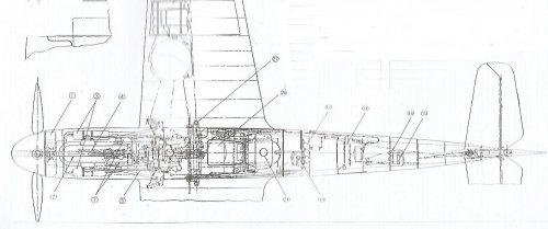
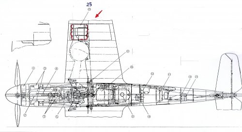
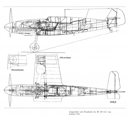
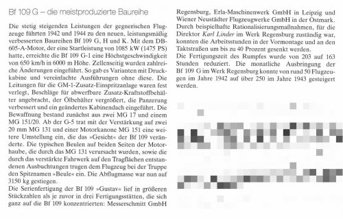
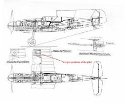
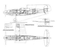
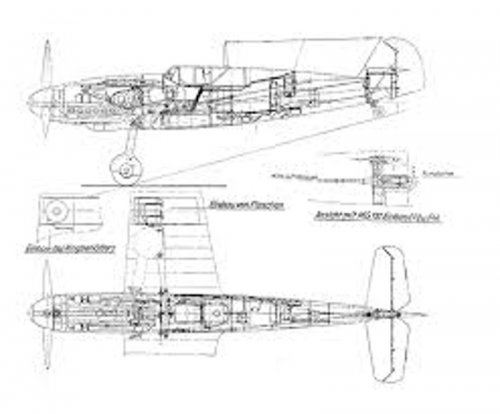
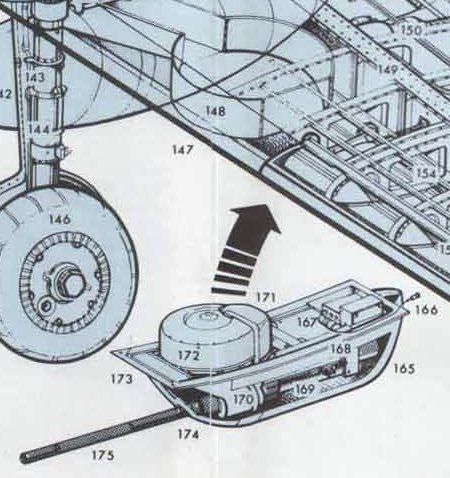
I was asked about those bottle (or cylinders) appearing (really not appearing but I know there are...) on the right wing of this Bf 109G-2 in that squared area immediately next to the landing gear housing, on the right side. The drawing is surely of Japanese origin but I don't knowwhere it came from. Talking about that matters with my sons, we found only cutaways drawings of Bf 109E, F and G-10, all without these four rather large bottles (apparently at least four per wings). Usually bottles are for oxygen, hydraulics, pneumatics or water-methanol injections system.
Could you tell us some hints?
Forgive me for the bad quality of the scan but we are in an emergency.
Thank a lots

Nico
 
Sorry: I forgot the drawing
 

Attachments

  • Bf 109G-2.jpg
    Bf 109G-2.jpg
    153.9 KB · Views: 363
I believe they represent the Oxygen bottles: The oxygen system consists of a cockpit-mounted flow valve with the attached flow monitor, the regulator unit with oxygen hose, and high-pressure lines with pressure gauge, and a set of spherical 2-liter bottles located in the right aircraft wing that contain the oxygen. The bottles are split into three banks of three as a safety measure.

17.gif
 
I'm not at all sure, but I'm more inclined to think those are just structural elements of the wing that look like they depict four bottles close to each other.

In that position there should be the provisions to attach the Rüstsätze. The R6 is the first installation that came into my mind and that's pretty much exactly in that same spot.

The oxygen bottles depicted in the drawing that GTX posted, seems to be roughly at the extremity of the wing, rather than close the landing gear.

Hope someone with better insight than me can help you out.

Regards.
 
that's a BF-109K with GOX in wing
at the BF-109G the GOX tanks went behind the Pilot in Fuselage

source
This Handbook about BF-109K
http://www.avia-it.com/act/profili_daerei/libretti_velivolo/PA_libretti_PDF/Bf-109K4.pdf

and this Cut view of a BF-109G
https://www.upload.ee/image/4124141/109example.jpg
look under #83 Oxygen Cylinders

so what is then that ?
i guess the LUTZ tanks for nitrous oxide injection to boost the engine DB 605A engine.
 
Dear friends:
thank to all of you. Now I can provide a better scan.
As you can see, the four bottles are definitely cylinders, not spherical; moreover, the connections to the fuselage are small gauge (but I don't know what that implies). As you can see from the font of numerals, the drawing is very probably of Japanese origin and, moreover, on the left is a scrap view of the same portion of the wing: that could means that the instalment of the large bottles is an optional kit?
As the tubing seems to reach a device in the cockpit (or near it) we can think to oxygen bottle but why so large? And why this section drawing is the only depicting this solutions?
At any case oxygen remain, with GM 1 injection system for the DB 605A, the best suspcet, but what about a personal interpretation of the author of the drawing or (I invented it on the spot) some sort of temporary pressurisation system as the G-2 version was deprived of it?
Thank you again

Nico
 

Attachments

  • Bf 109G-2 upper section.jpg
    Bf 109G-2 upper section.jpg
    362.2 KB · Views: 282
Hello!

I think I found a source of picture (at least, the one of it)
In German book "Willy Messerschmitt, Pionier der Luftfahrt und des Leichtbaues : eine Biographie." (ISBN: 3763761039 / 3-7637-6103-9): pages 124-125

Hope, this helps!
 

Attachments

  • Bf109G-2_from Willy Messerschmitt book.jpg
    Bf109G-2_from Willy Messerschmitt book.jpg
    840.8 KB · Views: 309
  • Bf109G2.jpg
    Bf109G2.jpg
    363.9 KB · Views: 239
Good news and bad news.

Good: I found the same drawing online and there's definitely a written indication of what that spot is meant to depict.

Bad: the page hosting the drawing is "kaput".
Very bad: I tried to access it using the wayback machine but had no luck. There are no URLs captured for that specific page.
Incredibly bad: I tried to download the preview image shown by google images and it's way to small to discern what's written on it...

I'm adding below the images I've found and the trials I made to scale them up to a readable size.

This is the site URL I was trying to access via the wayback machine: https://web.archive.org/web/*/http://www.angelfire.com/fl5/jg1history/*

And this is the specifc URL of the page where the drawing was once hosted (notice, it says Bf109F details): http://www.angelfire.com/fl5/jg1history/jg1history_crafts/Bf109Fdetail/bf109Fdetail.htm

The writings seems to be in German (so maybe it's an original drawing?), aside from what I suppose is a translation to English (written in red) of the same exact part you're looking for.

Edit:
Silencer1 found a definitely way better image!
Seems to depict an alternative installation of left "einbau des ringbehälters" "installation of pressure vessel" (?) right "einbau von flaschen" "installation of bottles".

So you're definitely right, those are bottles.

Regards.
 

Attachments

  • bf109.jpg
    bf109.jpg
    7.4 KB · Views: 277
  • bf109-1.jpg
    bf109-1.jpg
    6.8 KB · Views: 267
  • bf109-large.jpg
    bf109-large.jpg
    59.6 KB · Views: 114
  • bf109-1large.jpg
    bf109-1large.jpg
    54 KB · Views: 126
CiTrus90 said:
Seems to depict an alternative installation of left "einbau des ringbehälters" "installation of pressure vessel" (?) right "einbau von flaschen" "installation of bottles".

Perhaps thing, drawn left of the wing shows the of cannon MG-151 cartridges container?
There is several versions of factory kits (R- and U-) for fighter filed improvement. And MG-151 installation is one of them.
 

Attachments

  • ringbehälters.jpg
    ringbehälters.jpg
    112.5 KB · Views: 88
Thank you to all of you: you have done a terrific work.
We still lack a definitive word but we could be pretty sure that the drawing depicts an installation of one of the several modification kit.

Nico
 
looking on German text on that image
the system are labeled as

Einbau von Flaschen = installation of tanks
Einbau des Ringbehälters = installation of Ring tanks

from the German Literature i know that the GM-1 (aka HaHa-Gerät)
used eight LUTZ tanks or two ring tanks
 
Found this on this site: http://forums.ubi.com/showthread.php/126106-BF-109-G-2-GM-1-Booster/page4

Note that this does not mean that the equipment was always carried (difference from the E-7/Z) but that it could be fitted if needed. Two kinds of GM-1 devices could be carried either one relying on 8 GM-1 bottles (4 per wing) or two large torric bottle (1 per wing).
The same system was used on the 109G-1 which had the necessary piping installed. But it does not mean it was always carried. Indeed the bottles were removed when not used. Moreover the highly pressurized bottles very not found very practical especially so since it suffered from explosive decompression when hit by bullets. Hence the introduction on the G-5/G-6 of the low pressure system which was serialy mounted on the /U2 aircraft. This system was also retroffited to some earlier G-3, under the designation G-3/U2.

;D

Edit:
Ah, beaten another time! Michel Van posted before me :-[

Still, great we could find the answer, kudos to everyone!

Regards.
 
I hope it can be here

what is it Rüstsatz R VII - Peilrufanlage ???
other Rüstsatz packages I found

thank you
 
Back
Top Bottom