McDonnell Douglas (Boeing) X-36 Tailless UAV

Some articles from Aviation Week from the 90's, on the X-36, a couple from the late Michael Dornheim

X-36 to test agility of tailless design - Michael A. Dornheim


The NASA/McDonnell Douglas X-36 will bring a new look to stealthy fighter designs when it is unveiled in St. Louis on Mar. 19.

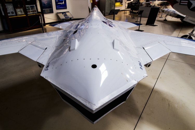
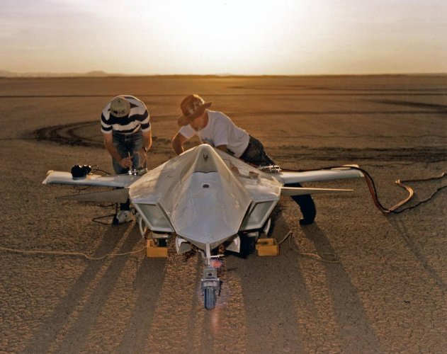
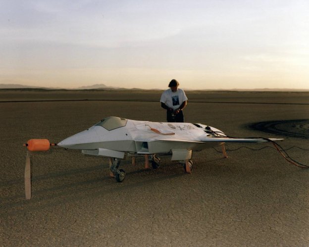
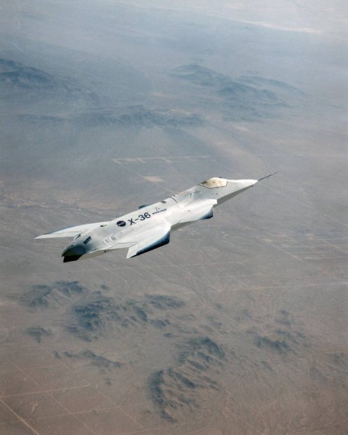
The X-36--a 28% scale drone version of a notional manned aircraft--does not have a vertical or horizontal tail in order to achieve low radar cross section (RCS). This configuration has already been used in the USAF/Northrop B-2 bomber, but with maneuverability that is too low for a fighter. The B-2 has a 65-deg. bank restriction, while the X-36 full-scale goal is to outmaneuver an F/A-18 fighter.

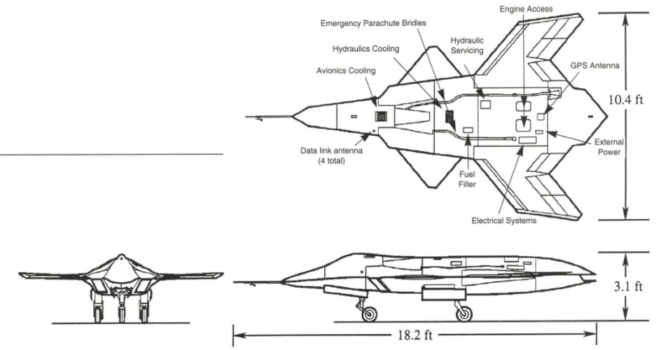
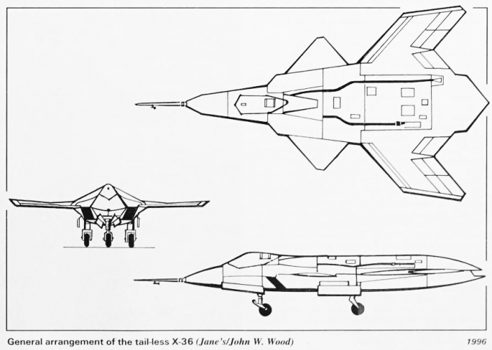
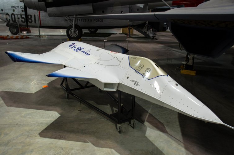
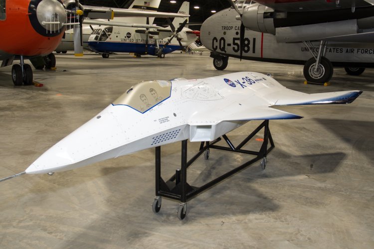
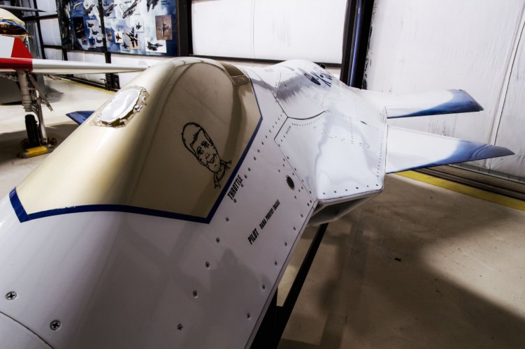
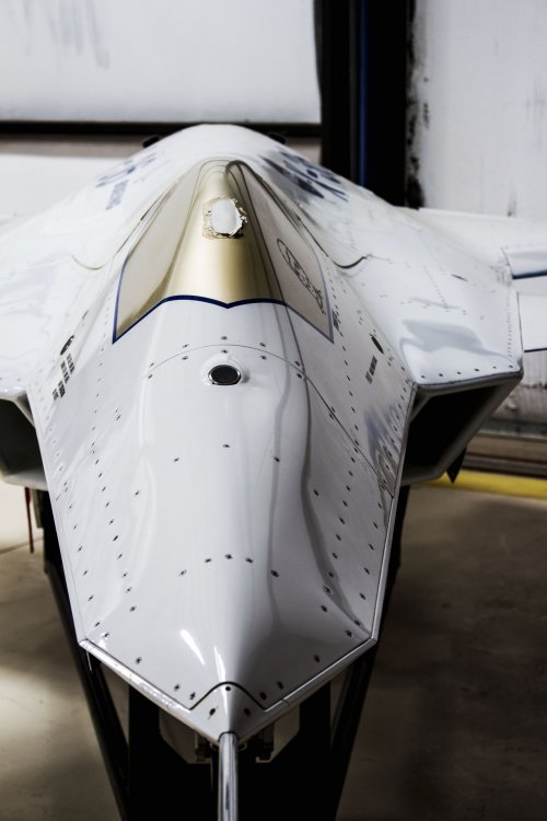
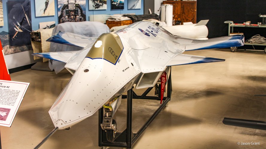
The purpose of the X-36 is to prove to the fighter community that the tailless configuration is viable, and to validate the design techniques used by NASA and McDonnell Douglas, which have been tested in wind tunnels at 3-15% of full scale. The dynamically scaled X-36 is big enough to give meaningful results, yet small enough for low cost, Larry D. Birckelbaw, NASA Ames Research Center X-36 program manager, said. It is 18.4 ft. long and has a 10.4-ft. span, and is powered by a 700-lbf. Williams F112 turbofan engine (AW&ST Feb. 26, p. 17). Fully fueled weight is about 1,300 lb. The shape and some other details are being kept secret until the rollout. The X-36 does have a distinct fuselage with a cockpit area, and edges of the planform are aligned to keep radar reflections away from vulnerable aspect angles.

YAW CONTROL WILL BE by split-aileron drag rudders that are a little different from the B-2. But an aft center of gravity mildly destabilizes the X-36, making it more responsive. The aircraft is also mildly aerodynamically unstable in pitch. Software keeps it under control.

Besides low RCS, the tailless configuration has small benefits in drag and weight--roughly 10% less drag and 5% less weight, Birckelbaw estimated. "A lot of the motivation is RCS," he said. "A tail has very significant directional control and pitch control power at lower angles of attack. One would prefer to keep the tail."

The X-36 also has thrust vectoring, some thing the B-2 does not have, but the vectoring is not necessary. "The X-36 has high agility without vectoring," Birckelbaw said. "The vectoring enhances agility and makes the aircraft more efficient in cruise," for example, by eliminating the need to open the split ailerons.

The two-axis stealthy vectoring system was designed by Ames and is one of the novel Features of the aircraft. Current low RCS nozzles, as exemplified by the Lockheed F-22 design, have upper and lower flops that only vector in the pitch axis. The side plates are fixed. The flaps have a diamond-shaped trailing edge aligned with major airframe planform features to reduce tail-aspect radar reflections. Current two-axis vectoring nozzles are round, with much higher RCS. The novelty of the X-36 nozzle would appear to be in having two-axis vectoring while maintaining low RCS.

Nozzle failure should not be a problem, Birckelbaw said. The aircraft has sufficient aerodynamic control power to have good "level one" flying qualities with the nozzle locked in any vectoring position, he said. The inlets-engine-nozzle combination has been tested at Lewis Research Center.


The X-36 is being built by McDonnell Douglas Aerospace's "Phantom Works" in St. Louis using rapid prototyping techniques. Frame members are built largely out of aluminum, while the skins are low-temperature-cure graphite composite. Some titanium is used in the nozzle. The aircraft is not intended for RCS tests and does not incorporate special radar treatments. Model RCS tests have already been conducted at NASA Langley Research Center and other radar ranges.

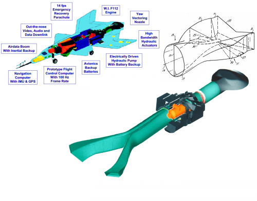
THE AIRCRAFT WILL TAKE OFF and land on retractable wheeled landing gear, and there is a recovery parachute for emergency use. To reduce cost, aircraft systems are generally single-string with no redundancy; instead, two identical X-36s are being built. Controls are hydraulically actuated, with power from a single electric pump with battery backup. There is only one data link and attitude reference system.

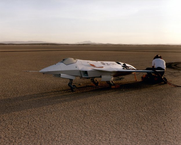
The flight test program is to take place at NASA's Dryden Research Center, Edwards AFB, Calif. First flight is expected around July, and a 25-flight program over six months is planned to demonstrate the tailless configuration and quantify its capability. The angle of attack (AOA) will be limited to the 30-40-deg. point of maximum lift, Birckelbaw said.

McDonnell Douglas will bring a ground control station to Dryden housing the ground "cockpit" and data collection equipment. The X-36 is to be manually piloted to avoid the complex development of fully autonmous operation, and backup autonomous modes are mainly for data link loss and other emergencies. An autopilot can fly between GPS waypoints, and basic aircraft parameters will be measured by automatically pulsing controls. Pilots will receive special training because the dynamic scaling will make the X-36 maneuver up to twice as rapidly as a full-scale aircraft. A camera in the X-36 cockpit position will provide pilot video. A synthesized head-up display also will be used.

Maximum speed for this first phase of flight test is 160 kt., which is the structural limit should the aircraft pitch out of control to 90-deg. AOA. The X-36 is designed For 240 kt. equivalent airspeed, and there is enough thrust for 350-400 kt. The full-scale aircraft is designed to have supersonic speeds, but the X-36 is only for subsonic tests.

A second program phase would extend to beyond stall AOA and cost several million dollars over a 2-3-year period. The powered X-36 would first be tested in Ames' 40 X 80-Ft. wind tunnel to measure controllability. This phase has not been Funded yet, and the value of post-stall maneuvering is open to debate, particularly in light of high off-boresight-angle missiles that may be able to accomplish the same effect (AW&ST Oct. 16, 1995, p. 36).

Ames' military technology branch, now headed by Birckelbaw, has been developing stealthy Fighter concepts since the mid-1980s. The branch examined what technologies were required to realize these concepts, and pushed development of those technologies. They were examined not in isolation, but in how they affected all aspects of the design.

Several contractors conducted studies, and the relationship concentrated on McDonnell Douglas after 1989 because it had better success with key breakthroughs, Birckelbaw said. Tens of millions of dollars were spent to secretly develop the tailless design from 1989 to February, 1994, when the company and NASA decided on the size of an X-vehicle to validate their concepts. The subscale demonstrator was McDonnell Douglas' idea.

THE THREE-YEAR EFFORT to build the X-36 From then until the end of Flight test is expected to cost $17 million, with $10 million provided by McDonnell Douglas. "The X-36 is also showing how to do business differently, with contractor teaming and bringing the aircraft to test quickly," Birckelbaw said.

The X-36 is being tested openly, instead of being hidden at a remote site like the base at Groom Lake, Nev. "Times have changed," he explained. "The F-117 and B-2 have shown the radical shapes. Low RCS shapes are now okay to show to the public. The X-36 doesn't have any low-observable materials or other classified features. And a very strong port of our decision is that it's less expensive. Remote sites are hard to find and costly, and we couldn't justify it."

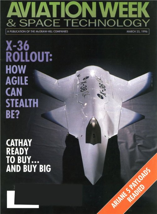
McDonnell Douglas Rolls Out X-36: Some features of stealthy designs can hurt agility. The X-36 may show how to overcome them - Michael A. Dornheim


Last week's X-36 rollout at the McDonnell Douglas Aerospace factory here revealed a design with a variety of control surfaces indicating its role of testing whether stealthy supersonic aircraft can also be agile.

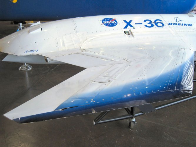
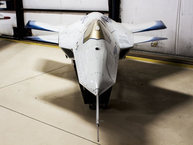
The drone, a 28% scale version of a notional manned fighter, has two large canards, 10 trailing-edge surfaces and leading-edge flaps. It also has yaw-axis thrust vectoring and is mildly unstable in pitch and yaw.

The 1,270-lb. aircraft, a joint NASA/McDonnell Douglas project, is to start a 25-sortie, six-month flight test program at the Dryden Flight Research Center this summer. The flights will measure the reliability of design techniques, which have been tested so far with 3-15% scale wind tunnel models. X-36 development was led by Ames Research Center, and two aircraft are being built.

The X-36 has stealthy and supersonic features that tend to hurt agility, and designers believe that clever aerodynamics and flight control laws can overcome these problems. Agility-penalizing features include:

-- The lack of a vertical tail for low radar cross section (RCS), which makes it difficult to produce yaw forces. Instead, they are provided by wingtip drag rudders and thrust vectoring.

-- Chined fuselage for low RCS. This shape can create so much forebody vortex lift at high angle of attack (AOA) that it is hard to put the nose back down. The canards are used to overpower the forebody lift.

-- Sharp leading edges for low RCS and low supersonic drag. They make it difficult to efficiently produce high lift, but leading edge flaps and biasing other control surfaces may compensate.

-- A thin wing for low supersonic drag, which makes it difficult to install powerful actuators for large, rapid-rate controls. X-36 engineers reconfigured actuators for a lower profile. The 7% wing thickness is not much more than the 5-6% typical of a supersonic design, David J. Manley, McDonnell Douglas X-36 program manager, said.

The X-36 has a cranked-arrow wing and large canards, though it is officially ``tailless.'' The canards are mainly to provide nose-down moment, and help destabilize the aircraft in pitch.

The planform lines are aligned to keep major radar reflections along relatively benign aspects, and the chined fuselage bounces waves up or down away from most radar observers. The thin, broad ``platypus'' exhaust nozzle limits viewing up the tailpipe to a narrow range of angles, as well as spreading the plume for low infrared signature. The nozzle interior is likely designed to minimize retroreflection, although special radar-absorbing materials were not used in the X-36.

Because of the drone's 28% scale, actual radar-absorbing materials would not provide meaningful data.

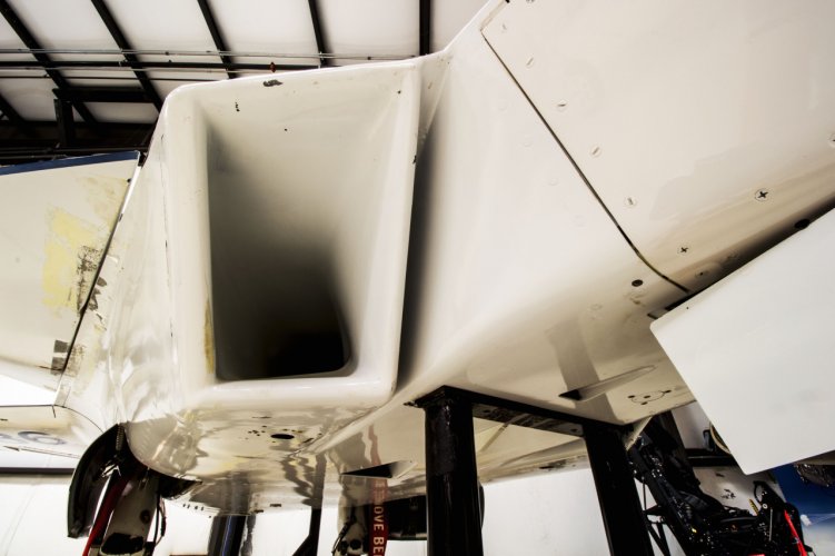
The scarfed F/A-18E/F-style inlets are a gesture toward low observability, but as implemented with a large lip radius for low airflow distortion, they would not be too effective. The Y-duct to the center engine blocks the fan blades from head-on radar viewing, but they can be partly seen from a moderate side angle down one duct.

The aircraft's aft center of gravity makes it mildly unstable in pitch and yaw for increased agility. Software keeps it under control.

The wings have 2.5-deg. washout twist to prevent tip stall and compensate for canard downwash along the inner span. The wing and canard leading edges have a sharp radius of roughly 0.005 in. for low RCS and low supersonic drag. This, along with the sweep angle, means that high-AOA flight will be dominated by vortex lift, which can create high drag.

Each wing has four control surfaces. There are two split ailerons at the wingtip with independent upper and lower surfaces that can act as drag rudders and ailerons at the same time. The upper surface can move 60 deg. up and 30 deg. down, while the lower surface moves +30 deg., -60 deg., giving +/- 30 deg. of solid aileron motion, and twice that as a split aileron. They have a common hinge line at the lower wing surface so the tips don't rub when they move as a solid aileron. A flexible rub strip keeps the upper surface sealed to the wing as it moves. The split ailerons are broken into inboard and outboard surfaces to keep actuator loads acceptable and for redundancy, and the surfaces move in unison.

The inboard solid surface is an elevon used for roll and pitch, and it moves 30 deg. To increase maximum lift for takeoff and landing, all the trailing-edge surfaces bias down while the canard biases up to maintain trim and add lift.

The leading-edge flap is the fourth control and is programmed to deflect as much as 40 deg. down with increasing angle of attack and AOA rate, to prevent yaw-roll dihedral coupling from becoming uncontrollable at high AOA. The left and right sides are not mechanically connected, but software moves them in unison.

The controls move at rates similar to advanced fighters like the F-22. Actual model rates are about twice as fast owing to dynamic scaling. In practice, the leading edge flap moves slower than the other surfaces.

The 7% thin wing had little room for actuators, so Moog Inc. removed the control valves from its linear actuator bodies and relocated them to an inboard manifold. A linear variable differential transformer on the actuator senses position. The 3,000-psi. actuators produce 1,200-lbf. force over a 1.5-in. stroke and are about 6 in. long.

The canards are not mechanically connected but only move in unison for pitch control. Motion is 10 deg. nose up and 80 deg. nose down. Hydraulic power for all the controls comes from an Abex 3,000-psi., 7.4-gpm. electric pump with a small accumulator. The aircraft electrical system is powered by a 28-v, 200-amp Lucas starter/generator, and batteries provide about 5 min. of backup power.

Engineers originally planned to place flight control software in a Honeywell integrated flight management unit (IFMU) that contains the laser gyro inertial reference and GPS navigation, but the software grew beyond an easy fit into the IFMU. It now resides in a McDonnell Douglas computer originally designed for the actuator servo loop and air data sensor processing.

This computer uses seven Texas Instruments C (superscript) 3 1 digital signal processor chips for a total speed of 117 million instructions per second. It now processes the flight control laws at 100 Hz. while controlling the actuators at 1,000 Hz., as well as retaining its other original functions. Controlling a 28% subscale drone requires high computational rates because dynamic scaling makes things happen about twice as fast.

For simplicity, the X-36 will be manually piloted from a cockpit station in a control and data collection van. The pilot can look at a television screen showing cockpit-viewpoint video overlaid with head-up display symbology. The aircraft has an autopilot that can fly between waypoints.

With no force on the stick, the pitch control law holds a constant AOA, and AOA is proportional to stick force. This natural-handling scheme is relatively simple to use in the drone and may not represent manned aircraft control laws. AOA is limited to the 35-deg. point of maximum lift for this phase of flight tests, as wind tunnel spin tests have not been done. Roll rate is proportional to stick force and at high AOA the roll is around the velocity vector. Rudder pedals command sideslip at low AOA, blending to roll at high AOA.

Three gain settings can be used. Low and medium gain are used for takeoff, landing and most cruise operations. High gain gives very rapid response, with rates twice that of a full-scale fighter. An automatic routine can measure the response to individual control surfaces.

The thrust-vectoring system is yaw-only, not both yaw and pitch as previously reported, and is a McDonnell Douglas concept (AW&ST Mar. 4, p. 20). The Williams F112 turbofan cruise missile engine has a 0.85 bypass ratio to provide some cool air to the platypus nozzle, and the team added an eight-lobe daisy mixer in the engine exhaust to ensure uniform 800-900F temperatures, avoiding the risk of hot streaks in coaxial fan/core flow. The engine attaches with a band clamp to titanium ductwork to transition to the rectangular nozzle cross section. Fuselage skins around the exhaust are aluminum instead of graphite-epoxy to take temperatures up to 200F.

The vectoring is not necessary. Aerodynamic control power is great enough to overcome a hardover vectoring position. But vectoring can improve performance by allowing the drag rudders to remain closed for lower RCS and drag.

Engine inlets for the drone were designed to be low-risk, according to Dave Zilz, McDonnell Douglas propulsion and thermodynamic team leader. They have large lip radius and a contracting cross section to provide good airflow to the engine face. The penalty is excessive spillage drag from the oversized inlets. Maximum engine airflow is 14.6 lb./sec.

About $29-30 million will have been spent on X-36 from the start of development to the end of the first phase of flight test in early 1997. Broken down, Ames spent $12-13 million from 1989 through the start of detail design in February, 1994, with McDonnell Douglas under contract. From then until early 1997 Ames will spend another $7 million while McDonnell Douglas is providing $10 million for the detail design and construction of the two drones. The cruise missile engines were provided by the government.

THE OUTER MOLD LINES were frozen in June, 1994, and fabrication of the drones started in June, 1995. Structure of the second X-36 is now being assembled. The aircraft has a machined aluminum frame covered with carbon-epoxy fuselage and wing skins.

The X-36 was praised at the Mar. 19 rollout for meeting NASA's goals of ``faster, better, cheaper,'' by Robert Whitehead, NASA associate administrator for aeronautics. He said it was taking about one-fifth the cost and one-third the time of a conventional manned X-plane.

A key to this was avoiding redundant systems, Larry D. Birckelbaw, the Ames X-36 program manager, said. ``NASA Dryden told us their experience with Himat was that redundancy resulted in gold-plating,'' he said. Himat was a 3,000-lb. single-engine drone air-launched from a B-52 to test highly maneuverable fighter technologies.

``Himat had a lot of redundancy,'' Manley said. ``I estimate X-36 will be about one-fourth their cost.''

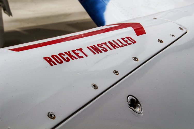
Most of the X-36 is single-string, including the radio link, flight control computer, air data and inertial reference systems. Loss of radio signal activates simple autonomous ``fly-home'' modes, and a Pioneer parachute aft of the cockpit can be deployed for an emergency landing. It is bridled to land the aircraft in a flat attitude at the 14-fps. landing-gear sink rate limit.

The disadvantage of the X-36 single-string approach is possible higher risk, but this is addressed by building two of the aircraft. The X-36 is also freed of relying on the B-52 by being able to take off and land by itself.

Third X-36 Test Series To Explore Low-Speed Agility


The third series of NASA/Boeing X-36 flight tests were scheduled to begin late last week, aimed at evaluating agility at low speeds, where the remotely piloted aircraft's stability and performance will depend heavily on thrust vectoring.
A fourth phase will expand the flight envelope to its design limit speed and explore stability margins in that area. Having no vertical tail, the X-36 uses split drag rudders and thrust vectoring for directional stability and control.

Another 6-10 flights are planned in the program.

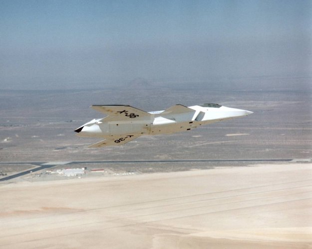
First flight of the X-36 was made May 17 (AW&ST May 26, p. 21). By early September, the 28%-scale, tailless research aircraft had completed 22 flights (10.9 hr.), reached 4.8g, 40 deg. angle-of-attack (AOA) and 177 KEAS (knots estimated airspeed), and achieved Level 1 handling qualities on the Cooper-Harper pilot's rating scale.

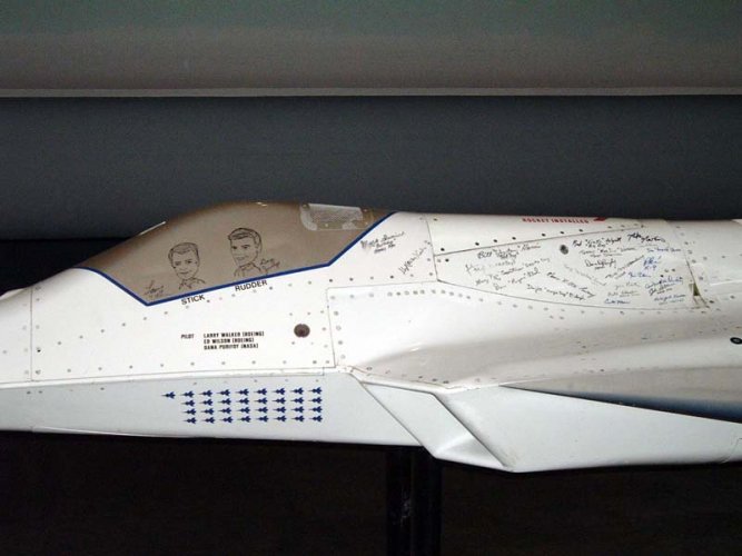
Initial agility tests--conducted with thrust vectoring on and off--produced roll rates that exceeded goals ``by an appreciable margin,'' according to Laurence A. Walker, chief experimental test pilot for Boeing/St. Louis flight operations. Second-phase evaluations of accelerated-g, bank-to-bank rolls (or rolling pullouts) confirmed that ``roll rates were spectacular,'' he said. ``These rates exceeded those of any aircraft I've flown by a dramatic margin.'' Actual speeds, aerodynamic performance and control-response data are classified.

BETWEEN THE FIRST AND SECOND test phases, revisions to flight control system laws and stability margins improved X-36 handling qualities significantly, Walker reported to the Society of Experimental Test Pilots' 41st annual symposium here. Prior to the software changes, several deficiencies had prompted less-than-optimum handling qualities ratings from the pilot. ``A bit of pitch bobble'' that made capturing a desired pitch attitude difficult, and ``an unusual spiral divergence, which tended to steepen all bank angles and required some lateral stick deflection toward wings-level in turns'' required ``considerable pilot attention,'' he said.

Overall, though, the X-36 program is meeting all its objectives, and the test vehicle has proven to be quite reliable. In Phase 1, 14 flights were completed in 35 calendar days; seven were flown in an eight-working-day period.

Walker said the Boeing/NASA X-36 team found that cockpit design and a rigorous, safety-based process of planning, practice and test conduct are critical elements of a successful research RPV program. A well-designed ground-based cockpit ``was especially important . . .because the pilot is missing kinematic cues he'd have in a full-size airplane,'' he noted. Cues typically absent when flying an RPV include peripheral vision, sounds and accelerations on one's body.

The pilot's station at NASA's Dryden Flight Research Center features ``out-the-nose'' video with a head-up display (HUD) overlay and symbology emulating that of an F/A-18 or F-15E fighter. A large horizontal situation display shows boundaries of the X-36's operating area around Edwards AFB, Calif., as well as runway layouts and the status of a data link that ties the pilot to his subscale aircraft. The throttle and stick came from the Navy's aborted A-12 stealth attack fighter program.

A microphone in the X-36 ``cockpit'' area provides audio cues that help the pilot establish engine power settings and detect potential anomalies that might not be captured by instrumentation. For example, downlinked audio indicated engine ``pop-stalls'' were occurring at high power settings, enabling rapid throttle reductions before they caused any damage, Walker said. A ``screech'' at high power settings has yet to be identified, but may be a panel vibrating in the engine inlet.

Additional symbology presented on the HUD provides cues that might not be necessary in a manned aircraft, where the pilot can feel varying forces on his body. The display features a standard pitch ladder, steering points, navigational bearing and distance to the next steerpoint, and digital readouts of airspeed, altitude, AOA and normal acceleration. An analog ``specific power'' indicator adjacent to the airspeed data box ``was extremely valuable'' as an aid to quickly setting the throttle for a ``trim'' point prior to starting a test maneuver, Walker said. An analog vertical line down the left center of the display presented AOA on one side and normal acceleration (in g's) on the other.

When landing, three small vertical lines appear under the HUD's flight path marker, indicating landing gear are down and locked. Small circles attached to those lines are displayed when the wheels touch down and spin up during rollout.

A special autopilot feature was used to initiate preprogrammed real-time stability margin and parameter identification maneuvers. These provided repeatable control ``sweeps,'' and single- and double-motion flight control inputs (called singlets and doublets). Automated maneuvers were activated when the pilot squeezed a trigger on his control stick, and ``greatly facilitated envelope expansion,'' Walker said.

THE MOST SIGNIFICANT PROBLEM encountered during the test program, so far, was loss of a control data link on the second flight. At 12,000-ft. altitude, approximately 10 mi. from the control station, video and telemetry signals became weak and displays started breaking up. A ``break-X'' appeared, indicating the X-36 had switched to its preprogrammed autonomous operation mode.

``A new $20-million aircraft was suddenly on its own, and all I had was a frozen display with a big `X','' Walker said. ``I felt helpless. . . .It was almost like ejecting on a dark night and not knowing where your airplane went.''

In this mode, the aircraft is mechanized to fly toward the nearest steering point, then back to an autonomous orbit position over the Rogers Lakebed. Intermittent data link operation complicated the recovery, but well-rehearsed procedures reestablished control, enabling a safe landing. Postflight analyses showed that a low-noise amplifier was not sensitive enough at midrange temperatures to maintain a strong link. It had passed qualification tests at both high and low temperatures.

The X-36's agility and rapid response underscored the value of having a trained test pilot who was familiar with fighter maneuvers at the controls during a research program. Problems and emergencies demonstrated that a human ``in-the-loop'' provided invaluable flexibility that would not have been possible with a totally autonomous system, such as those being developed for some operational unmanned aircraft.
 
Thanks. I always shrug at the mention "Boeing X-36", considering the fact that the aircraft was developed and tested entirely while under McDonnell Douglas. Boeing merely purchased the company and stuck their logo onto it. At least "McDonnell Douglas (now Boeing) X-36" would be more respectful of the history and heritage. They've appropriated everything that was done by the companies they've acquired as if they were parts of their own history... I know most industry giants have a tendancy to do that, but Boeing has gone a step further in doing that; McDonnell, Douglas, North American, Curtiss-Wright, Vertol... These venerable and important entities in the history of aviation deserve more recognition than being footnotes in Boeing's megalomaniac rewriting of its own history.

EDIT: just noticed the change in the topic's title, @overscan (PaulMM) . Great minds! ;)
 
Hi folks,
this video is one year old, but the title has been recently changed.
Paul Stewart said:
Has the Boeing F-47 been on display for years? The Boeing X-36!
#airplane
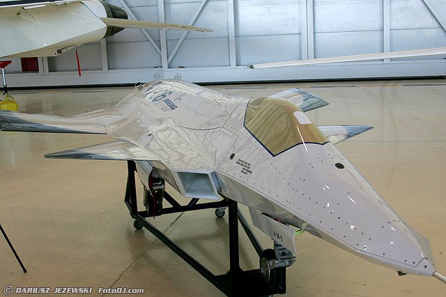
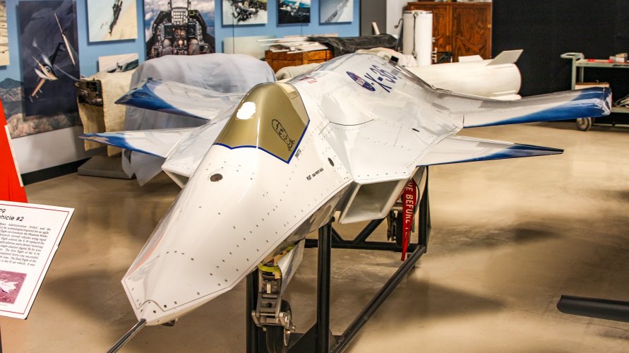
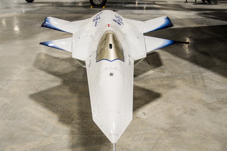
Boeing F-47 F47 stealth fighter preview?? .Detailed our of the McDonnell / Boeing NASA X-36 Tailless Fighter Agility Research Aircraft on display at the National Museum of the United States Air Force in Dayton, OHIO. A hint of the American Next Generation Air Dominance (NGAD) program? [...]
Video:
View: https://youtu.be/icuuMaf7l44?si=VqNW2FfeopSBoRY4

Link:
Code:
https://youtu.be/icuuMaf7l44?si=VqNW2FfeopSBoRY4
 
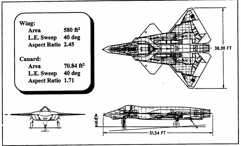
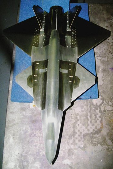
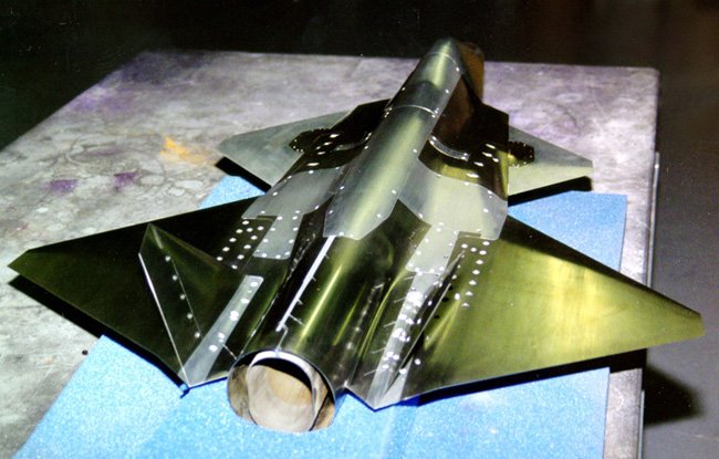
When the F-47 is finally revealed in its entirety I won't be surprised at all if it turns out to be basically a full-scale piloted X-36 type airframe with two engines.
 
When the F-47 is finally revealed in its entirety I won't be surprised at all if it turns out to be basically a full-scale piloted X-36 type airframe with two engines.
Something like this?
 

Attachments

  • y7pSJ7-UserView-0.jpg
    y7pSJ7-UserView-0.jpg
    81.5 KB · Views: 130
IMG_5958.jpeg

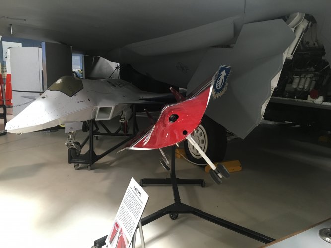
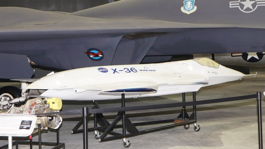
The red aircraft is LoFlyte, the aircraft the X-36 is under is a YF-22. There is also a Tacit Rainbow hiding under there.
 
Last edited:
Regarding the X-36, I have some images that might be of interest.


Regards,
 

Attachments

  • X-36_at_the_National_Museum_of_the_USAF_right_front_view.jpg
    X-36_at_the_National_Museum_of_the_USAF_right_front_view.jpg
    332 KB · Views: 28
  • X-36_at_the_National_Museum_of_the_USAF_left_front_view.jpg
    X-36_at_the_National_Museum_of_the_USAF_left_front_view.jpg
    1.2 MB · Views: 29
  • X-36%20U%20Wright.jpg
    X-36%20U%20Wright.jpg
    60.1 KB · Views: 28
  • x-362.jpg
    x-362.jpg
    218.4 KB · Views: 32
  • tumblr_nehaebDvcI1ttka3go6_1280.jpg
    tumblr_nehaebDvcI1ttka3go6_1280.jpg
    242 KB · Views: 31
  • tumblr_nehaebDvcI1ttka3go5_1280.jpg
    tumblr_nehaebDvcI1ttka3go5_1280.jpg
    240.4 KB · Views: 28
  • tumblr_nehaebDvcI1ttka3go4_1280.jpg
    tumblr_nehaebDvcI1ttka3go4_1280.jpg
    202.7 KB · Views: 23
  • tumblr_nehaebDvcI1ttka3go3_1280.jpg
    tumblr_nehaebDvcI1ttka3go3_1280.jpg
    390.6 KB · Views: 28
  • tumblr_nehaebDvcI1ttka3go2_1280.jpg
    tumblr_nehaebDvcI1ttka3go2_1280.jpg
    219.3 KB · Views: 27
  • tumblr_nehaebDvcI1ttka3go1_1280.jpg
    tumblr_nehaebDvcI1ttka3go1_1280.jpg
    253.4 KB · Views: 24
  • 40501508221_dcc8e85007_o.jpg
    40501508221_dcc8e85007_o.jpg
    1.2 MB · Views: 27
  • 354565main_EC97-44064-11_full.jpg
    354565main_EC97-44064-11_full.jpg
    858.5 KB · Views: 26
  • 354577main_EC97-44064-12_full.jpg
    354577main_EC97-44064-12_full.jpg
    100.4 KB · Views: 25
  • 354613main_EC97-44064-6_full.jpg
    354613main_EC97-44064-6_full.jpg
    84.3 KB · Views: 25
  • DK22_201.jpg
    DK22_201.jpg
    92.1 KB · Views: 16
  • 354661main_EC97-44294-23_full.jpg
    354661main_EC97-44294-23_full.jpg
    96.6 KB · Views: 25
  • 354685main_EC97-44294-6_full.jpg
    354685main_EC97-44294-6_full.jpg
    56.7 KB · Views: 25
  • 5961595085_f6b8e4e747_o.jpg
    5961595085_f6b8e4e747_o.jpg
    2.5 MB · Views: 18
  • 5961595085_f6b8e4e747_o.jpg
    5961595085_f6b8e4e747_o.jpg
    608.4 KB · Views: 24
  • X-36_head-on_view_at_the_National_Museum_of_the_USAF.jpg
    X-36_head-on_view_at_the_National_Museum_of_the_USAF.jpg
    1.1 MB · Views: 36
Last edited by a moderator:
Back
Top Bottom