Junkers Projects and Prototypes until 1918

hesham

ACCESS: USAP
Senior Member
Joined
26 May 2006
Messages
32,704
Reaction score
11,976
Hi,


http://translate.google.com/translate?sl=de&tl=en&js=n&prev=_t&hl=ar&ie=UTF-8&eotf=1&u=http%3A%2F%2Fwww.ju-f13.de%2Findex.html
 

Attachments

  • All Metal.jpg
    All Metal.jpg
    52.2 KB · Views: 222
  • All Metal 2.jpg
    All Metal 2.jpg
    117.2 KB · Views: 239
  • All Metal 3.jpg
    All Metal 3.jpg
    58.4 KB · Views: 226
  • JG.1.jpg
    JG.1.jpg
    39.7 KB · Views: 245
  • Wooden Models.jpg
    Wooden Models.jpg
    36.6 KB · Views: 240
Interesting find, Hesham, especially the JG.1, the construction of it was actually started, until the built
components had to be destroyed on order of the allied control comission.
And thanks for pointing us to that site, which really gives a good overview not only for the F 13, but also
over the early history of the Junkers company.
 
Hi,


various Junkers wing shapes of WW1;


http://alternathistory.org.ua/superbombardirovshchik-kaizera-vilgelma
 

Attachments

  • Junkers C.JPG
    Junkers C.JPG
    59.2 KB · Views: 70
  • Junkers B.JPG
    Junkers B.JPG
    38.9 KB · Views: 52
  • Junkers A.JPG
    Junkers A.JPG
    26.9 KB · Views: 583
Hi,


here is the J.6 fighter project 3-view,was there any drawing to J.12 fighter
derivative ?.


http://flyingmachines.ru/Site2/Crafts/Craft29035.htm
 

Attachments

  • J.6.jpg
    J.6.jpg
    12.7 KB · Views: 202
As requested by Wurger, here are some more details from Gunter Schmitt's book on Junkers project types:

Junkers Project 1 - Junkers J3 - first light metal aircraft

( see also http://hugojunkers.pytalhost.com/ju_j3_a1.htm )

Design was under the auspices of Dr Mader who was chief engineer at Junkers. Although production was started, it was never completed. The J3 was a single-seat low wing monoplane which pioneered the use duralumin corrugated thin sheet during testing of parts.

Work was stopped because of the excessive expense of the technical research and the lack of commercial interest. Work shifted onto the J4 design instead.

Wing Span: 11.45 m
Length: 6.67 m
Height: 3.1 m
Engine: 14 cylinder Oberursel U III (113.9 kW / 155 hp))

------------------------------------------------------------------------------

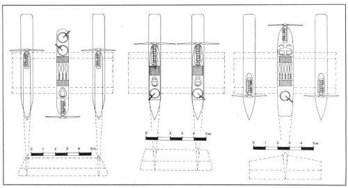
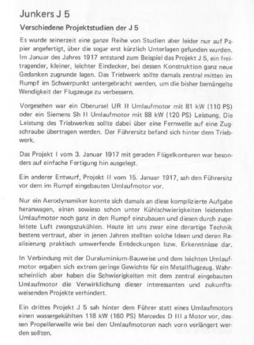
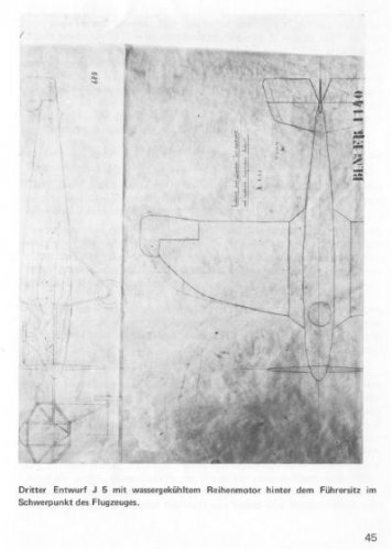
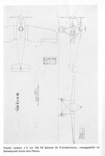
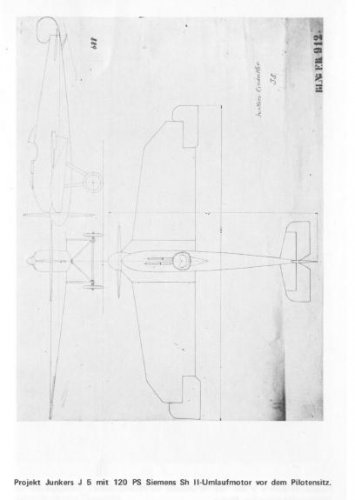
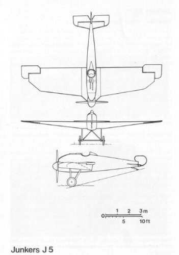
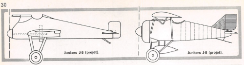
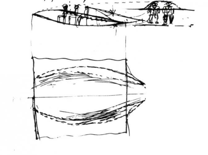
Junkers Project 2 - Junkers J5 - small light , low-wing cantilever monoplane in three planned versions designed but never built .

( See also http://hugojunkers.pytalhost.com/ju_j5_a1.htm )

In early 1917 work started a study into a small, low-wing cantilever monoplane. Three versions were planned each with differing wings forms and control services.

For the first variant, the powerplant was to be installed in the fuselage forward of the pilot being fixed to the propeller by a connecting rod.

In the second and third versions, the engine was behind the pilot with a lengthened propeller shaft running through the fuselage. In this version, the wing contours were rounded

J5 (version 1)
Drawing Date: 3rd January 1917
Engine: Oberursel UR II (81 kW / 110 hp) rotary engine or Siemens Sh II (88.2 kW / 120 hp) rotary engine
Wing Span: 11.8 m
Length: 6.75 m
Height: 2.7 m
Wing Area: 12.00 sq m

J5 (version 2)
Drawing Date: 18th January 1917
Engine: Siemens Sh II (88.2kW / 120 hp) rotary engine
Wing Span: 11.8 m
Length: 8.0 m
Height: 2.8 m
Wing Area: 20.00 sq m

J5 (version 3)
Engine: Mercedes D IIIa (117.6 kW / 160 hp) water-cooled rotary engine
No data for this third option.


------------------------------------------------------------------------------


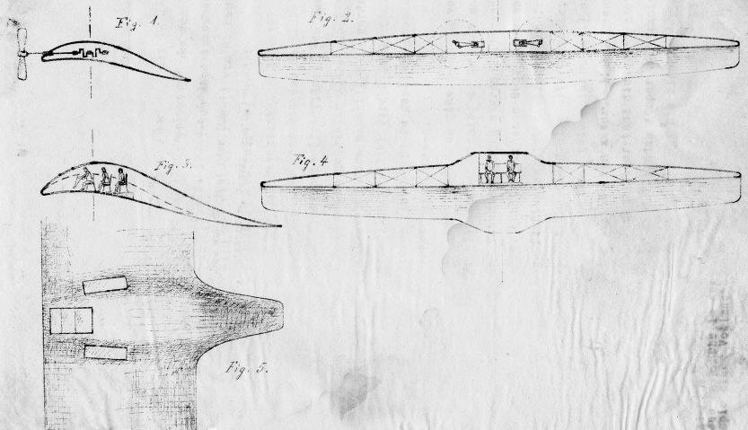
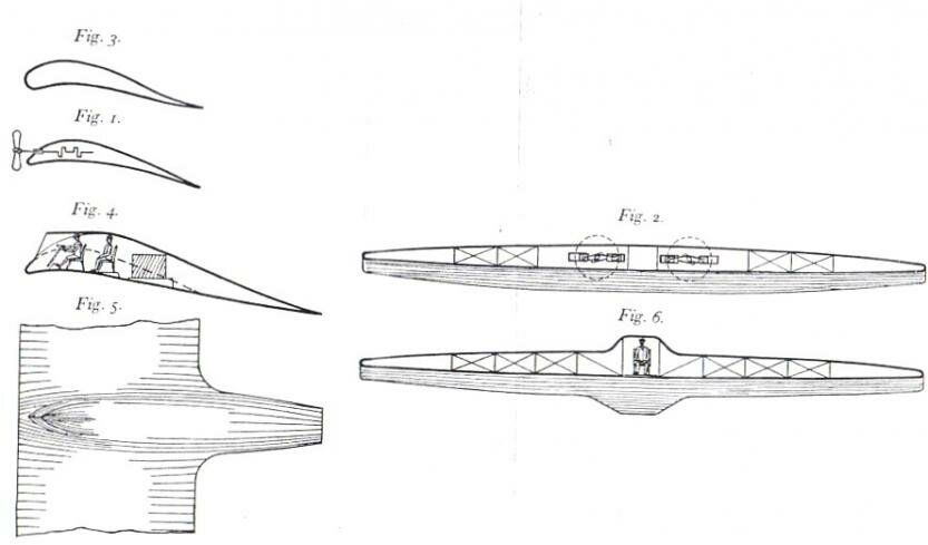
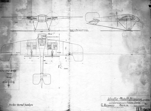
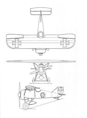
Junkers Project 3 - Junkers J6 - high-wing cantilever monoplane from August 1917. At the wars end, the prototype was half-completed at Dessau.

( See also http://hugojunkers.pytalhost.com/ju_j12_a1.htm )

Design started in August 1917 on this very small all-metal high-wing parasol monoplane. Its small size compromised its manoeuvrability. The engine was found to be far too heavy when located behind the pilot.

The high elevator and fin was an attempt to improve handling. The aircraft was fitted with a 2.8 m diameter airscrew thanks to a high undercarriage. A streamline fuel tank was located in the slender fuselage. When the armistice was signed the prototype was 50% complete in the Junkers workshop in Dessau.

Engine: Siemens Sh III (117.6 kW / 160 hp) engine
Wing Span: 8.0 m
Length: 5.6 m
Height: 2.62 m
Wing Area: 12.00 sq m
Maximum Speed: 190 km/h

------------------------------------------------------------------------------


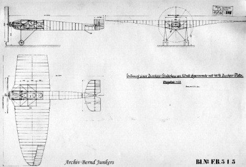
Junkers Project 4 - Junkers R1 - four engine giant monoplane heavy bomber project in two versions, both low-wing.

Junkers Project 5 - Junkers R2 - twin engine giant monoplane heavy bomber project.

Junkers Project 6 - Junkers R3 - four engine giant flying boat project.

( See also http://www.secretprojects.co.uk/forum/index.php/topic,3253.msg177951.html#msg177951 )


------------------------------------------------------------------------------


Source:

Hugo Junkers and his Aircraft (Gunter Schmitt) Transpress (GDR) 1988 ISBN 3344003038
 
Great Cy-27! Keep on pumping more Junkers projects :) . I can`t wait for the 1930`s.
 
Hi,


a strange Junkers aircraft was in a patent of 1910,Luftfahrt 2/1980.
 

Attachments

  • Junkers Patent 1910.JPG
    Junkers Patent 1910.JPG
    68.7 KB · Views: 61
  • 2.JPG
    2.JPG
    69 KB · Views: 61
This strange aircraft is also present in Hugo Junkers' US Patent n° 1,114,364 filed in January 1911 and in which are shown both his "Flying wing" concept and his "Lifting fuselage" concept (i.e. years before De Monge & Burnelli's ones :) ).

http://www.google.com/patents/US1114364
 

Attachments

  • 2014-03-11_151406.jpg
    2014-03-11_151406.jpg
    332.2 KB · Views: 53
Hi,


here is the Junkers JM1 or Junkers marine aircraft variants,from Entwurf 1 to 6,
and I copy the article which was in 3 pages into a four pages,by dividing the
last page into two pictures,to make it east to read.


Luftfahrt 10/1980.
 

Attachments

  • 4.JPG
    4.JPG
    116 KB · Views: 71
  • 3.JPG
    3.JPG
    101.5 KB · Views: 478
  • 2.JPG
    2.JPG
    123.2 KB · Views: 495
  • 1.JPG
    1.JPG
    129.4 KB · Views: 546
  • JM1 E-4,E-5 & E-6.JPG
    JM1 E-4,E-5 & E-6.JPG
    45.7 KB · Views: 569
  • JM1 E-1,E-2 & E-3.JPG
    JM1 E-1,E-2 & E-3.JPG
    45.7 KB · Views: 562
Hi,


here is the Junkers JM2 drawing.
 

Attachments

  • JM.2.jpg
    JM.2.jpg
    17 KB · Views: 59
"Examples for models to determine the effects of wing shape and span-to-chord ratio"
 
Thank you my dear Jemiba,


and here is the J.5 general layout and its variants,it remained a project only,and it
gained a drawing numbers # 912,1124 and 1140.
 

Attachments

  • J.5   data.JPG
    J.5 data.JPG
    57.4 KB · Views: 64
  • J.5   4.JPG
    J.5 4.JPG
    24.9 KB · Views: 97
  • J.5   3.JPG
    J.5 3.JPG
    19.6 KB · Views: 110
  • J.5   2.JPG
    J.5 2.JPG
    17.3 KB · Views: 105
  • J.5   1.JPG
    J.5 1.JPG
    18.8 KB · Views: 99
This is a fascinating subject. I am very interested in any World War One & Between the Wars German projects. Does anyone have information about a Junkers airship project? I'd appreciate seeing some drawings and data for a writing project I am working on.

Keep 'em Flying, Boys!

Chuck B)
 
After the reorganisation of the "Various Junkers projects" thread, types and projects,
that were drawn or even built until the end of WW I should be posted here.
 
Hi,

here is a Model for Junkers aircraft of 1910.
 

Attachments

  • a.png
    a.png
    312.6 KB · Views: 280
Can anyone elucidate the engine type/layout in this drawing?

https://www.secretprojects.co.uk/forum/index.php?action=dlattach;topic=23180.0;attach=179459;image
 
Here http://www.junkers.de/kalenderblatt/3-dezember-1909-die-idee-des-dicken-fl%C3%BCgels-wird-geboren
it is said, that this was a "Schnelles Metallflugzeug (Eindecker) mit 2 Propellern and 2 Motoren à
200 PS" (fast metal aircraft with two propellers and two engines with 200 hp each), a design, that
couldn't be realised, because there were no engines with that power in Germany in 1915.
To my opinion, the drawing shows 4 engine blocks with 4 cylinders each, grouped around a gear box for each prop.
This could have been an attempt to reduce the height of the engine, so that it would fit into the wing and
to overcome the problem of the too low powere of the engines back then. Just speculation, of course ..
 
Maybe they are an early sketch of an opposed piston engine, the layout he used later for the Jumo diesel engines
 
Hi,


Attachments

  • 20.JPG
    20.JPG
    30.1 KB · Views: 5
  • 21.JPG
    21.JPG
    25.3 KB · Views: 5
  • 22.JPG
    22.JPG
    52.7 KB · Views: 7
  • 23.JPG
    23.JPG
    28.2 KB · Views: 13

Similar threads

Back
Top Bottom