1935 August:
Sir Algernon Usborne Willis’s proposal:
Issues with the funnel gases at high speed and request for modern open bridge for better night combat and AA fighting abilities. Also interest of of modern DP guns instead of SP and AA ones.
– So a sort of rebuild the top part like on KGV and maybe add a funnel-cap like on the 1920’s Nagatos and ont he Revenge class battleships?
1936 May:
Inclined inner belt armour to be replaced by external side armour, not clear if inclined/following hull shape or vertical. At least two alternatives were proposed.
Or extended the inner sloped belt to below diving shell depth.
New deck armour forward of the magazines
1936 July: (Rough Sketches should exists)
Forward part Deck Armour changes as above
Move the steering gear (Forward, aft?) for better protection
Install 2x HACS Mk III*
Catapult on the 3rd or X turret
Proposed Armament Changes (Replacement of the 6” twin turrets and I presume the 4,7” ones):
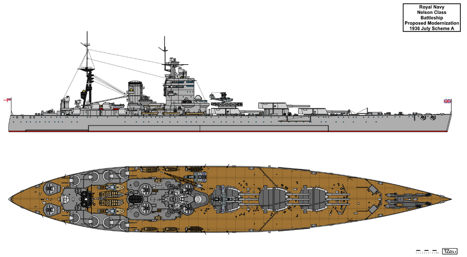
Scheme A:
8x2 5,25” + 4x8 40mm Pom-Poms
No Hangers only Catapult on X turret (1-3 floatplanes?)
Scheme B:
10x2 4,5” and it’s not clear of 4x8 40mm Pom-Poms in total or 4 Pom-Poms per side but I think it would be the total 4x8 and not the 8x8
Trainable? catapult on the shelter deck eg where the boats were stored and Hanger (2-3 floatplanes?)
Scheme C:
10x2 5,25” and it’s not clear of 4x8 40mm Pom-Poms in total or 4 Pom-Poms per side but I think it would be the total 4x8 and not the 8x8
No Hangers only Catapult on X turret (1-3 floatplanes?)
1937 July Refit:
Part of the above changes were done:
Forward part Deck Armour changes as above (4-3-2,5in, only Nelson received it)
Install 2x HACS Mk III* (Received)
Catapult on the 3rd or X turret (Only Rodney received it)
Additional electric generators at the steering compartment/flat, changes to the supporting mast on top of the bridge (Received)
Remove Torpedo Director Tower (Done)
1937 November:
Replace the 6” and 4,7” guns by 10x2 5,25”
All 6” Director Control Tower to be replaced by DP directors (I presume the circular one used on the KGVs)
4x8 40mm Pom-Poms instead of two, the extra two to be located on the quarterdeck (fantail? where the old 4,7” guns were located?)
DTSD Wanted 6 mountings so maybe extra two on top of the 2nd or B turret?
DTSD wanted a KGV style cross-deck catapult
1938 June: (Drawing should exists in the official papers)
Austere new secondary armament of 6x2 5,25” replacing the 6” turrets
4x8 40mm Pom-Pom (2 abeam the bridge not sure if direct on both sides or somewhat aft or somewhat forward and 2 abeam the funnel likely at their current position in place of the Torpedo Control Tower)
2x HACS aft on the very aft close to the 3rd pair of 5,25” turrets
Catapult on the 3rd or X turret and 3 aircraft (1 on catapult 1-1 on each side and behind /abeam of the 3rd turret) which suggests two heavy cranes on deck or attached to the bridge structure
Note this was Scheme B according to the sketch in the papers)
1938 July???
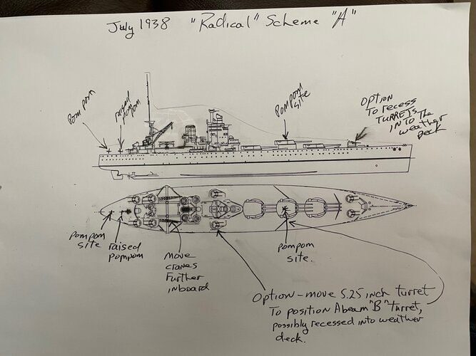
New Scheme A:
8x2 5,25” Fridmans describes two forward of the 1st or A turret and two aft implying either 4 turrets in front of the A turret (unlikely) and 2-2 in place of the 6” turrets, or as we think should be logical:
3-3 in place of the 6” turrets and 1-1 likely side by side in front of the A turret likely just behind the forwardmost breakwater as that is where the 9°elevation and 15°training arcs restrictions suggests
Belt armour might be extended forward to “allow for pitching and wave profile” whatever that means. Probably as a way for increasing stability by re-distributing weight more forward.
Alternatively they can be recessed for a lower profile.
Hanger aft of the funnel and 100ft (QE style) cross-deck catapult
Rebuild the bridge to look like that of the QEs (Warspite style maybe?)
New machinery for 70.000shp (First mention of machinery upgrade) for 25,5knots at 36.000tons
10ft taller funnel and (partial?) removal of uptake protection
Removal of the internal sloped belt armour and replace it with an external one, again no mention if it was to be inclined/sloped or vertical ala KGV style. base thickness not changes so 14” over magazines and 13” over machinery but it was to be tapered to 6 and 7” respectively and the magazine one to be deeper by 2ft
extra 4” and 2,”5 deck armour between the current deck and the sides at magazines and machinery respectively so this would be equivalent to the sloped deck of WW1 era ships I think
New Scheme B:
Same as above but the forwardmost 5,25” turrets moved to abreast the bridge, I presume out of the way of the 3rd turrets firing line.
1938 May:
The missing refits for Rodney was prepared:
deck armour extension
re-wiring
two more octuple Pom-Pom
Refit not carried out
1938 September:
Controller asked and DNC ordered a reconstruction:
6x2 5,25”
6x8 40mm Pom-Poms
Modified side armour. I presume the replacement of the internal belt armour to external one.
New “maximum power” machinery, likely the proposed 70.000shp
Removal of the conning tower and installation of modern bridge, I presume the QE, Warspite or KGV style bridge.
Aircraft and Catapult installation, not sure which version was considered at this time: X turret catapult and 1-3 aircraft, hanger aft of the funnel and cross deck catapult (1-3 aircraft), trainable catapult at the shelter deck and maybe hanger?
Splinterproof poretction between main and middle decks
1939 March:
Replacement of internal belt armour to external one
New machinery, likely the 70.000shp one
High-Angle re-armament (Unknown which proposal)
Catapult on top of x turret, 1-3 aircrafts?
New Bridge, likely ones done for QE, Warspite or KGV/Lion
Removal of Torpedo Tubes
1943 April:
Short Term variant:
8-12 4” AA instead of the 4,7” and 6” guns
Ultimate variant:
8x2 5,25” instead of the 4,7” and 6” guns
9x8 40mm Pom-Poms, apart from the then current arrangement (1-1 in place of the old aft 6” Directors/Rangefinders, and 1-1 next to the funnel) likely 2 extra mounts on the quarterdeck and one on top of turret B
50-60 20mm Oerlikons, like mix of single and twin
Re-wiring
1943 July: (Drawings should exists of the various schemes)
Variant A:
8x2 4,5”
Unknown number of light AA but likely as described below
Variant B:
10x2 4” and 4 Mk VI Directors
12x8 40mm Pom-Poms, not sure how these should be placed. Apart from 4 mountings already exists, 2 more on the quarterdeck, 2 behind the funnel and 2 on top of the conning tower where the 40mm Bofors mounts will be, and the last two maybe in front of the A turret or on top of B and X turrets.
Variant C or temporary measure:
4x2 4”
9-10x8 40mm Pom-Poms and unknown number of Oerlikons: in place of the after 6” turrets and the vacant space of the 4,7” guns. Later Friedman states that 1-1 Pom-Poms were to be put in the vacant space and a 3rd one atop Turret B so a layout of 2 on the quarterdeck, 4 around the funnel, 2 in place of the 4,7” guns and 1-2 atop B and maybe X turret (for a 10th mounting)
No machinery or belt armour replacement
DGD’s proposal 1:
4x2 5,25” with HA/LA Directors
Then Friedman states something weird: “The old 4.7in guns might either be left in place or replaced by two twins each side. The result would be the desired fourcornered ship”
I’m not sure how to imagine this proposal:
4x2 5,25” in place of the 6” while the rest of the 4,7” remains untouched?
4x2 5,25” in place of the 6” while an extra 4x2 5,25” in place of the 4,7” superstrcutre mounted ones (The quartedeck ones got removed)?
8x2 5,25 in place of the 6” ones?
DNC Interim battery:
8x2 4” in place of the 6” turrets
DNC Ultimate Battery:
8x2 5x25” in place of the 6” turrets
Two Mark IV GB or Mark VI directors with type 285 radars replacing the 6” ones on top of the bridge with an extra two directors aft ont he mainmast replacing and thus relocating the octuple Pom-Poms there (This was where the aft 6” directors were located at)
52x 20mm Oerlikons 2x2 and 48x1 (Nelson) or 52x1 (Rodney)
DGD proposal 2:
8x2 5x25” in place of the 6” turrets
4x Mark VI directors with Type 275 radar
9x8 40mm Pom-Poms 3 in place of the 4,7” guns
24-18 20mm Oerlikons (4x2 12x1 in Nelson, 2x2 14x1 Rodney) Seems like the numbers does not add up… or that 24 would be like 20 or 16 instead of 12 single oerlikons.
DGD proposal 3:
As above but with 8x2 4,5” BD mountings instead of the 5,25” guns
DGD proposal 4:
4x2 4” in place of the forward 4,7” guns and 1-1 octuple Pom-Poms in place of the after 4,7” ones
After pair of 6” turrets replaced by Pom-Poms, not sure if the 1st and superfiring 2nd pair would be retained or not
DGD Optimum battery:
10x2 4,5” BD alternatively 4” twins instead of the BD mountings
4 corner HA/LA Director arrangement with blind fire ability
9x4 or 9x8 40mm Pom-Poms
50-60 20mm Oerlikons (likely mix of twin and singles)
Deck armour improvement for Rodney
1943 September: (Plans and wind model test should exists)
USN/BAD (British Admiralty Delegation) Proposal 1 for Nelson:
6x2 5”/54 Mark 16 turrets in place of the 6” ones
4 Mark 37 directors with British Type 275 radars on supports on the plotting platform and aft of the mainmast on the shelter deck.
Main battery directors (I presume both) to be fitted with Type 274 radars and two 16in Barrage directors for B and X turret (I don’t know what would be these or how they would look like)
9x8 40mm Pom-Poms: 1 Pom-Pom to replace the revolving armoured gun director tower (So that was that weird object above the conning tower!) 4 aft of the superstructure if I deduce right where the aft 4,7” single guns were located and where the fantail Pom-Pom was at, the two next to the funnel would remain, the two near the Mainmast would be moved to the Boat Stowage area and the B turret one would remain
4x2 and 48x1 20mm Oerlikons
USN/BAD (British Admiralty Delegation) Proposal 2 for Nelson:
8x2 5”/38 Mark 12 turrets in place of the 6” ones abaft the funnel
8x4 40mm Bofors guns instead of the Pom-Poms: 1 on B turret, 1 on the extreme aft, 1-1 next to the bridge at the shelter deck, 1-1 fore side of the funnel and 1-1 near the tripod mast
Funnel to be heightened
Deckhouse constructed for the 5” turrets with a similar look to that of the Modernized California class Battleships.
Tower bridge to be replaced similar to Valiant or KGV with more forward protruding Compass platform.
4 Mark 37 directors in Diamond and not square arrangement. On what remained of the conning tower a Mark 37 director was placed with the other centerline one behind the tripod mast overwatching the aft 16” DCT. While the last two on both sides and slightly behind of the bridge structure.


