Broncazonk said:
shockonlip said:
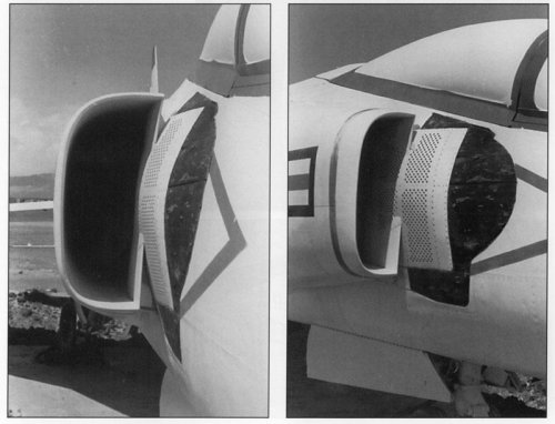
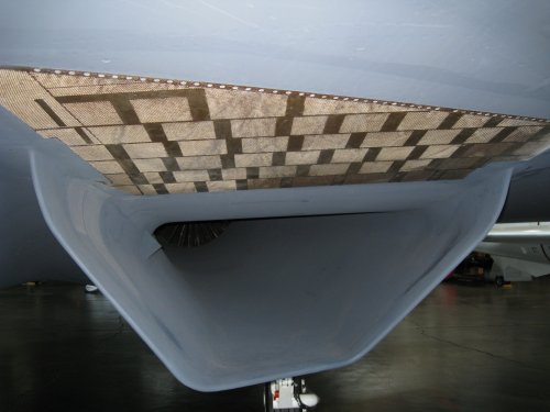
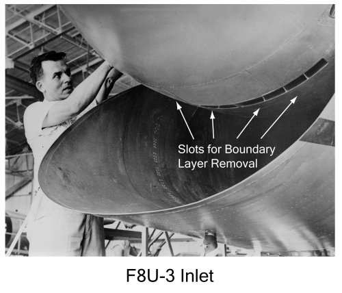
On the other side of the inlet throat was the
sugar scoop inlet....
Can the sugar scoop inlet of the F-8U3 be considered a three-dimensional inlet? ...
Does it make a difference whether the scoop part is under the intake inlet or can it be
over ...
outside ...
a pair ... mounted on the sides of the aircraft?
...
Bronc
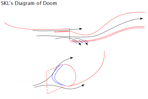
So let's look at the inlet for a moment.
What do we see?
We see a cone above a sugar scoop at the front of the airplane.
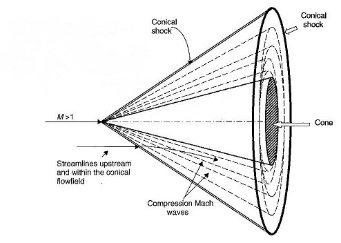
Both the cone and the sugar scoop will generate a shock.
The cone will generate a cone shaped shock. This shock is definitely
a 3-D shock. You should get a good basic aerodynamics book. I
would recommend one of John D. Anderson's books. I really like
his "Modern Compressible Flow", but he has many books that are
good. The losses in the flow through a 3-D cone shock are smaller
than the losses through a 2-D wedge shock at the same angle.
For example, flow through a cone shock generated by a 30 deg. cone
are less than losses due to flow through a 2-D wedge shock caused
by a 30 deg wedge.
The sugar scoop will also generate a 3-D shock.
And then at the throat of the inlet will be the normal shock that takes the
flow subsonic.
Now inside the inlet there is a duct from the throat back to the turbojet's
compressor face.
Because the cockpit is on the top part of the airframe, at the front, that
duct must run through the bottom part of the airframe.
If at the front of the airplane, you put the sugar scoop on the top, and the
cone at the bottom, or the sugar scoop on the sides, the duct we are
discussing would have a tougher time clearing the cockpit volume, plus the
duct would be longer, and more complex adding drag and complexity.
The radar for the production versions of the F8U-3 fit inside the cone, and I
am sure there were benefits from that because the cone is on the top, right
in front of the cockpit and its associated electronics and instrument panel.
At higher mach, there is potentially cooling that has to be done, perhaps for
the electronics. So having this stuff close together probably has
benefits as well because you can cool one electronics section that
is all together, instead of an electronics bay in the cockpit and a radar
electronics bay on a bottom mounted cone.
And the purpose of the inlet is to pass a certain air mass flow rate to the
turbojet. So calculations are done that determine how wide and high the inlet
has to be to pass the required air mass flow rate at different flight speeds
and throttle settings.
I hope this helps.
So it isn't necessarily that something can be done, but does doing that fit in
with everything else.

")