
You are using an out of date browser. It may not display this or other websites correctly.
You should upgrade or use an alternative browser.
You should upgrade or use an alternative browser.
Hawker Siddeley Type 1022
- Thread starter Barrington Bond
- Start date
- Joined
- 21 December 2006
- Messages
- 1,243
- Reaction score
- 1,095
Thanks for posting. From NAL?
I love the HS Advanced Projects designs. Almost all entirely impractical. Their motto must have been 'Simplicity is NOT allowed'!
(see also http://www.secretprojects.co.uk/forum/index.php/topic,14054)
I love the HS Advanced Projects designs. Almost all entirely impractical. Their motto must have been 'Simplicity is NOT allowed'!
(see also http://www.secretprojects.co.uk/forum/index.php/topic,14054)
shedofdread
ACCESS: Top Secret
- Joined
- 14 November 2009
- Messages
- 593
- Reaction score
- 400
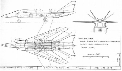
I'm intrigued (don't worry - it's par for the course...) - that's a V-tail, right? And it folds out presumably to go below decks? However it's the angle that got me - very steep for adequate pitch control or is that being acheived via some other method?
As ever, I'm amazed where people dredge things like this up from but wherever they come from, thank you for posting.
As ever, I'm amazed where people dredge things like this up from but wherever they come from, thank you for posting.
A
AAAdrone
Guest
It's the missiles being mounted on rails above the wings that are interesting as well as that V-tail design. Those wing stations must have been a nightmare to fit with missiles for the ground crew.
I know the British have used those wing station positions before in extant designs but I can clearly see why it never caught on.
I know the British have used those wing station positions before in extant designs but I can clearly see why it never caught on.
O
Overkiller
Guest
AAAdrone said:It's the missiles being mounted on rails above the wings that are interesting as well as that V-tail design. Those wing stations must have been a nightmare to fit with missiles for the ground crew.
I know the British have used those wing station positions before in extant designs but I can clearly see why it never caught on.
I may well be incorrect in my interpretation of the drawing, but I don't think those missiles were on above wing pylons, it looks like they are actually dorsally mounted on the upper fuselage, rather like a Phantoms semi conformal (but ventrally located) carriage stations.
cheers
Duncan
PS - Nice drawing, thanks for posting!
- Joined
- 21 December 2006
- Messages
- 1,243
- Reaction score
- 1,095
shedofdread said:I'm intrigued (don't worry - it's par for the course...) - that's a V-tail, right? And it folds out presumably to go below decks? However it's the angle that got me - very steep for adequate pitch control or is that being acheived via some other method?
It may be that the tailerons/finevators (I made that last one up!) are variable to address the fact that in supersonic flight the rear shift of the aerodynamic centre requires more fin area (the reason the Tornado has such a large fin). Or perhaps to stop dud missile motors leading to ejected missiles hitting them? Or they may be variable to allow the tea trolley of the chaps re-loading the missiles to get in position... The mounting and actuator designs would have been interesting in any case.
The HS Advanced Projects Group were all about thinking aloud. But their designs were seldom pursued very far - a few cheap, low speed models were tested (http://www.secretprojects.co.uk/forum/index.php/topic,1396). However, there was a version of the 1022 drawn with a BS.100/3 engine too. And why not?! I am almost surprised they did not use lift jets for pitch contol. Oh, hang on... http://www.secretprojects.co.uk/forum/index.php/topic,14054
shedofdread
ACCESS: Top Secret
- Joined
- 14 November 2009
- Messages
- 593
- Reaction score
- 400
I'd be surprised if that angle were to be variable in-flight. Yes, you're right that more fin is needed in supersonic flight but so is tailplane area and with this set-up you can have one OR the other. Hmmmmm....
Also, the loads on the drive mechanism could be significant to say the least and with that would of course come a weight penalty. However, if it is a 'thinking aloud' excercise, some of these things matter slightly less...
Also, the loads on the drive mechanism could be significant to say the least and with that would of course come a weight penalty. However, if it is a 'thinking aloud' excercise, some of these things matter slightly less...
- Joined
- 21 December 2006
- Messages
- 1,243
- Reaction score
- 1,095
It may also be that the angle of the fin/tails are related to the wing sweep, as that also affects how much pitch control you need. Note that the wings appear to have no control surfaces on them too. But complexity is the result, whatever the cause.
Digging in some notes I see there was also an Olympus 593 powered version of the 1022 drawn.
EDIT: IIRC (don't have Project Cancelled to hand) one of the Folland Fo.147 VG designs had similarly variable tailplanes. And as HS APG was created using staff from all over the group, maybe there is a link?
shedofdread
ACCESS: Top Secret
- Joined
- 14 November 2009
- Messages
- 593
- Reaction score
- 400
Indeed, but without ailerons or [apparently] roll-control spoilers, you aren't going to control the roll axis from a V-tail. The plot thickens...
Trailing - edge slot, coanda effect type ailerons / flaps perchance?")
Trailing - edge slot, coanda effect type ailerons / flaps perchance?
- Joined
- 21 December 2006
- Messages
- 1,243
- Reaction score
- 1,095
shedofdread said:Trailing - edge slot, coanda effect type ailerons / flaps perchance?
If it's APG, it'll be the most complex!
A
AAAdrone
Guest
Overkiller said:AAAdrone said:It's the missiles being mounted on rails above the wings that are interesting as well as that V-tail design. Those wing stations must have been a nightmare to fit with missiles for the ground crew.
I know the British have used those wing station positions before in extant designs but I can clearly see why it never caught on.
I may well be incorrect in my interpretation of the drawing, but I don't think those missiles were on above wing pylons, it looks like they are actually dorsally mounted on the upper fuselage, rather like a Phantoms semi conformal (but ventrally located) carriage stations.
cheers
Duncan
PS - Nice drawing, thanks for posting!
It does appear that way. Unfortunately if that were the case then I can only imagine the issues of clearance in case one had to jettison stores. The conformal ejector rack is going to be launching against gravity so if there is a dud motor or if one merely wishes to fire the weapon then he better hope the rack isn't broken.
Again, I can see why ventral conformal launch racks didn't catch on either.
Similar threads
-
-
 Hawker Siddeley Advanced Projects Group Designations
- Started by overscan (PaulMM)
- Replies: 2
-
 Blackburn SP.62 and Hawker Siddeley « Helicrane » projects
- Started by hesham
- Replies: 21
-
 The Hawker P.1052, P.1072 and P.1081.
- Started by blackkite
- Replies: 12
-
