I post this thread here (and not in the Secret Army Projects, as the ultimate user) because the information is taken from a report written following a meeting between Italian and German aeronautical experts to exchange technical knowledge in Germany in October 1941. The report is ABSOLUTELY authentic and is located in the State Archives in Rome, Fondo Ministero dell'aeronautica, Gabinetto, anno 1942, busta 144, fascicolo 12-X-8, Collaborazione italo-tedesca nel campo delle ricerche d'interesse aeronautico Vol. 1 (Ministry of Aeronautics Collection, Cabinet, 1942, folder 144, file 12-X-8, Italian-German Collaboration in the Field of Aeronautical Research, Vol. 1). The gangway must have existed (the Italians watched a video about it), perhaps the shorter version, because the 24-, 40-meter versions could have been difficult to tow...
Italian Text.
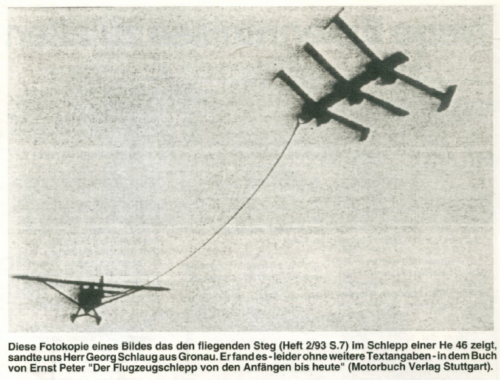
Passerella volante. Per poter fornire rapidamente a truppe in movimento il mezzo di attraversare corsi d'acqua è stata ideata e realizzata una passerella volante, che può essere lunga 16, 24 o 40 m. Le passerella è appoggiata su 4 galleggianti simili ai galleggianti laterali degli ìdrovolanti, i quali portano sul fondo un pattino destinato a permettere la partenza su terra, ed è munita di due ali di uguale apertura alare disposte in tandem. Queste ali portano ciascuna alle estremità due derive fisse, di maggior superficie quelle posteriori; le anteriori, più piccole e instabilizzanti, servono a smorzare le oscillacicni d'imbardata. Ciascuna delle ali è unita alla passerella con due soli bulloni eliminabili mediante carica di esplosivo. La passerella viene rimorchiata in volo da un aeroplano fino al corso d'acqua, dove deve essere impiegata; l'aeroplano si abbbassa in volo quanto più gli è possibile e molla la passerella che cade in acqua sui galleggianti. All'atto dell'urto, la pressione idrodinamica agente sui piattelli fa esplodere i bulloni e le ali si staccano. E' stata vista una cinematorgafia della partenza, del volo e del varo della passerella. La passerella in aria subisce forti oscillazioni e atterra prendendo un forte colpo a deformandosi sensibilmente.
English (google) translation:
Flying gangway. To quickly provide troops on the move with a means of crossing waterways, a flying gangway was designed and built. It can be 16, 24, or 40 meters long. The gangway rests on four floats similar to the lateral floats of seaplanes, which have a skid on the bottom to allow for takeoff on land. It is equipped with two wings of equal wingspan, arranged in tandem. Each wing has two fixed fins at its ends: the rear ones are larger; the front ones, smaller and more unstabilizing, serve to dampen yaw oscillations. Each wing is connected to the gangway with just two bolts, which can be removed with an explosive charge. The gangway is towed by an airplane to the waterway where it is to be deployed; the airplane descends as low as possible and releases the gangway, which falls into the water on the floats. Upon impact, the hydrodynamic pressure acting on the plates causes the bolts to explode, and the wings to detach. A cinematographic video of the takeoff, flight, and deployment of the gangway was observed. The gangway oscillates strongly in the air and lands with a sharp impact, deforming significantly.