KazuyaR
ACCESS: Restricted
- Joined
- 7 June 2019
- Messages
- 9
- Reaction score
- 8
Something like a year ago I was a little bored and did some research on Legacy and Super Hornet's AMAD and APU. Interestingly enough, the topic itself appears to be quite poorly researched and rarely talked about, though being fairly interesting in terms of aircraft design overall and in terms of how different operational requirements, manufacturers, and air force doctrines influence the layout and characteristics of these systems. I will drop all the info I've found in this thread, so at least it won't disappear somewhere in the depths of my hard drive.
So, let's start this thread with the Hornet's AMAD and APU systems.
Sources:
So, let's start this thread with the Hornet's AMAD and APU systems.
The Airframe Mounted Accessory Drive (AMAD) is essentially a gearbox designed to transfer power from the APU or engine to generators, hydraulic and fuel pumps. It also plays a key role in engine startup by transferring power from APU to the air turbine starter (ATS). F/A-18's secondary power system contains two AMADs and a single APU. During normal operation, each AMAD is mechanically driven by its corresponding engine through a power transmission shaft/power take-off shaft (PTS) and is used to drive a fuel boost/motive flow pump, an AC/DC electrical generator, and a 3000/5000 psi hydraulic pump. Pneumatic pressure is used to rotate an ATS on each AMAD for engine crank/start capability. Either AMAD (but not both at the same time) may also be driven pneumatically through opposite engine bleed air (crossbleed), or an external air supply. For ground maintenance use, either AMAD can be decoupled from its engine, allowing pneumatic pressure to drive the AMAD and its accessories.[1]

Figure 1. Secondary Power Supply schematics.
Both Legacy and Super Hornet AMADs are produced and overhauled by Triumph Group. Aeronautical Systems Inc. (ASI) also takes part, at least in overhaul, but I don't know for sure if they are also engaged in manufacturing. It is important to note, that F/A-18E/F/G are equipped with a different type of AMAD gearbox compared to the F/A-18A/B/C/D.
As mentioned earlier, AMAD is connected to the engine via PTS shaft and high-speed drive. In Legacy Hornets, drive is geared at a ratio of 1:1 through two right-angled drives from the high-speed engine rotor (16810 rpm being 100% speed). The AMAD gearbox has several accessory pads, and mounted on the front face are the electrical generator, hydraulic pump, fuel boost pump and ATS. When starting, the power flow is in a 'reverse' direction from the ATS through the AMAD gearbox to the engine. A manually-operated free-wheel is incorporated in the AMAD gearbox input to enable disconnection of the drive to the engine so as to permit ground running of the accessories from the air turbine. The gearbox is mounted in two steel spherical mounts each side of the gearbox, with an upper elastomeric mount. The lower inboard mount is fixed, the outer one sliding on the spindle, as is the practice with the main engine mounts. Additional restraint to the gearbox is brought about by the fuel and hydraulic pipe connections to the fuel boost pump and hydraulic pump.[2]

Figure 2. AMAD location.
In 2005, it was declared by the manufacturer that each AMAD can handle at least 7800 hrs under typical operating conditions.[3] But, it seems to be that during testing they didn't took into account all possible different and rapid loads which affect the gearbox during flight and on the ground. Several major concerns were discovered during flight operations. It is known that first major problem was encountered by RAAF in February 1993, when F/A-18A A21-45 suffered an in-flight fire due to the failure of the PTS shaft bearing. Second accident occurred in November 1993, when F/A-18A A21-22 under the same circumstances suffered an in-flight fire, which resulted in significant heat damage to the internal bulkhead. This particular aircraft was shipped to San Diego for $4M repairs and returned to service in 1995. Prior to the accidents, several other problems were reported within AMAD gearboxes. These were: loose bearing cage pins, lower side mounts wear, oil pump drive shearing (due to the ingress of debris to the pump) and failure of oil pump drive gears. Deterioration of the gearbox elastomeric top mount and the semi-spherical metal side mounts has also been a problem. Of course, RAAF immediately requested an investigation. Damaged gearboxes and shafts were sent for examination, as well as several other that came in for repairs and overhaul. Also, they equipped 10 random F/A-18s with special-purpose vibration measuring equipment. Especially detailed examination was carried out for the PTS assembly. The PTS assembly consists itself of 19E215-1 titanium driveshaft, made by Lucas Aerospace, -347 sleeve/-348 shaft, and PTS input ball bearing 42312-366. Here are the main conclusions of the investigation:

Figure 3. Super Hornet AMAD with all accessories at the test stand. You can see the PTS at the right.
Legacy AMAD dry weight is 65 lbs, while total weight with accessories is around 200 lbs. Super Hornet AMAD is a little heavier at 87 lbs of dry weight, and somewhere around 225 lbs of total weight.
Thanks to [2], we also have all views and most characteristics for Legacy AMAD. I will not include all the drawings because it will make the post too long and is not necessary here. But I've attached the PDF doc. so everybody can open it and look by themselves.

Figure 4. Legacy AMAD internal layout.
And, of course, I will also leave here all pictures of this gearbox I've found, whether they are high- or low-quality, because, in fact, there are not much of them exist in the Net. As well as the info itself, especially about Super Hornet AMADs.

Figure 5. Super Hornet AMAD front view. It is said by the author, that this particular example was sent in for repairs after GCU (generator) bearing failure. Source: jwiggs152 Reddit.
Sometime in late 2000s/early 2010s, US NAVY encountered yet another set of AMAD issues, at this time with Super Hornets - severe damage of ATS pads due to fretting corrosion, internal casing damage caused by gear spin-outs (looks like hydraulic/fuel pump gears can sometimes run away), extensive wear of converter generator unit (GCU) rotor journals and hydraulic gear shaft seal surfaces. Seems to be that the ATS pad fretting issue was also present in Legacy Hornet AMADs, but they had fretting damage to PTS snout surface as well, and that probably indicates that vibration issues were not completely resolved. So, in 2011, with attempt to save those parts, time and money, NAVY engineers decided to try an innovative repair technology, called "Kinetic Metallization" (developed by the Inovati, whose equipment is used for repairs), which itself is a variation of cold spray technique. They machined damaged surfaces (appr. 0.008 deep), sprayed aluminum alloy, and then again machined the pads back to the original dimensions. In 2011, it was estimated that ATS pad repairs costs were around $10,000 per unit, and in 2014 it was estimated that internal repairs (damage caused by runaway gears) were about $2,500 per unit. For example, in 2011 new AMAD unit cost was $85,000, in 2014 - $135,000, in 2017 - $168,000. As of May 2023, 35 AMADs have been repaired by Cold Spray comprising an asset that has over 24,500 flight hours.[4]

Figure 6. Super Hornet AMAD ATS pad fretting corrosion (before repairs).

Figure 7. ATS pad after repairs.

Figure 8. Close-up shot of damaged ATS pad.

Figure 9. Internal damage caused by gear failure in Super Hornet AMAD.

Figure 10. And after repairs. You can also note the internal gear layout.

Figure 11. The same spot at another angle.
Figure 12. Super Hornet AMAD housing without gears. You can see the shiny repaired area.

Figure 13. View from another angle.

Figure 14. Legacy AMAD casing repaired after PTS pad fretting damage.
Figure 15. And another view of repaired Legacy AMAD casing.
Figure 16. The description speaks by itself.

Figure 17. GCU rotor journals before and after repairs.

Figure 18. Hydraulic gear shaft seal surface repairs.

Figure 19. This is how (in this case Legacy) AMAD is sealed with protective covers for transportation or storage.

Figure 20. And super low-quality Legacy AMAD shot.
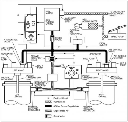
Figure 1. Secondary Power Supply schematics.
Both Legacy and Super Hornet AMADs are produced and overhauled by Triumph Group. Aeronautical Systems Inc. (ASI) also takes part, at least in overhaul, but I don't know for sure if they are also engaged in manufacturing. It is important to note, that F/A-18E/F/G are equipped with a different type of AMAD gearbox compared to the F/A-18A/B/C/D.
As mentioned earlier, AMAD is connected to the engine via PTS shaft and high-speed drive. In Legacy Hornets, drive is geared at a ratio of 1:1 through two right-angled drives from the high-speed engine rotor (16810 rpm being 100% speed). The AMAD gearbox has several accessory pads, and mounted on the front face are the electrical generator, hydraulic pump, fuel boost pump and ATS. When starting, the power flow is in a 'reverse' direction from the ATS through the AMAD gearbox to the engine. A manually-operated free-wheel is incorporated in the AMAD gearbox input to enable disconnection of the drive to the engine so as to permit ground running of the accessories from the air turbine. The gearbox is mounted in two steel spherical mounts each side of the gearbox, with an upper elastomeric mount. The lower inboard mount is fixed, the outer one sliding on the spindle, as is the practice with the main engine mounts. Additional restraint to the gearbox is brought about by the fuel and hydraulic pipe connections to the fuel boost pump and hydraulic pump.[2]
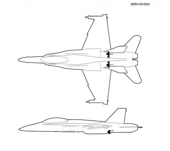
Figure 2. AMAD location.
In 2005, it was declared by the manufacturer that each AMAD can handle at least 7800 hrs under typical operating conditions.[3] But, it seems to be that during testing they didn't took into account all possible different and rapid loads which affect the gearbox during flight and on the ground. Several major concerns were discovered during flight operations. It is known that first major problem was encountered by RAAF in February 1993, when F/A-18A A21-45 suffered an in-flight fire due to the failure of the PTS shaft bearing. Second accident occurred in November 1993, when F/A-18A A21-22 under the same circumstances suffered an in-flight fire, which resulted in significant heat damage to the internal bulkhead. This particular aircraft was shipped to San Diego for $4M repairs and returned to service in 1995. Prior to the accidents, several other problems were reported within AMAD gearboxes. These were: loose bearing cage pins, lower side mounts wear, oil pump drive shearing (due to the ingress of debris to the pump) and failure of oil pump drive gears. Deterioration of the gearbox elastomeric top mount and the semi-spherical metal side mounts has also been a problem. Of course, RAAF immediately requested an investigation. Damaged gearboxes and shafts were sent for examination, as well as several other that came in for repairs and overhaul. Also, they equipped 10 random F/A-18s with special-purpose vibration measuring equipment. Especially detailed examination was carried out for the PTS assembly. The PTS assembly consists itself of 19E215-1 titanium driveshaft, made by Lucas Aerospace, -347 sleeve/-348 shaft, and PTS input ball bearing 42312-366. Here are the main conclusions of the investigation:
- AMAD gearbox input housing vibration measurements have shown very high vibration levels on some aircraft. The vibration appears largely due to unbalance in the driveshaft assembly.
- Measurements of driveshaft motion have confirmed synchronous forward whirl of the driveshaft which couples the engine to the AMAD gearbox The driveshaft orbits are nearly circular.
- The driveshaft system appears to operate below its first critical speed, but the rapid increase in vibration levels at the higher speeds indicates that the first critical speed may not be far above running speed. There is no evidence of significant driveshaft system resonances during the operating speed range of idle to full military power.
- The primary cause of unbalance appears to be clearances in the AMAD gearbox input shaft assembly, in particular of the -347/-348 shafts. These clearances will bring about an initial unbalance of the assembly much greater than individual component balance factors.
- Rotation of the 19E215-1 driveshaft relative to the input PTS assembly can bring about significant reductions in vibration levels.
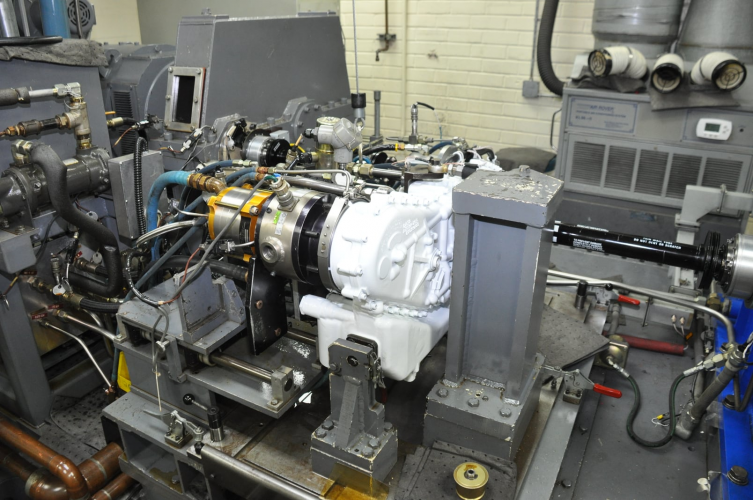
Figure 3. Super Hornet AMAD with all accessories at the test stand. You can see the PTS at the right.
Legacy AMAD dry weight is 65 lbs, while total weight with accessories is around 200 lbs. Super Hornet AMAD is a little heavier at 87 lbs of dry weight, and somewhere around 225 lbs of total weight.
Thanks to [2], we also have all views and most characteristics for Legacy AMAD. I will not include all the drawings because it will make the post too long and is not necessary here. But I've attached the PDF doc. so everybody can open it and look by themselves.
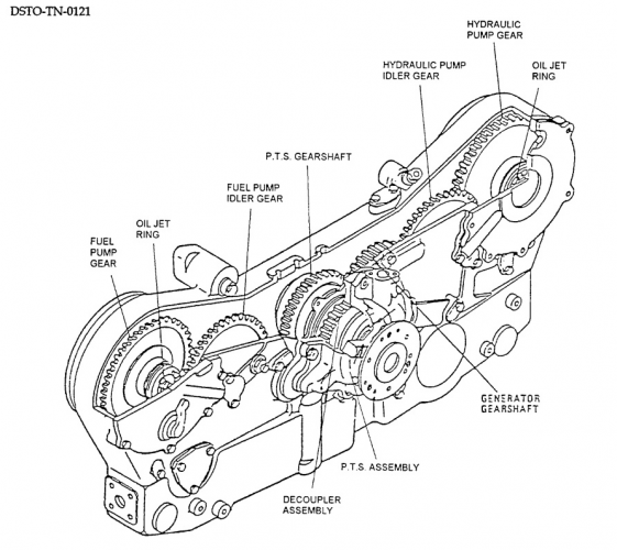
Figure 4. Legacy AMAD internal layout.
And, of course, I will also leave here all pictures of this gearbox I've found, whether they are high- or low-quality, because, in fact, there are not much of them exist in the Net. As well as the info itself, especially about Super Hornet AMADs.
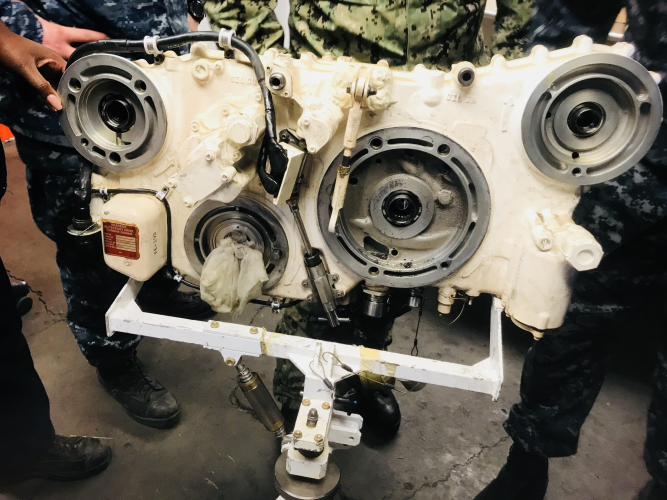
Figure 5. Super Hornet AMAD front view. It is said by the author, that this particular example was sent in for repairs after GCU (generator) bearing failure. Source: jwiggs152 Reddit.
Sometime in late 2000s/early 2010s, US NAVY encountered yet another set of AMAD issues, at this time with Super Hornets - severe damage of ATS pads due to fretting corrosion, internal casing damage caused by gear spin-outs (looks like hydraulic/fuel pump gears can sometimes run away), extensive wear of converter generator unit (GCU) rotor journals and hydraulic gear shaft seal surfaces. Seems to be that the ATS pad fretting issue was also present in Legacy Hornet AMADs, but they had fretting damage to PTS snout surface as well, and that probably indicates that vibration issues were not completely resolved. So, in 2011, with attempt to save those parts, time and money, NAVY engineers decided to try an innovative repair technology, called "Kinetic Metallization" (developed by the Inovati, whose equipment is used for repairs), which itself is a variation of cold spray technique. They machined damaged surfaces (appr. 0.008 deep), sprayed aluminum alloy, and then again machined the pads back to the original dimensions. In 2011, it was estimated that ATS pad repairs costs were around $10,000 per unit, and in 2014 it was estimated that internal repairs (damage caused by runaway gears) were about $2,500 per unit. For example, in 2011 new AMAD unit cost was $85,000, in 2014 - $135,000, in 2017 - $168,000. As of May 2023, 35 AMADs have been repaired by Cold Spray comprising an asset that has over 24,500 flight hours.[4]
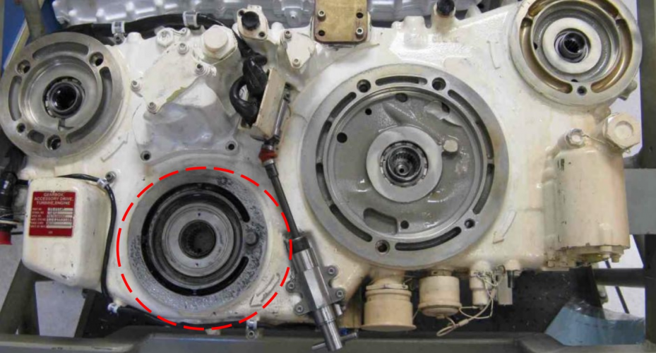
Figure 6. Super Hornet AMAD ATS pad fretting corrosion (before repairs).
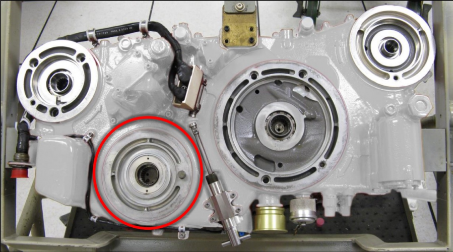
Figure 7. ATS pad after repairs.
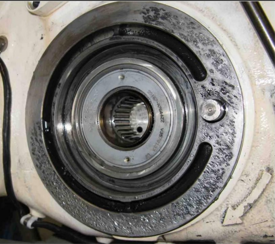
Figure 8. Close-up shot of damaged ATS pad.
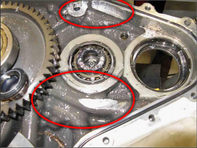
Figure 9. Internal damage caused by gear failure in Super Hornet AMAD.
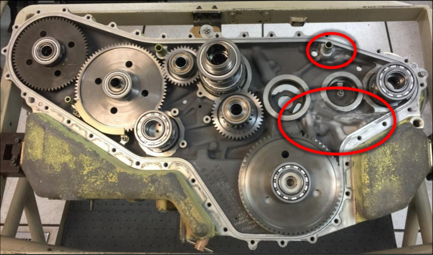
Figure 10. And after repairs. You can also note the internal gear layout.
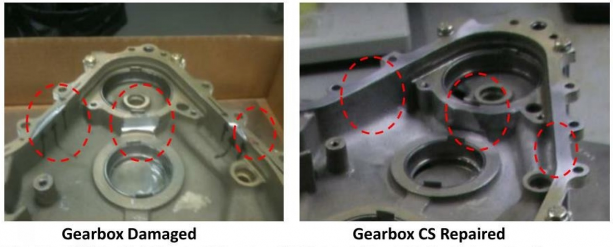
Figure 11. The same spot at another angle.
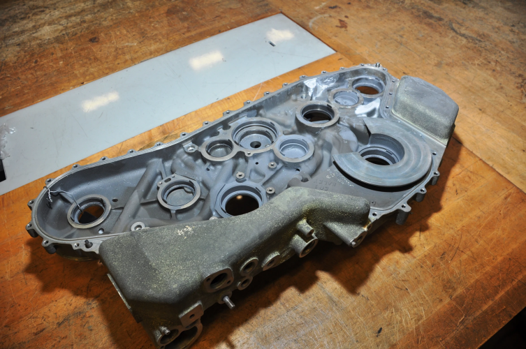
Figure 12. Super Hornet AMAD housing without gears. You can see the shiny repaired area.
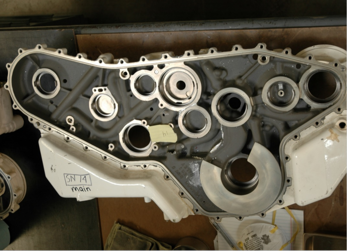
Figure 13. View from another angle.
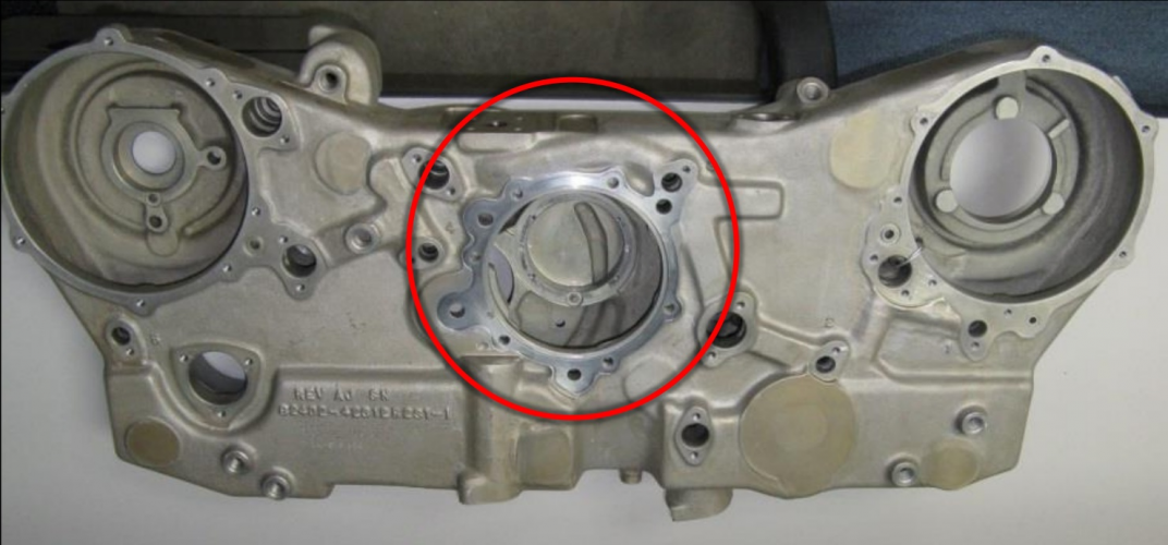
Figure 14. Legacy AMAD casing repaired after PTS pad fretting damage.
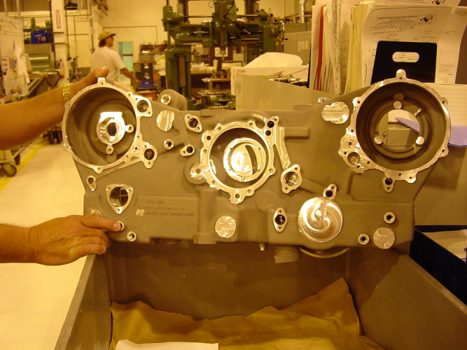
Figure 15. And another view of repaired Legacy AMAD casing.
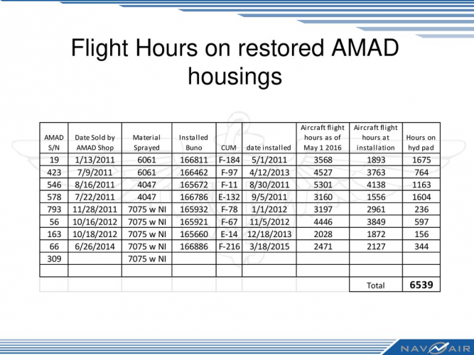
Figure 16. The description speaks by itself.
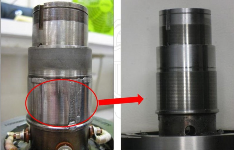
Figure 17. GCU rotor journals before and after repairs.
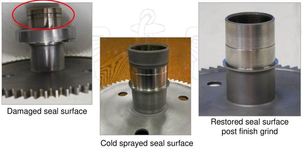
Figure 18. Hydraulic gear shaft seal surface repairs.
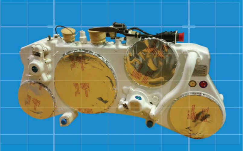
Figure 19. This is how (in this case Legacy) AMAD is sealed with protective covers for transportation or storage.
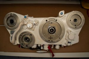
Figure 20. And super low-quality Legacy AMAD shot.
As said earlier, AMAD has several main accessories. These are: GCU, ATS, fuel pump, oil pump. There's, of course, as little info at the Net about them as possible.
The GCU used in Legacy Hornets is a VSH1189-4 model made by GE. For Super Hornets, it is said that they have an updated model, but I don't know for sure. It's weight is 75...115 lbs (34...52 kg), and it is rated at 65kVA, 115V, 400Hz, 3-phase current. In the early 2010s, the cost of a single GCU was around $40,000. It is known that GCU O-rings were prone to failure.
It is also known, that F/A-18s GCU is using a so-called cycloconverter approach. It replaces the constant speed drive and generator for providing 400Hz power. The generator is driven directly by the engine and produces power at frequencies varying with engine speed. For efficiency the output must be at least 2400Hz and a 6 phase. The desired 3-phase, 400Hz power is then extracted electronically by the cycloconverter by switching between these six phases. The switching is performed by Silicon Controlled Rectifiers (SCRs). Voltage regulation is accomplished by control of the field current in the alternators.

Figure 21. GCU. Probably from Super Hornet.

Figure 22. Legacy GCU is being prepared for installation.

Figure 26. Draining oil from AMAD. At the top is GCU (big square box), at the right from it - oil pump.
I still did not found anything useful about ATS and fuel pump. So, the next is hydraulic pump, made by Eaton. Hydraulic power for flight control and utility systems is provided by two 78.9 gpm (295 L/min.), 4480 rpm, variable displacement, pressure compensated inline pumps. Eaton's hydraulic pump PV3-400-5B incorporates a solenoid actuated, dual pressure range compensator, allowing the flight control computer to select either 3000 psi (20,600 kPa) or 5000 psi (34,500 kPa) pressure operation based on flight surface loading.

Figure 27. The pump itself.
Figure 28. Mounted in the AMAD bay.
Also I've found some pictures from eBay listing. This is the exact same model (PV3-400-5B). I don't know whether it is from Hornet or from other aircraft. It is very likely that this model might be used across wider range of aircraft.


Figure 32. Seems to be the red shaft is PTS.
The GCU used in Legacy Hornets is a VSH1189-4 model made by GE. For Super Hornets, it is said that they have an updated model, but I don't know for sure. It's weight is 75...115 lbs (34...52 kg), and it is rated at 65kVA, 115V, 400Hz, 3-phase current. In the early 2010s, the cost of a single GCU was around $40,000. It is known that GCU O-rings were prone to failure.
It is also known, that F/A-18s GCU is using a so-called cycloconverter approach. It replaces the constant speed drive and generator for providing 400Hz power. The generator is driven directly by the engine and produces power at frequencies varying with engine speed. For efficiency the output must be at least 2400Hz and a 6 phase. The desired 3-phase, 400Hz power is then extracted electronically by the cycloconverter by switching between these six phases. The switching is performed by Silicon Controlled Rectifiers (SCRs). Voltage regulation is accomplished by control of the field current in the alternators.
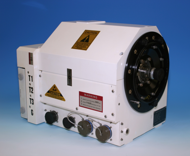
Figure 21. GCU. Probably from Super Hornet.
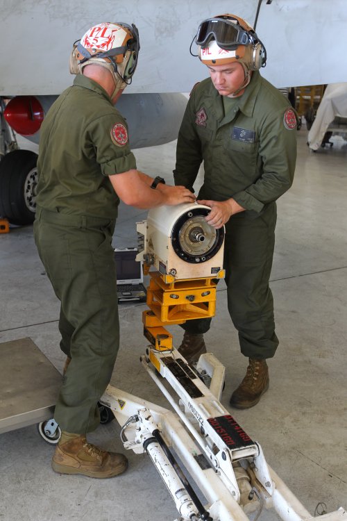
Figure 22. Legacy GCU is being prepared for installation.
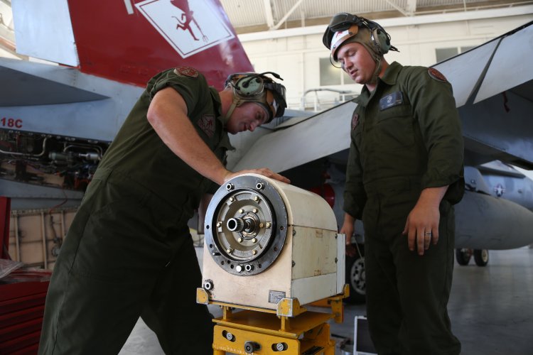
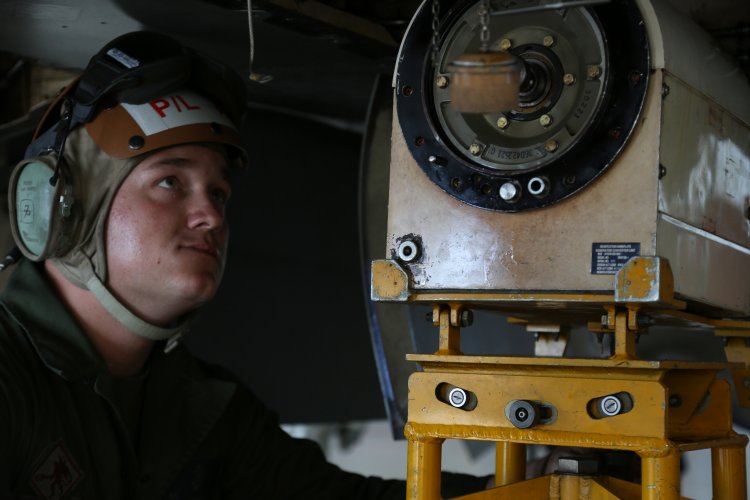
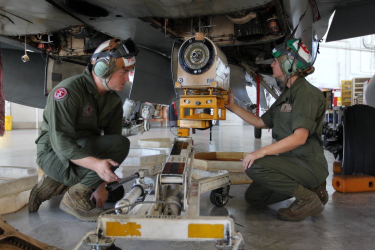

Figure 26. Draining oil from AMAD. At the top is GCU (big square box), at the right from it - oil pump.
I still did not found anything useful about ATS and fuel pump. So, the next is hydraulic pump, made by Eaton. Hydraulic power for flight control and utility systems is provided by two 78.9 gpm (295 L/min.), 4480 rpm, variable displacement, pressure compensated inline pumps. Eaton's hydraulic pump PV3-400-5B incorporates a solenoid actuated, dual pressure range compensator, allowing the flight control computer to select either 3000 psi (20,600 kPa) or 5000 psi (34,500 kPa) pressure operation based on flight surface loading.
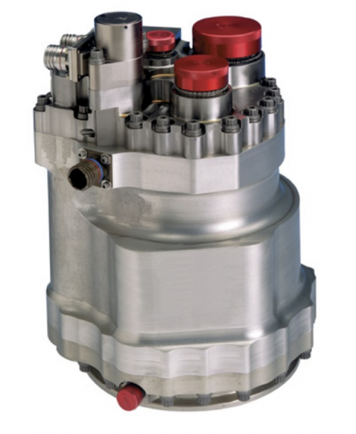
Figure 27. The pump itself.
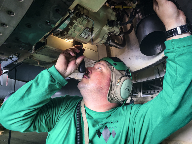
Figure 28. Mounted in the AMAD bay.
Also I've found some pictures from eBay listing. This is the exact same model (PV3-400-5B). I don't know whether it is from Hornet or from other aircraft. It is very likely that this model might be used across wider range of aircraft.
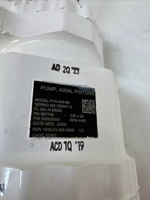
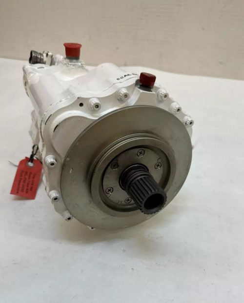
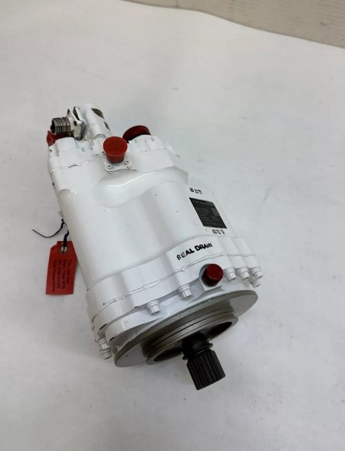
Figure 32. Seems to be the red shaft is PTS.
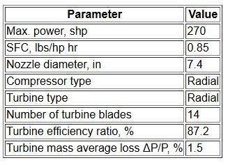
The APU itself is made by Honeywell and is called GTC36-200. Unfortunately, a little is known about this APU. Mostly, it is a typical APU from it's era. The concept employed in this unit is simple - a power section driving a load compressor at shaft speed, with both the engine and the load compressor sharing a common air inlet. Variable inlet guide vanes automatically control the load compressor air delivery in response to a demand signal. Compressor bleed air output is modulated by an actuator that controls inlet guide vane positions. Compressor surge protection is provided by a modulating surge bleed air valve controlled by an airflow sensor. Seems to be that both Legacy and Super Hornets have the same APU model. I've gathered all info I've found in the table below:

At least until mid-1990s compressor impeller was made of forged titanium. In 1992, a project was initiated to replace the titanium impeller with an impeller made from X8019 and 8009 aluminum alloys (which could withstand up to 650 °F), utilizing powder metallurgy technology. I don't know whether was it implemented in mass-production or not.

Figure 33. APU cutaway.
Also, I've found a handful of photos from repair and testing facility at MCAS Cherry Point. The source says that these are Hornet APUs. Here they are:
Figure 34. A row of GTC36-200s.
Figure 37. The test stands are on the left.
Figure 40. You can see the hydraulic motor at the top. It is manufactured by Frisby Aerospace.

Figure 41. APU pricing through the years.
At least until mid-1990s compressor impeller was made of forged titanium. In 1992, a project was initiated to replace the titanium impeller with an impeller made from X8019 and 8009 aluminum alloys (which could withstand up to 650 °F), utilizing powder metallurgy technology. I don't know whether was it implemented in mass-production or not.
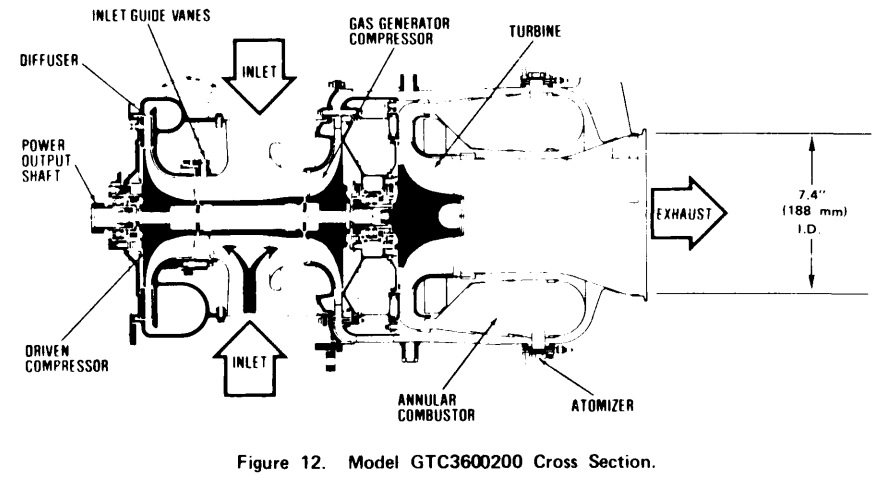
Figure 33. APU cutaway.
Also, I've found a handful of photos from repair and testing facility at MCAS Cherry Point. The source says that these are Hornet APUs. Here they are:
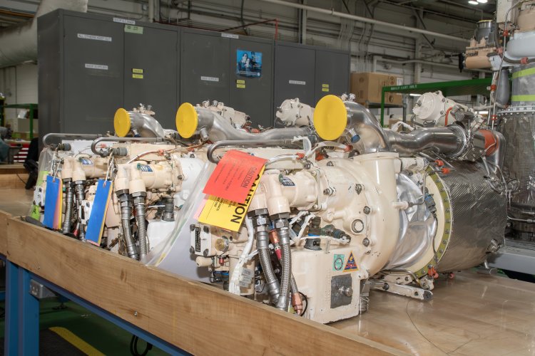
Figure 34. A row of GTC36-200s.
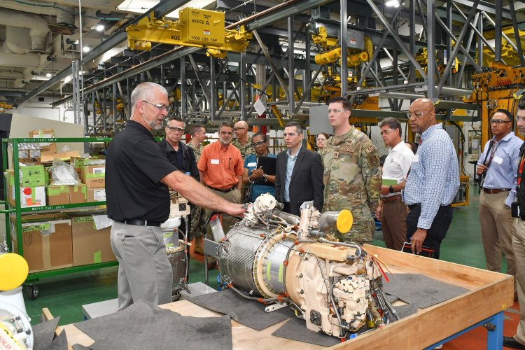
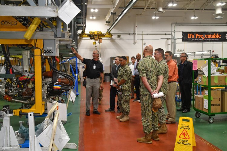
Figure 37. The test stands are on the left.
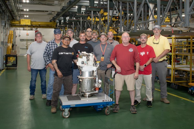
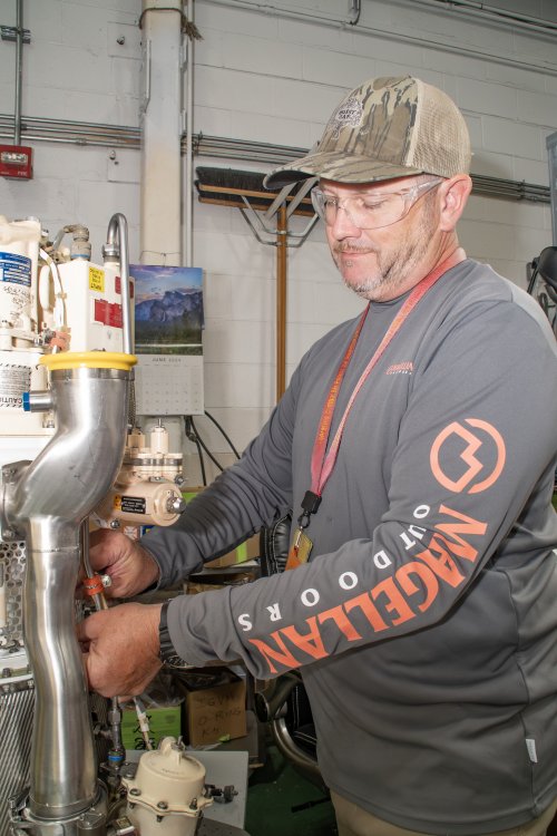
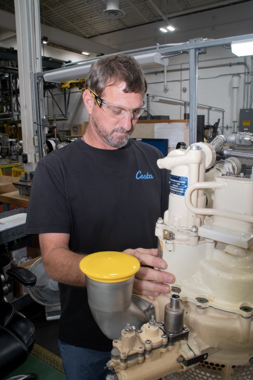
Figure 40. You can see the hydraulic motor at the top. It is manufactured by Frisby Aerospace.
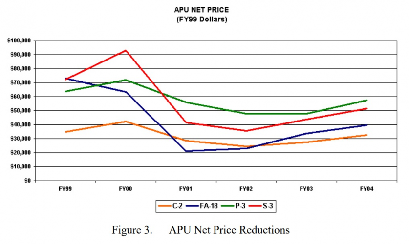
Figure 41. APU pricing through the years.
Sources:
- [1] F/A-18 NATOPS manual
- [2] DSTO-TN-0121: An Investigation of F/A-18 AMAD Gearbox Driveshaft Vibration. Brian Rebbechi; Madeleine Burchill; Gareth Coco; Nov. 1997; 101p
- [3] Triumph Group advertisement brochure
- [4] Various official NAVAIR sources