Comper « Scamp » / « Fly » pusher aircraft project

Thanks Hesham.
I had problems reading the article, to understand the words "stub-wing", "stub-tips", but tle on-line translater BabelFish gave me the French "moignon" for stub, OK.
 
A photograph of the Comper Fly (the single seat prototype for the two seat Scamp) .

[Source: British Light Aeroplanes - Their Evolution, Development and Perfection 1920-1940 (A.W.J.G.Ord-Hume)]
 

Attachments

  • img144.jpg
    img144.jpg
    227.4 KB · Views: 400
.......and two photographs of the Comper Fly under construction (same source as before)
 

Attachments

  • img145.jpg
    img145.jpg
    168.8 KB · Views: 328
  • img146.jpg
    img146.jpg
    95.6 KB · Views: 296
hi,
An attempt was made to develop the scamp into a military version for observation duties during 1939 but the designer died in
a street fight in Hythe in june 1939.(source: the story of british light aeroplane Terence Broughton).
 
Hi
Very interresting.
Are there any drawings/ dimensions/etc. of the Fly?
Thanks
Jan
 
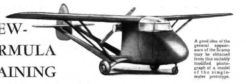
Unfortunately Ord-Hume gives no dimensions for the Fly and those given for the Scamp are only the designer's published estimates and, even then, the information is scant, namely:

Span (folded): 30' 0"
Length (overall): 18' 9"
Cruising speed: 100 mph

Returning to the text of Ord-Hume's essay on the Fly, he says that the wing comprised:

- two lightweight box-spars with braced plywood ribs
- plywood leading edge and the whole fabric covered
- NACA 23012 wing section
- two large fuel tanks outboard of the centre-section

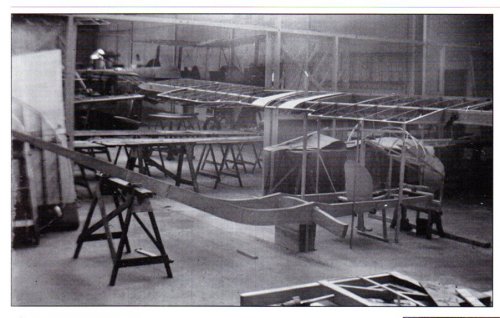
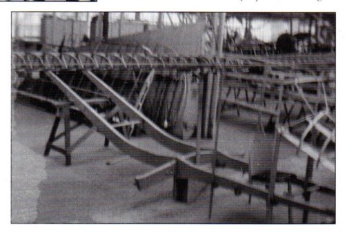
and that the fuselage comprised:

- two long and curved booms of solid, laminated spruce tied at the front with a cross-piece and at the undercarriage lift-strut attachment by a downwards curved beam of substantial thickness
- at the upper ends of this beam, a bracket which provided an attachment for the lift-struts and a pivot-point for the beam extensions forming the undercarriage leg upper attachment points
- undercarriage leg lower attachment points in the form of rubber cords to provide springing
- a bracket extending aft from the end of the beam and braced to the fuselage boom by steel tube forming the radius-rod attachment (all of which was contained in the undercarriage fairing).

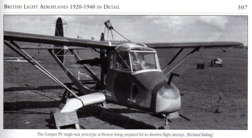
He also says that the Fly was powered by a 40 hp twin cylinder Praga engine driving a four bladed propellor.

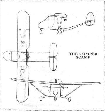
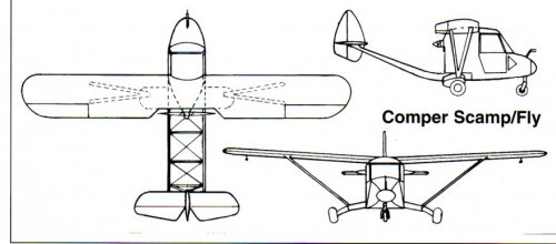
There is also a drawing but it is not clear whether it is intended to be of the Fly or the Scamp. However I'll scan and post this later.
 
Thanks, very good information.
I am looking forward to the drawing.
Jan
 
Does anyone know what's going on with the odd bracing around the vertical fin and the cylindrical object above the engine in the photo of the Comper Fly in the first post above by avion ancien?

avion ancien said:
A photograph of the Comper Fly (the single seat prototype for the two seat Scamp) .

[Source: British Light Aeroplanes - Their Evolution, Development and Perfection 1920-1940 (A.W.J.G.Ord-Hume)]
 
The small horizontal strut just in front of the fin looks thicker and the cylindrical object could be
a camera, I think. Maybe smoke was produced for aerodynamic testing in fligt and the results
filmed ?
 
IMO, the cylinder above the engine is the container for an anti-spin parachute, used during stall/spin testing. The 'bracing' around the fin and rudder is a guard to prevent the parachute cable getting caught in the rudder gap and jamming it.

cheers,
Robin.
 
Jemiba said:
Maybe smoke was produced for aerodynamic testing in fligt and the results
filmed ?

Ord-Hume says that the Fly was both overweight and underpowered, which probably was the reason why "after three weeks of intensive attempts and adjustments, during which time the machine failed to leave the ground, it was abandoned and taken to the home of Capt. Fane and was never seen again"!

Below is the drawing which appears in Ord-Hume's magnum opus. I suspect that it may be of the Scamp rather than the Fly.
 

Attachments

  • comper.jpg
    comper.jpg
    60.1 KB · Views: 63
robunos said:
IMO, the cylinder above the engine is the container for an anti-spin parachute, used during stall/spin testing. The 'bracing' around the fin and rudder is a guard to prevent the parachute cable getting caught in the rudder gap and jamming it.

cheers,
Robin.

On this subject Ord-Hume says that the Fly had "an anti-spin 'chute canister supported above the wing centre section in front of the four-bladed propellor".
 
I suppose that the inevitable progression of this thread is the Fane F1/40, which was developed out of (or if Ord-Hume is to be believed, constructed from the part completed prototype airframe of) the Comper Scamp.
 
If I look to the picture and drawing, is my opinion the drawing the Fly.
Jan
 
A photograph of the Fane F1/40 (from The Aeroplane). The dimensions of it were:

Span: 37' 0"
Length: 23' 5"
All up weight: 1500 lb

It was powered by a 80 hp Continental A-80.
 

Attachments

  • fane.jpg
    fane.jpg
    101.5 KB · Views: 156
I'm afraid that I don't have a drawing but apparently there is a three view in the Aeroplane Spotter of 24 August 1944, if anyone has a copy of this magazine!
 
Jan den Das, it's seven years later, but if you still want it, here's the GA drawing of the Fane F.1/40 AOP aircraft. Source Aeroplane Monthly May 1977
Fane AOP -3-view.jpg
 

Similar threads

Back
Top Bottom