- Joined
- 11 February 2010
- Messages
- 1,650
- Reaction score
- 2,702
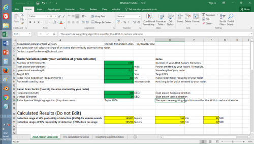
Well as title said. I tried to brew some sort of excel spreadsheet to calculate detection range of radar. Optimized for use on AESA radar and hopefully work good for fighter aircraft application.
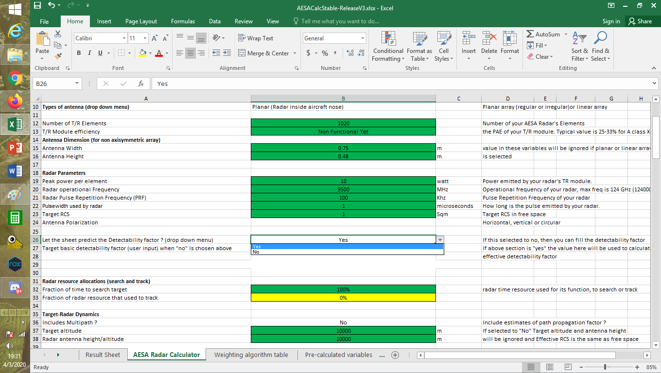
Unlike other calculators, i tried to take account some factors like pulse integration, search sectors, pulsewidth, PRF's etc. Which for some reason not included in others. The most recent iteration i present here can automatically calculate required SNR (Signal to Noise Ratio) required for 90% detection probability of Swerling 1/2 target. Representative for maneuvering fighter aircraft.
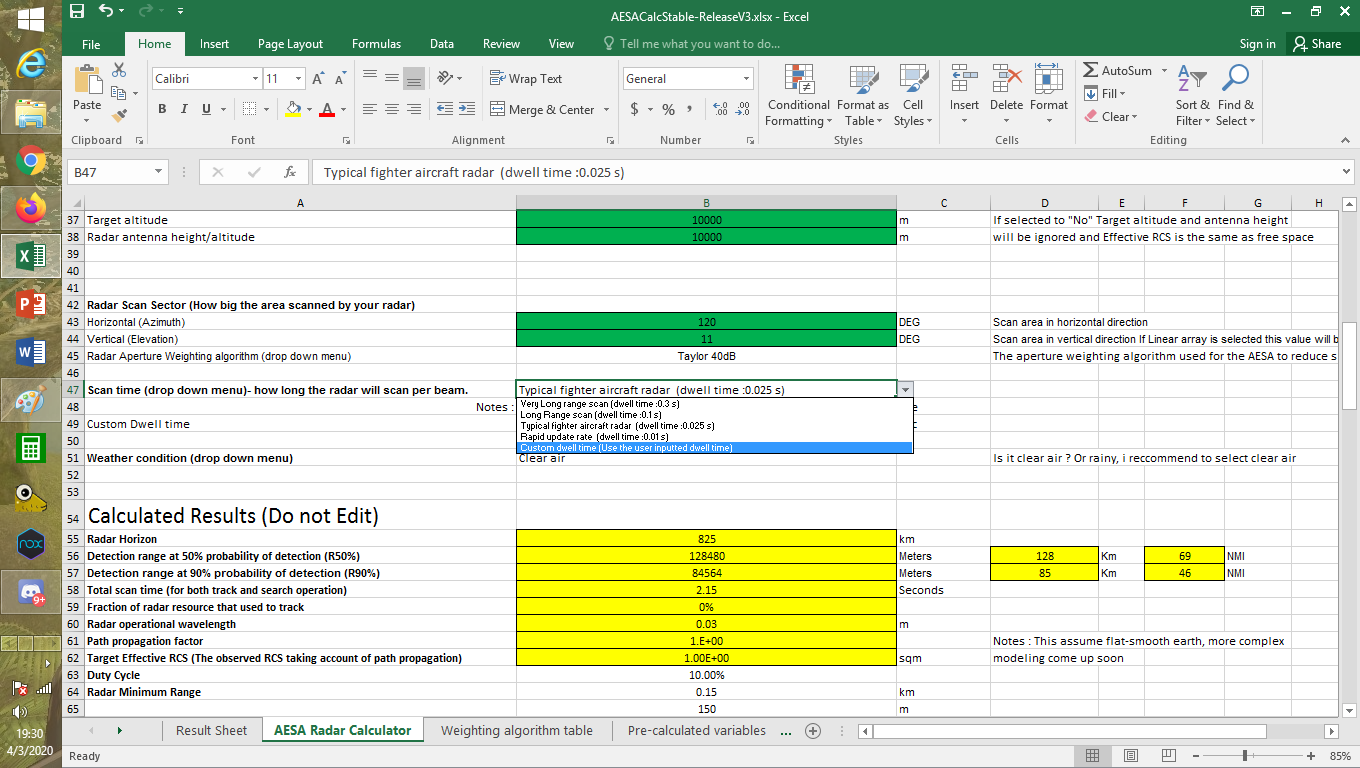
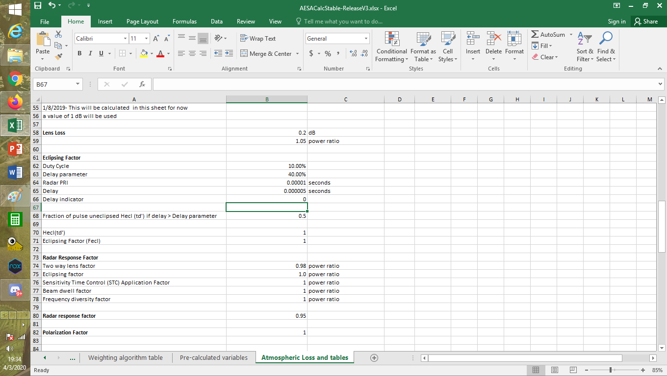
The calculator also take account of the Aperture weighting algorithm. As we know ESA radar or even Slotted planar array radar radiator element arrangement does follow specific mathematically defined weighting scheme to shape its radiation pattern. The purpose of such arrangement is to reduce sidelobe which would be beneficial for the electronic warfare and radar signal processing. For now however the effect of aperture weighting only applies on width of the 3dB beamwidth of the radar, aperture efficiency and width of physical aperture the radar might have.
In later iteration i might try to include some Electronic warfare and ESM considerations, like calculating possible detection range of ESM to the radar and its burn through range against commonly used noise jamming. Deception jamming modeling is possible but quite limited to prediction of S/J (Signal to Jammer ratio) as i lack skill to actually model monopulse tracking to predict effect of sophisticated techniques like cross eye.
The following are some screenshots of the calculator :
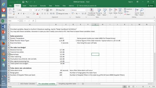
The variables :
Drop down menu containing select-able antenna weighting algorithms
The weighting algorithm table, for now there are only 8 weighting scheme available.
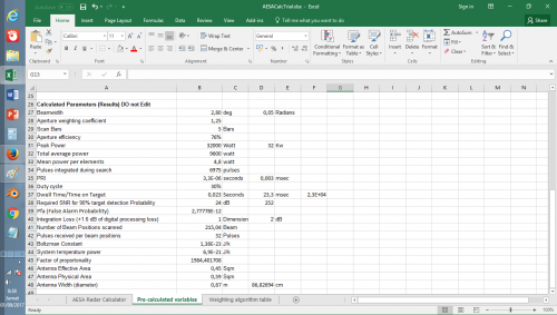
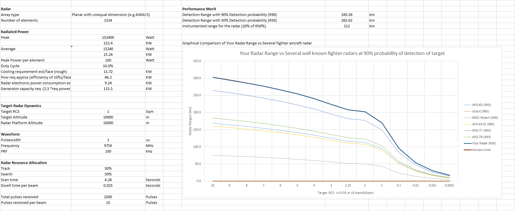
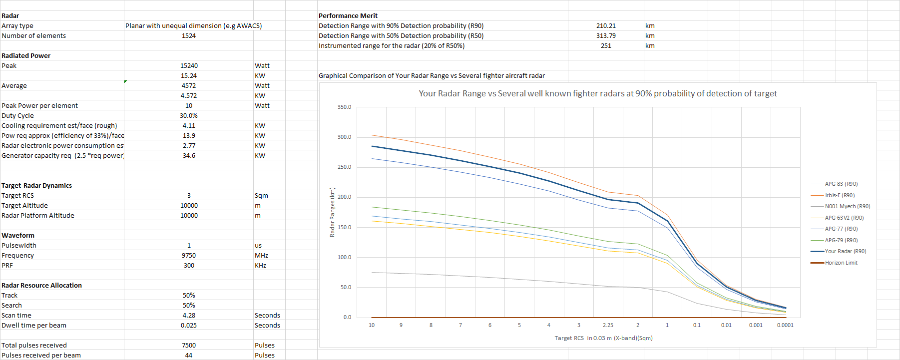
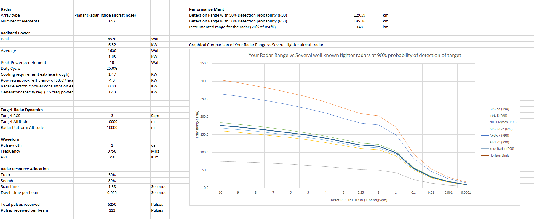
The result coloumn :
As seen there are 2 range predictions. the 50% and 90%.
The detection range at 90% probability states the range where the radar can likely lock-on. Thus engage the target. While at 50% probability is the detection range where the radar have some certainty that the target does exist and may follow up to track and perhaps guide another sensor or wingman to the target.
The spreadsheet can be downloaded through link below :
https://www.secretprojects.co.uk/threads/an-aesa-radar-range-calculator.29367/#post-385925
I am open to any correction or feedback to the excel spreadsheet. and of course, happy using. :-*
Edit :
adding the post where i put the latest version.
Unlike other calculators, i tried to take account some factors like pulse integration, search sectors, pulsewidth, PRF's etc. Which for some reason not included in others. The most recent iteration i present here can automatically calculate required SNR (Signal to Noise Ratio) required for 90% detection probability of Swerling 1/2 target. Representative for maneuvering fighter aircraft.
The calculator also take account of the Aperture weighting algorithm. As we know ESA radar or even Slotted planar array radar radiator element arrangement does follow specific mathematically defined weighting scheme to shape its radiation pattern. The purpose of such arrangement is to reduce sidelobe which would be beneficial for the electronic warfare and radar signal processing. For now however the effect of aperture weighting only applies on width of the 3dB beamwidth of the radar, aperture efficiency and width of physical aperture the radar might have.
In later iteration i might try to include some Electronic warfare and ESM considerations, like calculating possible detection range of ESM to the radar and its burn through range against commonly used noise jamming. Deception jamming modeling is possible but quite limited to prediction of S/J (Signal to Jammer ratio) as i lack skill to actually model monopulse tracking to predict effect of sophisticated techniques like cross eye.
The following are some screenshots of the calculator :
The variables :
Drop down menu containing select-able antenna weighting algorithms
The weighting algorithm table, for now there are only 8 weighting scheme available.
The result coloumn :
As seen there are 2 range predictions. the 50% and 90%.
The detection range at 90% probability states the range where the radar can likely lock-on. Thus engage the target. While at 50% probability is the detection range where the radar have some certainty that the target does exist and may follow up to track and perhaps guide another sensor or wingman to the target.
The spreadsheet can be downloaded through link below :
https://www.secretprojects.co.uk/threads/an-aesa-radar-range-calculator.29367/#post-385925
I am open to any correction or feedback to the excel spreadsheet. and of course, happy using. :-*
Edit :
adding the post where i put the latest version.
Last edited:
") , IOC ~2024.
, IOC ~2024.