Aerospace Trainer Concept Design

Dynoman

ACCESS: Top Secret
Senior Member
Joined
29 July 2009
Messages
1,518
Reaction score
1,512
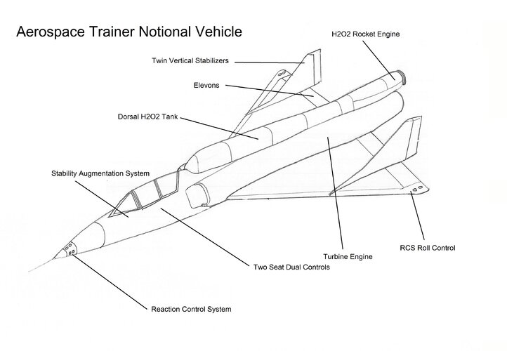
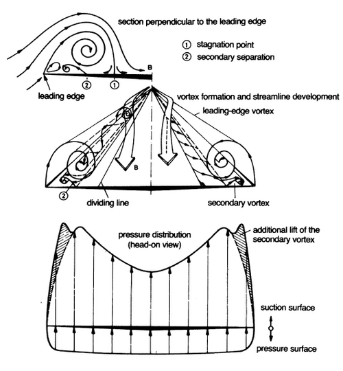
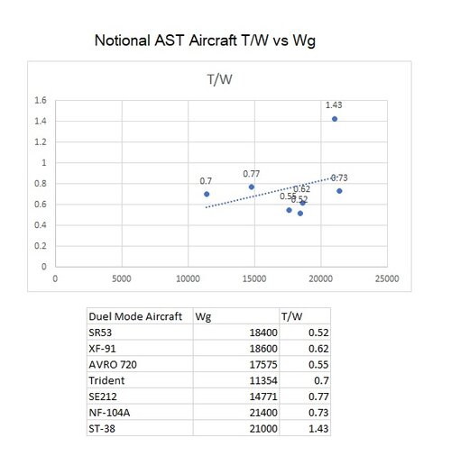
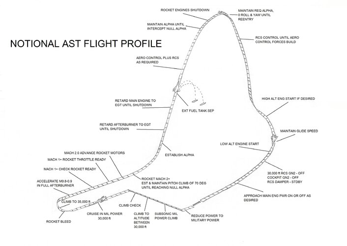
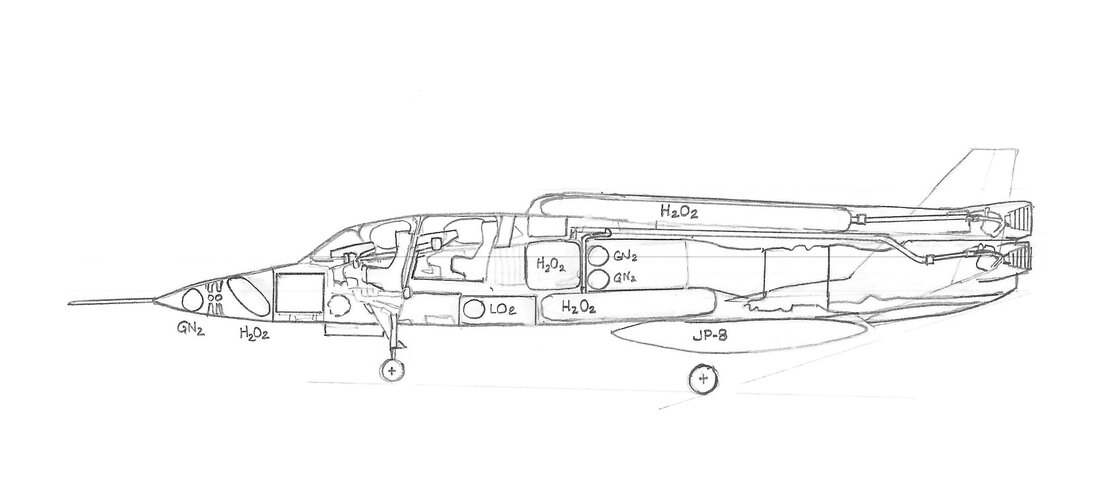
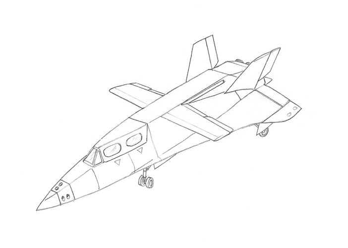
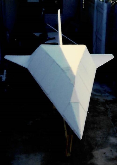
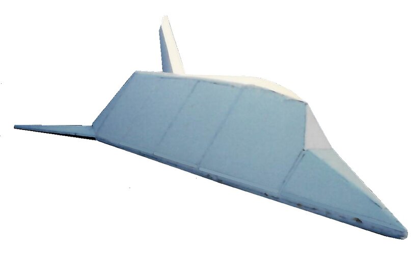
Looking at Spaceship One, Spaceship Two, Dream Chaser, XCOR Lynx, and the NF-104A I thought that it would be interesting to create a general specification for an aerospace rocket trainer with the capability to fly between 120,000 to 360,000 ft. that could be used by space tourism companies for training, lower-cost space experiences, or marketed towards test pilot schools (i.e. USAF TPS, USN TPS, Empire TPS, EPNER, and Fedotov TPS). The design would allow pilots to build up to the altitudes, speeds, and piloting skills using reaction controls systems in a parabolic trajectory.

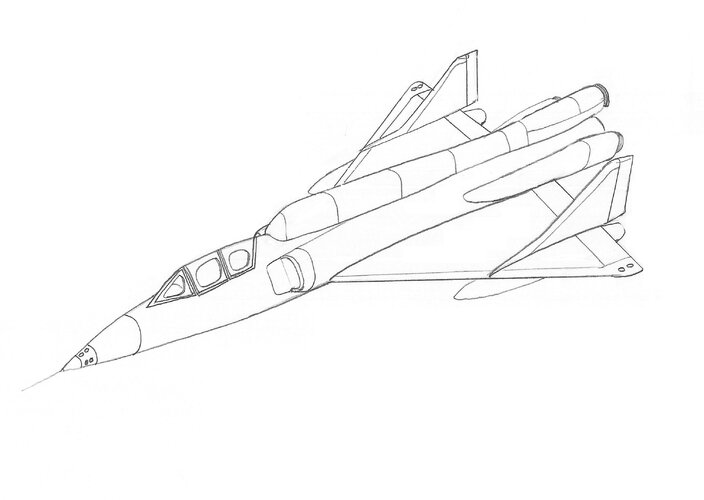
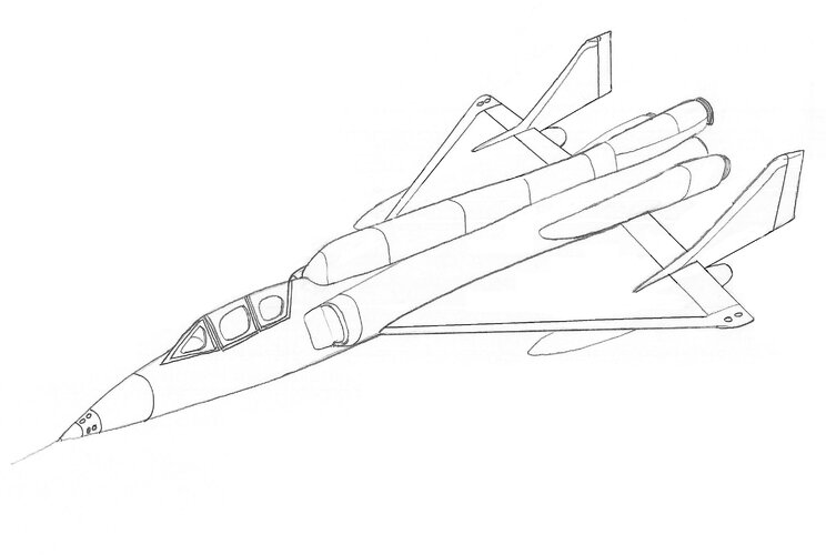
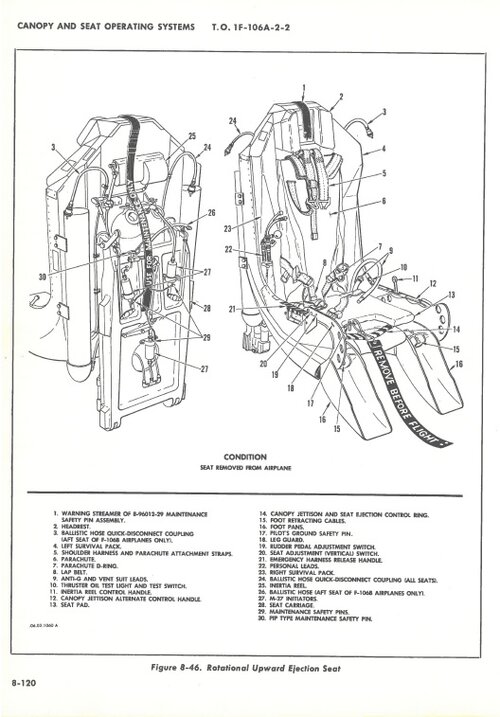
The drawing below is for a notional design using a Convair F-106B whose performance previously allowed it to fly Mach 2.3 with a J-75 (24,500 lb st thrust) engine.
 

Attachments

  • AST.jpg
    AST.jpg
    672 KB · Views: 108
Hé hé hé... (maniacal laugh) I have a bunch of Pdfs on my HD, related to the NF-104A and how it could be brought back - to fly far, far higher than its 1963 record of near 122 000 ft.

Here we gooooooo !
 

Attachments

  • AIAA-2001-3838_History_of_RMI_Super_Performance_90_Percent_H2O2-Kerosene_LR-40_RE-pitch.pdf
    381.3 KB · Views: 28
  • AIAA-2005_3537_Boom_and_Zoom_History_of_NF-104A AST.pdf
    1.8 MB · Views: 24
  • AIAA-2007-5839_Rocket_Starflyer-Modified_NF-104_for_Space_Tourism.pdf
    601.7 KB · Views: 27
  • AR-2-3.pdf
    3.5 MB · Views: 27
Last edited:
Great information! I have one of those documents, the others are awesome! Thanks

I always thought a two seat side-by-side arrangement would aid in Crew Resource Management and add to more efficient training. However, the drag associated with this arrangement maybe excessive. The propulsion requirement to fly twice as high as the NF-104A will require a unit that is more powerful than the original AR-2-3.with 6,600 lb thrust.

A flight profile similar to the NF-104A would be ideal. Departing under turbine power and accelerating to maximum Mach for the design and then igniting the rocket(s) to climb to altitude and then gliding to a horizontal landing either with or without power.

Advancements in flight controls, energy management/navigation systems, SAS system, materials, etc., make the design of a new AST platform an interesting challenging.
 
After reading about the F-106 flying Mach 2.3 and the windows deforming and the paint melting under the heat load, I modified the windows and added steel nose cone and leading edges. Also I added three AR-2-3 type engines to give a combined rocket thrust of 19,800 lb thrust force. It includes two external tanks of hydrogen peroxide. The aircraft's estimated weight is 30,000-35,000 lbs.
 

Attachments

  • Three Rocket Design.jpg
    Three Rocket Design.jpg
    465.6 KB · Views: 59
Last edited:
Delta create lift with the help of a spanwise vortex. With your verticals in the middle of the extrados, you'll probably kill lift in the outboard sections and generate a lot of drag with all the airstream vector change (turning from being spanwise to chordwise). See how similar design have their fins pushed out on booms.

f6336f982044a0d181afff64efef5dc7530293a0.jpg
 
Modified the sketch to reflect the repositioned vertical stabilizers.
 

Attachments

  • Three Rocket Design2.jpg
    Three Rocket Design2.jpg
    464.3 KB · Views: 38
Great information! I have one of those documents, the others are awesome! Thanks

I always thought a two seat side-by-side arrangement would aid in Crew Resource Management and add to more efficient training. However, the drag associated with this arrangement maybe excessive. The propulsion requirement to fly twice as high as the NF-104A will require a unit that is more powerful than the original AR-2-3.with 6,600 lb thrust.

A flight profile similar to the NF-104A would be ideal. Departing under turbine power and accelerating to maximum Mach for the design and then igniting the rocket(s) to climb to altitude and then gliding to a horizontal landing either with or without power.

Advancements in flight controls, energy management/navigation systems, SAS system, materials, etc., make the design of a new AST platform an interesting challenging.

Silly me, how could I forgot that one ?

NF-104A was CL-586. From there were only two atempts at improved variants: the above CL-772 and the CL-747.

CL-747 was essentially a TF-104G with the NF-104A rocket stuck in the tail. CL-772 as you can see was far more ambitious albeit perhaps making less sense (J85 in place of J79 ? sure, much more room for rocket props, but also a weaker jet engine)

CL-747 just made so much sense. Because, you see, with a second seat they could have carried a suborbital space tourist looong before Jeff Bezos or Richard Branson (50 years before and counting !)

Imagine: suborbital tourism flights right off 1965, using a barely modified TF-104G. Now that would have been something. And don't forget the German (T)F-104G production line only shut down in 1972 while the italian (T)F-104S shut down in 1979.

Next step, swaps that unstable and dangerous H2O2 oxidizer for much gentler N2O (= swaps bleach for laughing gas !) and you have a suborbital space tourism vehicle straight out of a runway and straight out of the 1970's.

Would have been completely awesome. And in my TL "Dark Moon rising" it happens as a "consolation prize" in 1972 for astronauts after the Shuttle gets canned by Nixon OMB bean counters...
 
Archibald, more incredible info!

The CL-747 was dual mode using the J-79 to get to 35,000ft and M2.1 then combined using the AR2-3 to propel the aircraft upwards of 120,000ft.

The CL-772 may have relied on the J-85 to get airborne or possibly as a recovery engine in the event that the CL-772 arrives short of its landing area. I assume it was not ground launched from a gantry.

Northrop's N-205 ST-38 planned to use three 10,000 lb rocket motors using JP-5 and peroxide. Northrop's vehicle would be ground launched from a rail and reach 90,000 ft at rocket propellant burnout, traveling at M3.2. ST-38 was planned to reach 200,000 ft. from a liftoff weight of 21,000 lb.

Do you know the thrust of the Rocketdyne AR-4?
The SPF link below says the ST-38 used AR-4's at 10,000 lb thrust each.

Also, the notional vehicle, based on the Convair F-106B, may be too heavy, weighing in the 30,000-40,000lb range. The NF-104A weighed 21,000 lb and the N-205 was also expected to weigh 21,000 lb.
 
Last edited:
Delta create lift with the help of a spanwise vortex. With your verticals in the middle of the extrados, you'll probably kill lift in the outboard sections and generate a lot of drag with all the airstream vector change (turning from being spanwise to chordwise). See how similar design have their fins pushed out on booms.

f6336f982044a0d181afff64efef5dc7530293a0.jpg
Deltas lift conventionally at shallow angles of attack.
OTOH at steep angles of attack, vortices generated by the swept leading edge generate most of the lift. Those vortices also generate huge amounts of drag, so high A. of A. flight is really only relevant on deltas with massive reserves of power (think jet fighters with after-burners).
In this case, I suspect that they moved the vertical fins to booms in order to mount them farther aft. Increasing the length of the tail moment arm improves both yaw stability and yaw control.
 
I think that the idea of moving them behind the TE is that the vortex flow along the LE, which helps to maintain laminar flow by energizing the turbulent eddies that form as the flow separates with increasing AoA, would be disrupted by the wing mounted stabilizers and fences. My thought process was that the fences and stabilizer would reduce spanwise flow (similar to MiG-21 or MiG-29) and channel the flow field over the flight control surfaces. However, I can see how the lift distribution across the delta wing would be affected if there were a fence in the way.
 

Attachments

  • Vortex on Delta Wing.png
    Vortex on Delta Wing.png
    39.9 KB · Views: 41
Yes dear Dynoman,
Barnaby Wainfain experimented with dozens of different fin configurations before he built his Facetmobile prototype. RC modellers have built and flown dozens more variants on the Facetmobile concept. Wainfain soon concluded that center-line fins (s) are good and tip fins are good, but any fins partway out the wings interfered with vortices. It seems that really low aspect ratio wings benefit from vortices colliding along the center-line and cancelling each other. When vortices collide, they vastly reduce drag.

MR. Wainfian is continuing the Facetmobile project by assisting EAA Chapter 292 in Independence Oregon build a batch of 6 single-seater FMX-4 Facetmobiles while also building a two-seater prototype. By September of 2021, they taxi-tested an uncovered FMX-4.
 
Riggerrob, that's awesome that they are rebuilding the Facetmobile and developing it further. I always thought that it was an interesting design. Looked like a poor-man's stealth fighter. Very cool! :cool:
 
Tangential, 'Facetmobile' reminds me of a famous (*) one-class sailing dinghy design which used ply sheets, either flat / as-is, or with a 'simple' curve. Not a 'compound' curve aboard. Literally thousands were built in enthusiasts' sheds and garages...

*) Not so famous that I remember name...
 
A quick look at the T/W versus Gross Weight of mixed propulsion aircraft (Turbine/Rocket) aircraft. The average T/W is 0.76 and gross weight is 17,586 lbs. The ST-38 (N-205) is the best performer with three AR-4s and the light airframe of the T-38 with a T/W of 1.43. The notional AST F-106B weighs 35,000 lbs with three AR-4s (30,000 lbs) and its afterburning J-75 (24,500 lb thrust) providing a T/W of 1.56.
 

Attachments

  • AST T to W.jpg
    AST T to W.jpg
    53.1 KB · Views: 35
Last edited:
It completely blew my mind the T-38, just like the F-104, had a suborbital trainer rocket variant & project. But there is not a lot of room inside a T-38 to cram rocket fuel tanks.
 
I agree. The notional design here was drawn with two external tanks that I was considering would be dropped during the rocket boost phase. These tanks would carry either the JP fuel needed for the J-75 if more internal fuel was needed for the hydrogen peroxide or the H2O2 if the rocket burntime needed to be longer.
 
Notional AST flight profile based on phases of the NF-104A profile.
 

Attachments

  • Notional AST FLT Profile.jpg
    Notional AST FLT Profile.jpg
    747.5 KB · Views: 38
F-106B cockpit with rotational ejection seats.
 

Attachments

  • Ejection Seats F-106B.jpg
    Ejection Seats F-106B.jpg
    139.9 KB · Views: 34
  • Rotational Ejection Seat.jpg
    Rotational Ejection Seat.jpg
    114.3 KB · Views: 38
Let's not forget that the T-38 couldn't do Mach 2 at 60k+. Hence it had to climb on its rocket instead of converting kinetics to potential energies.

I fear that some are only looking at the Rocket mass fraction forgetting that, mass wise (and cost-wise, especially for repeated operations), burning JP-7 was immensely more efficient than rocket's combustion...

So, @Dynoman, you would probably do better keeping those EFT filled with classical fuel.
 
Its an interesting problem. Typically mass fractions for aircraft are based on range using the Brequet equation. However, the typical range of fighter aircraft of the era were 500 nm combat range and 2000 nm ferry range. Northop's AST ST-38 mission range is 80 miles. The NF-104A would have been even shorter.
TomcatViP, hopefully the EFT can be eliminated as we go. I am not sure what the internal volume is required for the H2O2. We'll know more hopefully after looking at the weight and fuel fractions required.

Here are the proposed mission segments for the weight fraction estimates.
 

Attachments

  • Notional AST FLT Profile Fuel Fractions.jpg
    Notional AST FLT Profile Fuel Fractions.jpg
    895.1 KB · Views: 41
Last edited:
Typical mission fractions for Takeoff, Climb, Decent, and Approach (0.98, 0.97, 0.99, and 0.997, respectively) can be used here for a first estimate.
 
My two cents: empty EFT before accelerating to Mach 2. That way, time to Mach 2 will be lower. Excess fuel could then be discarded from the mission design profile and a better mass fraction could be allocated for rocket propulsion integration etc...

Nice graphics by the way!
 
If you want to 'rocket' to high altitude, lose the big delta wing. Use pop-out glide-wings, like an SDB-bomb, at low altitudes. Three rigid fins in back for stability. Three frontal stubby - but minimal size - canards for full axis control. Use the glide wing to get to altitude. Use the minimal and most efficient afterburning turbofan available to get to your target launch altitude. Let the rocket rip as you nose-up then retract your glide-wing. Get to the apogee and open that glide-wing. Use an optimal glide angle on the way down.
 
MadRat, I like the idea of a dedicated design. The original idea was to modify an existing design that had proven high speed performance and examine the modifications necessary to meet the mission requirement of reaching 120,000 to 360,000 ft. A design similar to McDonnell Douglas Model 176 or CL-639 with retractable turbine engines or a retractable inlet would be interesting. I added a profile sketch of the notional design.
 

Attachments

  • Model 176.png
    Model 176.png
    35.8 KB · Views: 42
  • CL-639.gif
    CL-639.gif
    71 KB · Views: 47
  • Possible Internal Tank Config.jpg
    Possible Internal Tank Config.jpg
    295 KB · Views: 55
Last edited:
Here's a concept based on the Model 176. Two seat in tandem, VG wings, four AR-4 rocket engines. Ground launched. Possibly from a rail with external tank and or boosters/RATO. Of course not as cost effective as a modified high altitude/high speed fighter design, but enables crews to experience the boost phase of the launch profile and allows for crews to train for boost phase guidance failures (i.e. manually controlled boost). Which a Dyna Soar astronaut experimented with in simulation (http://web.mit.edu/digitalapollo/Documents/Chapter4/x20control.pdf).
 

Attachments

  • Concept AST Two Seat Tandem.jpg
    Concept AST Two Seat Tandem.jpg
    285.1 KB · Views: 59
Last edited:
Configuration is similar to a free-flight faceted glider design I worked on as a college student years ago.
 

Attachments

  • Student Project1.jpg
    Student Project1.jpg
    76.3 KB · Views: 39
  • Quarter View SP.jpg
    Quarter View SP.jpg
    49.6 KB · Views: 24
Back
Top Bottom