
You are using an out of date browser. It may not display this or other websites correctly.
You should upgrade or use an alternative browser.
You should upgrade or use an alternative browser.
Soviet / Russian RWR (Sirena, Beryoza, Pastel)
Thank you for the information, but do you have any picture of how the display look like?
''Russian Navy Su-33 Sea Flanker. Cockpit Upgrade with SPO-32 Pastel (L-150) RWR.''
View: https://x.com/StefanKnippsch3/status/1483576300174712837
On the pic we can see SPO-32 'Pastel''s screen.

After the Su-25T/TM and Su-33 ,five serial Su-30's got SPO-32 also and after them ,all new Russian fighters got SPO-32 but the data from the RWR was presented on the new multifunctional MFD/LCD.
SPO-15 (L006) on the Su-27SK, from Technical Manual
Some details from the 'Flight Manual for the Su-27SK' ( pages 117,118,119 and 120).
САМОЛЕТ СУ-27СК
РУКОВОДСТВО ПО ЛЕТНОЙ ЭКСПЛУАТАЦИИ
РУКОВОДСТВО ПО ЛЕТНОЙ ЭКСПЛУАТАЦИИ
Станция предупреждения об облучении самолёта СПО-15ЛМ.
Станция предназначена для выдачи информации лётчику об облучении самолёта, определения направления на облучающее средство, его типа и режима работы.
Станция обеспечивает:
обнаружение облучения самолёта РЛС зенитно-ракетных комплексов (ЗРК), зенитно-стрелковых комплексов (ЗСК) и бортовыми РЛС истребителей-перехватчиков в следующих секторах:
а) по азимуту ± 90° в ЗПС и ППС – при облучении РЛС большой мощности или на малых дальностях от них, и не менее ± 70° – на средних и больших дальностях;
б) по углу места не менее ± 30° в ЗПС и ППС;
определение направления на облучающую РЛС с точностью ± 10° в секторе ± 40°, а в остальной зоне с точностью до 40° в ППС и до 45° – в ЗПС;
определение типа облучающей РЛС (по виду излучения) и режима работы РЛС («обзор», «сопровождение»);
определение наиболее опасной РЛС и выделение её в качестве главного атакующего средства (выбор главной цели);
определение динамики сближения или удаления с главным атакующим средством.
Станция обеспечивает обнаружение облучающих РЛС и выдачу информации о них на дальности не менее 120 % от дальности действия оружия атакующего средства.
Полученная информация выдаётся на индикатор (рис. 38), расположенный на приборной доске лётчика.
На шкалах пеленга (внутренней – зелёные круглые метки, внешней – жёлтые оцифрованные метки в ППС и жёлтые треугольные метки в ЗПС) индицируется истинное положение цели по азимуту относительно силуэта самолёта.
Индикация азимута цели осуществляется высвечиванием зелёной метки пеленга на внутренней шкале.
Индикация главной цели осуществляется одновременным высвечиванием зеленой метки на внутренней шкале и жёлтой оцифрованной метки на внешней шкале.
Индикация типа облучающего средства осуществляется высвечиванием метки с обозначением:
П – облучение ЗРК «Терьер» или самолетами типа F-4, F-104 с одновременным включением подсвета для наведения ракет типа «Спарроу»;
З – облучение ЗРК типа «Чапарел», «Вулкан» или ЗРК «Сивульф»;
X – облучение ЗРК типа «Хок» или самолетами F-14, F-15, F-16 и F-18 (с больших дальностей);
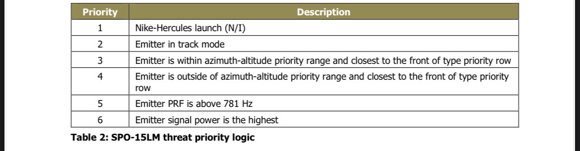
Н – облучение ЗРК типа «Найк-Геркулес», «Патриот», «Талос»;
F – облучение с малых дальностей самолета F-14, F-15, F-16 и F-18 или ракетой «Феникс» с РТС (возможно высвечивание сигнала Г совместно с сигналом X);
С – облучение самолетами типа F-4, F-5, F-104, F-111 (без включения канала подсвета), МИРАЖ, ЯГУАР, ЛАЙТНИНГ или ЗРК типа "Терьер", "Кроталь",
Индикация о типе цели осуществляется высвечиванием метки зеленого цвета на шкале типов. Индикация о главном типе осуществляется высвечиванием дополнительной метки жёлтого цвета над меткой типа.
Индикация динамики сближения с РЛС осуществляется высвечиванием меток на шкале градации мощности. Чем ближе самолет будет подлетать к РЛС, тем больше число меток подсвечивается одновременно (метки нарастают против часовой стрелки).
Индикация динамики сближения самолета с атакующей ракетой осуществляется миганием движущейся метки градации мощности. Метка ракеты движется по часовой стрелке, (поочередно начинают мигать и гаснуть метки градации мощности). Начало движения метки соответствует расчетному пуску ракеты, определяемому самой ракетой.
Индикация границы зоны поражения главным атакующим средством осуществляется миганием одной из меток на шкале градации мощности.
Индикация о режиме работы СОПРОВОЖДЕНИЕ главного типа осуществляется высвечиванием метки ЗАХВАТ красного цвета в центре индикатора (в режиме ОБЗОР метка не высвечивается). В наиболее опасной ситуации (при приближении ракеты к самолёту) метка ЗАХВАТ периодически мигает.
Индикация о режиме работы РЛС неглавных типов осуществляется постоянным высвечиванием метки неглавного пеленга и типа в режиме сопровождения и мигания с периодом обзора при работе РЛС в режиме обзора.
Индикация об относительном положении облучающей РЛС в вертикальной плоскости осуществляется высвечиванием жёлтых меток В (верх) или Н (низ), расположенных в центре индикатора.
При облучении самолета под углом ± 15° относительно самолета загорание меток В и Н не указывает однозначно направление приема в указанных углах, вследствие чего допускается загорание метки В на индикаторе при облучении снизу или одновременное загорание обеих меток.
Одновременно со световой индикацией в шлемофон выдается прерывистый звуковой сигнал низкой тональности при облучении РЛС, работающей в режиме ОБЗОР, или непрерывный звуковой сигнал высокой тональности – в режиме СОПРОВОЖДЕНИЕ.
Громкость звучания звукового сигнала регулируется регулятором ЗВУК. При отключении звуковой сигнализации на индикаторе высвечивается табло ЗВУК ОТКЛ.
Перед полётом для проверки исправности Л006ЛМ необходимо:
на пульте управления станций установить переключатели:
ОБЗОР – в верхнее положение,
ВЫСОТА-ТИП – в положение 1,5;
ДИАПАЗОН I, II - АВТОМАТ – в положение ДИАПАЗОН I, II;
установить выключатель СУО ОБОРОНА на щитке питания в верхнее положение, при этом загорается метка сигнал исправности на индикаторе;
через 2-3 минуты нажать переключатель КОНТР на индикаторе в положение АВТ, при этом должны высветиться все метки на индикаторе, а метка сигнализации исправности погаснуть и вновь загореться через 3-5 сек при исправной станции;
после загорания метки сигнализации исправности отпустить переключатель КОНТР;
При случайном нажатии переключателя КОНТР в положение РУЧН (на индикаторе гаснет метка сигнализации исправности) для восстановления работоспособности станции кратковременно установить его в положение АВТ;
установить выключатель СУО ОБОРОНА в нижнее положение.
В полёте выделение типа главной РЛС противника осуществляется в автоматическом или ручном режиме.
Для автоматического выделения главной РЛС необходимо переключателем ВЫСОТА-ТИП установить высоту полёта в одно из положений 1, 5, 8, 16, 30, а переключатель АВТОМАТ-ДИАПАЗОН I, II – установить в положение ДИАПАЗОН I, II (положение АВТОМАТ используется при наличии устройств сопряжения станции СПО-15 с аппаратурой РЭБ).
При подходе к зоне боевых действий включить выключатель СУО ОБОРОНА. При полёте самолёта в зоне действия РЛС и совершении маневра с креном более 15° на индикаторе могут кратковременно индицироваться 3-4 главных пеленга. Направление на облучающую РЛС в этом случае определяется по среднему главному пеленгу при индицировании 3-х главных пеленгов и по двум средним главным пеленгам при индицировании 4-х главных пеленгов.
Высвечивание меток пеленгов 10° и 30° (слева и справа относительно контура самолёта на индикаторе) соответствует облучению самолета с указанных направлений, а высвечивание метки 50° – облучению самолета под углом 50°-85° слева или справа с передней полусферы.
Одновременное высвечивание меток пеленга 90° и 50° слева или справа свидетельствует об облучении самолёта со стороны 85° - 95° соответствующего направления на малых дальностях от РЛС (на большое дальностях метка 90° не высвечивается и возможно пропадание индикации).
Высвечивание только левой (правой) метки сектора задней полусферы свидетельствует об облучении самолета с соответствующего направления задней полусферы.
Управление индикацией в режиме работы облучающих средств производится с помощью выключателя ОБЗОР. В положении ОБЗОР на индикатор выдается информация о всех РЛС, работающих в зоне приема, в отключенном положении (в нижнем положении) – на индикатор выдается информация только об РЛС, работающих в режиме СОПРОВОЖДЕНИЕ (за исключением станций, работающих в режиме СОПРОВОЖДЕНИЕ НА ПРОХОДЕ).
ПРЕДУПРЕЖДЕНИЕ:
1.Режим работы БРЛС квазинепрерывного излучения, работающих в режиме СОПРОВОЖДЕНИЕ НА ПРОХОДЕ не определяется (метка ЗАХВАТ не индицируется).
2. При облучении бортовыми РЛС квазинепрерывного излучения самолетов F-14, F-15, F-16, F-18 и ЗРК «Патриот» на больших и средних дальностях (до 5 градаций мощности) главным индицируется метка типа «Х» в мигающем режиме. На малых дальностях главным индицируется метка типа «F» с одновременным погасанием метки типа «Х» и уменьшением количества градации мощности с последующим их нарастанием.
Для ручного выделения главной РЛС необходимо переключатель ВЫСОТА-ТИП установить в положение интересующей РЛС (П, З, Х, Н, F, С), при этом на индикаторе станции индуцируется выбранная РЛС как главная. Индикация нетиповых целей может быть отключена установкой переключателя ВЫСОТА-ТИП в крайнее правое положение.
Используя информацию, определить тип атакующего средства, направление атаки и режим работы, принять решение на выполнение маневра для срыва захвата атакующего средства или применение помех.
При одновременной работе РЛПК и Л006ЛМ возможно индицирование ложной информации на индикаторе Л006ЛМ (высвечивание меток пеленгов 10, 30, 50, 90 слева и справа, типа X, градации мощности до 8, метки В, Н и ЗАХВАТ).
Для определения фактической обстановки необходимо (при возможности) на этапах поиска и обнаружения цели переключатель ИЗЛУЧ-ЭКВ-ОТКЛ на щитке управления РЛПК установить на 5-10 сек в положение ОТКЛ.
На работу Л006ЛМ оказывает влияние работа на излучение аппаратуры САП (изд. Л203ИЭ) – высвечиванием на индикаторе Л006ЛМ ложной информации (типы X и F, 90°,30°,10° неглавный слева, 50° главный слева, «низ», «захват», 12 градаций мощности, левый задний сектор).
ПРЕДУПРЕЖДЕНИЕ.
При работе аппаратуры изд.Л203ИЭ на излучение информацией высвечиваемой на индикаторе Л006ЛМ не пользоваться.
После выполнения задания отключить станцию.
Transl :
Aircraft radiation warning station/RWR SPO-15LM.Индикация азимута цели осуществляется высвечиванием зелёной метки пеленга на внутренней шкале.
Индикация главной цели осуществляется одновременным высвечиванием зеленой метки на внутренней шкале и жёлтой оцифрованной метки на внешней шкале.
Индикация типа облучающего средства осуществляется высвечиванием метки с обозначением:
П – облучение ЗРК «Терьер» или самолетами типа F-4, F-104 с одновременным включением подсвета для наведения ракет типа «Спарроу»;
З – облучение ЗРК типа «Чапарел», «Вулкан» или ЗРК «Сивульф»;
X – облучение ЗРК типа «Хок» или самолетами F-14, F-15, F-16 и F-18 (с больших дальностей);
Н – облучение ЗРК типа «Найк-Геркулес», «Патриот», «Талос»;
F – облучение с малых дальностей самолета F-14, F-15, F-16 и F-18 или ракетой «Феникс» с РТС (возможно высвечивание сигнала Г совместно с сигналом X);
С – облучение самолетами типа F-4, F-5, F-104, F-111 (без включения канала подсвета), МИРАЖ, ЯГУАР, ЛАЙТНИНГ или ЗРК типа "Терьер", "Кроталь",
Индикация о типе цели осуществляется высвечиванием метки зеленого цвета на шкале типов. Индикация о главном типе осуществляется высвечиванием дополнительной метки жёлтого цвета над меткой типа.
Индикация динамики сближения с РЛС осуществляется высвечиванием меток на шкале градации мощности. Чем ближе самолет будет подлетать к РЛС, тем больше число меток подсвечивается одновременно (метки нарастают против часовой стрелки).
Индикация динамики сближения самолета с атакующей ракетой осуществляется миганием движущейся метки градации мощности. Метка ракеты движется по часовой стрелке, (поочередно начинают мигать и гаснуть метки градации мощности). Начало движения метки соответствует расчетному пуску ракеты, определяемому самой ракетой.
Индикация границы зоны поражения главным атакующим средством осуществляется миганием одной из меток на шкале градации мощности.
Индикация о режиме работы СОПРОВОЖДЕНИЕ главного типа осуществляется высвечиванием метки ЗАХВАТ красного цвета в центре индикатора (в режиме ОБЗОР метка не высвечивается). В наиболее опасной ситуации (при приближении ракеты к самолёту) метка ЗАХВАТ периодически мигает.
Индикация о режиме работы РЛС неглавных типов осуществляется постоянным высвечиванием метки неглавного пеленга и типа в режиме сопровождения и мигания с периодом обзора при работе РЛС в режиме обзора.
Индикация об относительном положении облучающей РЛС в вертикальной плоскости осуществляется высвечиванием жёлтых меток В (верх) или Н (низ), расположенных в центре индикатора.
При облучении самолета под углом ± 15° относительно самолета загорание меток В и Н не указывает однозначно направление приема в указанных углах, вследствие чего допускается загорание метки В на индикаторе при облучении снизу или одновременное загорание обеих меток.
Одновременно со световой индикацией в шлемофон выдается прерывистый звуковой сигнал низкой тональности при облучении РЛС, работающей в режиме ОБЗОР, или непрерывный звуковой сигнал высокой тональности – в режиме СОПРОВОЖДЕНИЕ.
Громкость звучания звукового сигнала регулируется регулятором ЗВУК. При отключении звуковой сигнализации на индикаторе высвечивается табло ЗВУК ОТКЛ.
Перед полётом для проверки исправности Л006ЛМ необходимо:
на пульте управления станций установить переключатели:
ОБЗОР – в верхнее положение,
ВЫСОТА-ТИП – в положение 1,5;
ДИАПАЗОН I, II - АВТОМАТ – в положение ДИАПАЗОН I, II;
установить выключатель СУО ОБОРОНА на щитке питания в верхнее положение, при этом загорается метка сигнал исправности на индикаторе;
через 2-3 минуты нажать переключатель КОНТР на индикаторе в положение АВТ, при этом должны высветиться все метки на индикаторе, а метка сигнализации исправности погаснуть и вновь загореться через 3-5 сек при исправной станции;
после загорания метки сигнализации исправности отпустить переключатель КОНТР;
При случайном нажатии переключателя КОНТР в положение РУЧН (на индикаторе гаснет метка сигнализации исправности) для восстановления работоспособности станции кратковременно установить его в положение АВТ;
установить выключатель СУО ОБОРОНА в нижнее положение.
В полёте выделение типа главной РЛС противника осуществляется в автоматическом или ручном режиме.
Для автоматического выделения главной РЛС необходимо переключателем ВЫСОТА-ТИП установить высоту полёта в одно из положений 1, 5, 8, 16, 30, а переключатель АВТОМАТ-ДИАПАЗОН I, II – установить в положение ДИАПАЗОН I, II (положение АВТОМАТ используется при наличии устройств сопряжения станции СПО-15 с аппаратурой РЭБ).
При подходе к зоне боевых действий включить выключатель СУО ОБОРОНА. При полёте самолёта в зоне действия РЛС и совершении маневра с креном более 15° на индикаторе могут кратковременно индицироваться 3-4 главных пеленга. Направление на облучающую РЛС в этом случае определяется по среднему главному пеленгу при индицировании 3-х главных пеленгов и по двум средним главным пеленгам при индицировании 4-х главных пеленгов.
Высвечивание меток пеленгов 10° и 30° (слева и справа относительно контура самолёта на индикаторе) соответствует облучению самолета с указанных направлений, а высвечивание метки 50° – облучению самолета под углом 50°-85° слева или справа с передней полусферы.
Одновременное высвечивание меток пеленга 90° и 50° слева или справа свидетельствует об облучении самолёта со стороны 85° - 95° соответствующего направления на малых дальностях от РЛС (на большое дальностях метка 90° не высвечивается и возможно пропадание индикации).
Высвечивание только левой (правой) метки сектора задней полусферы свидетельствует об облучении самолета с соответствующего направления задней полусферы.
Управление индикацией в режиме работы облучающих средств производится с помощью выключателя ОБЗОР. В положении ОБЗОР на индикатор выдается информация о всех РЛС, работающих в зоне приема, в отключенном положении (в нижнем положении) – на индикатор выдается информация только об РЛС, работающих в режиме СОПРОВОЖДЕНИЕ (за исключением станций, работающих в режиме СОПРОВОЖДЕНИЕ НА ПРОХОДЕ).
ПРЕДУПРЕЖДЕНИЕ:
1.Режим работы БРЛС квазинепрерывного излучения, работающих в режиме СОПРОВОЖДЕНИЕ НА ПРОХОДЕ не определяется (метка ЗАХВАТ не индицируется).
2. При облучении бортовыми РЛС квазинепрерывного излучения самолетов F-14, F-15, F-16, F-18 и ЗРК «Патриот» на больших и средних дальностях (до 5 градаций мощности) главным индицируется метка типа «Х» в мигающем режиме. На малых дальностях главным индицируется метка типа «F» с одновременным погасанием метки типа «Х» и уменьшением количества градации мощности с последующим их нарастанием.
Для ручного выделения главной РЛС необходимо переключатель ВЫСОТА-ТИП установить в положение интересующей РЛС (П, З, Х, Н, F, С), при этом на индикаторе станции индуцируется выбранная РЛС как главная. Индикация нетиповых целей может быть отключена установкой переключателя ВЫСОТА-ТИП в крайнее правое положение.
Используя информацию, определить тип атакующего средства, направление атаки и режим работы, принять решение на выполнение маневра для срыва захвата атакующего средства или применение помех.
При одновременной работе РЛПК и Л006ЛМ возможно индицирование ложной информации на индикаторе Л006ЛМ (высвечивание меток пеленгов 10, 30, 50, 90 слева и справа, типа X, градации мощности до 8, метки В, Н и ЗАХВАТ).
Для определения фактической обстановки необходимо (при возможности) на этапах поиска и обнаружения цели переключатель ИЗЛУЧ-ЭКВ-ОТКЛ на щитке управления РЛПК установить на 5-10 сек в положение ОТКЛ.
На работу Л006ЛМ оказывает влияние работа на излучение аппаратуры САП (изд. Л203ИЭ) – высвечиванием на индикаторе Л006ЛМ ложной информации (типы X и F, 90°,30°,10° неглавный слева, 50° главный слева, «низ», «захват», 12 градаций мощности, левый задний сектор).
ПРЕДУПРЕЖДЕНИЕ.
При работе аппаратуры изд.Л203ИЭ на излучение информацией высвечиваемой на индикаторе Л006ЛМ не пользоваться.
После выполнения задания отключить станцию.
Transl :
The station is designed to provide information to the pilot about the irradiation of the aircraft, to determine the direction of the irradiating agent, its type and operating mode.
The station provides:
detection of aircraft irradiation by radars of anti-aircraft missile systems (SAM), anti-aircraft rifle systems (ZSK) and on-board radars of fighter-interceptors in the following sectors:
a) in azimuth ± 90° in the rear hemipshere /ZPS and front hemisphere/PPS - when irradiated by high-power radars or at short distances from them, and not less than ± 70° - at medium and long distances;
b) by elevation angle of not less than ± 30° in the ZPS and PPS;determination of the direction to the irradiating radar with an accuracy of ± 10° in the sector of ± 40°, and in the remaining zone with an accuracy of up to 40° in the PPS and up to 45° in the ZPS;
determining the type of irradiating radar (by type of radiation) and the radar operating mode ("search", "tracking"); determining the most dangerous radar and identifying it as the main attack vehicle (selecting the main target); determining the dynamics of approaching or moving away from the main attack vehicle.
The station provides detection of irradiating radars and the provision of information about them at a range of at least 120% of the range of the attacking vehicle’s weapons.
The information received is displayed on the indicator (Fig. 38) located on the pilot's instrument panel.
The bearing scales (inner - green round marks, outer - yellow digitized marks in the PPS and yellow triangular marks in the ZPS) indicate the true position of the target in azimuth relative to the aircraft silhouette.
The target azimuth is indicated by the green bearing mark on the inner scale.The main target is indicated by the simultaneous illumination of the green mark on the inner scale and the yellow digitized mark on the outer scale.
The type of irradiating agent is indicated by the illumination of a label with the designation:P – irradiation by the Terrier SAM system or by F-4, F-104 type aircraft with simultaneous activation of illumination for guiding Sparrow type missiles;
Z – irradiation by the Chaparral, Vulcan or Seawolf type SAM systems;
H– irradiation by the Hawk type SAM system or by F-14, F-15, F-16 and F-18 type aircraft (from long ranges);
N – irradiation by Nike-Hercules, Patriot, Talos type SAMs;
F – irradiation from short ranges by F-14, F-15, F-16 and F-18 aircraft or Phoenix missile with RTS (signal G may be displayed together with signal X);
S – irradiation by F-4, F-5, F-104, F-111 type aircraft (without switching on the illumination channel), MIRAGE, JAGUAR, LIGHTNING or SAMs of the Terrier, Crotale type,
The target type is indicated by a green mark on the type scale. The main type is indicated by an additional yellow mark above the type mark.
The dynamics of approach to the radar are indicated by highlighting marks on the power gradation scale. The closer the aircraft flies to the radar, the more marks are highlighted simultaneously (marks increase counterclockwise).
The dynamics of the aircraft's approach to the attacking missile are indicated by the blinking of the moving power gradation mark. The missile mark moves clockwise (the power gradation marks start to blink and go out alternately). The start of the mark's movement corresponds to the calculated missile launch, determined by the missile itself.
The boundary of the zone of destruction of the main attack weapon is indicated by the flashing of one of the marks on the power gradation scale.
The indication of the operation mode of the main type tracking is carried out by highlighting the red mark lock-on in the center of the indicator (in the search mode the mark is not highlighted). In the most dangerous situation (when the missile approaches the aircraft) the lock-on mark periodically flashes.
Indication of the operating mode of non-primary types of radars is carried out by continuously displaying the non-primary bearing and type mark in the tracking mode and blinking with a review period when the radar is operating in the review mode.
Indication of the relative position of the irradiating radar in the vertical plane is carried out by lighting up yellow marks V (top) or N (bottom), located in the center of the indicator.
When an aircraft is irradiated at an angle of ± 15° relative to the aircraft, the lighting of marks V and N does not clearly indicate the direction of reception at the specified angles, as a result of which the lighting of mark V on the indicator is allowed when irradiated from below or the simultaneous lighting of both marks.
Simultaneously with the light indication, an intermittent low-pitched sound signal is emitted into the helmet-phone when irradiated by a radar operating in the SURVEILLANCE/search mode, or a continuous high-pitched sound signal in the TRACKING mode.
The volume of the sound signal is adjusted by the SOUND regulator. When the sound signal is turned off, the SOUND OFF sign appears on the indicator.
Before the flight, to check the serviceability of the L006LM, it is necessary to:
On the control panel of the stations, set the switches:
SEARCH – to the upper position,
HEIGHT-TYPE – to position 1.5;
RANGE I, II - AUTOMATIC – to position RANGE I, II;
set the FCS DEFENSE control system switch on the power panel to the upper position, and the serviceability signal mark on the indicator lights up;
after 2-3 minutes, press the CONTROL switch on the indicator to the AVT position, all the marks on the indicator should light up, and the serviceability signal mark should go out and light up again after 3-5 seconds if the station is in good working order;
after the serviceability indicator light comes on, release the CONTROL switch;
If the CONTROL switch is accidentally pressed to the MANUAL position (the serviceability indicator light goes out on the indicator), to restore the station’s operability, briefly set it to the AUTO position;
set the DEFENSE control system switch to the lower position.
In flight, the enemy's main radar type is identified automatically or manually.
To automatically select the main radar, it is necessary to set the flight altitude using the ALTITUDE-TYPE switch to one of the positions 1, 5, 8, 16, 30, and set the AUTO-RANGE I, II switch to the RANGE I, II position (the AUTOMATIC position is used if there are devices for interfacing the SPO-15 station with electronic warfare equipment).
When approaching the combat zone, turn on the FCS DEFENSE switch. When the aircraft flies in the radar coverage area and performs a maneuver with a bank of more than 15°, 3-4 main bearings may be briefly displayed on the indicator.The direction to the irradiating radar in this case is determined by the average main bearing when indicating 3 main bearings and by two average main bearings when indicating 4 main bearings.
The display of the 10° and 30° bearing marks (to the left and right relative to the aircraft outline on the indicator) corresponds to the aircraft being illuminated from the indicated directions, and the display of the 50° mark corresponds to the aircraft being illuminated at an angle of 50°-85° to the left or right from the forward hemisphere.
Simultaneous illumination of the 90° and 50° bearing marks on the left or right indicates that the aircraft is being irradiated from the 85° - 95° side of the corresponding direction at short ranges from the radar (at long ranges, the 90° mark is not illuminated and the indication may disappear).
The illumination of only the left (right) sector mark of the rear hemisphere indicates that the aircraft is being irradiated from the corresponding direction of the rear hemisphere.
The indication control in the operating mode of the irradiating means is carried out using the SEARCH switch.
In the SEARCH position, the indicator displays information about all radars operating in the reception zone; in the off position (lower position), the indicator displays information only about radars operating in TRACKING mode (with the exception of stations operating in TWS mode).
WARNING:
1. The operating mode of the quasi-continuous emission radar operating in the TWS mode is not determined (the LOCK-ON mark is not indicated).
2. When irradiated by onboard radars of quasi-continuous radiation of F-14, F-15, F-16, F-18 aircraft and the Patriot SAM system at long and medium ranges (up to 5 power gradations), the main one displays a flashing "H" type mark. At short ranges, the main one displays an "F" type mark with the simultaneous extinction of the "H" type mark and a decrease in the number of power gradations with their subsequent increase.
To manually select the main radar, set the HEIGHT-TYPE switch to the position of the radar of interest (P, Z, H, N, F, S), and the selected radar is induced as the main one on the station indicator. Indication of non-standard targets can be disabled by setting the HEIGHT-TYPE switch to the extreme right position.
Using the information, determine the type of attacking vehicle, the direction of attack and the mode of operation, and decide to perform a maneuver to disrupt the capture of the attacking vehicle or to use interference.
When the RLPK/radar and L006LM/RWR operate simultaneously, false information may be displayed on the L006LM indicator (display of bearing marks 10, 30, 50, 90 on the left and right, type H, power gradation up to 8, marks V, N and LOCK-ON).
To determine the actual situation, it is necessary (if possible) to set the IZLUCH-EKV-OTKL switch /''Illumination-Equivalent-Switched off'' on the RLPK control panel to the OFF position for 5-10 seconds during the search and target detection stages.
The operation of the L006LM is affected by the operation of the SAP/ECM equipment (product L203IE) – false information is displayed on the L006LM indicator (types H and F, 90°, 30°, 10° non-main left, 50° main left, “down”, “capture”, 12 power gradations, left rear sector).
WARNING.
When operating the L203IE equipment for radiation, do not use the information displayed on the L006LM indicator.
After completing the task, turn off the station.
Last edited:
''Russian Navy Su-33 Sea Flanker. Cockpit Upgrade with SPO-32 Pastel (L-150) RWR.''
View: https://x.com/StefanKnippsch3/status/1483576300174712837
On the pic we can see SPO-32 'Pastel''s screen.
View attachment 778778
After the Su-25T/TM and Su-33 ,five serial Su-30's got SPO-32 also and after them ,all new Russian fighters got SPO-32 but the data from the RWR was presented on the new multifunctional MFD/LCD.
Sorry but another question please, where are the L-150 antennas being placed on Su-25T/TM and do you have any picture of it?Sorry but it was Soviet ( not Russian) RWR system ,developed/produced in the middle of the 1980's. It was first used on the assault aircraft Su-25T (TM) ,then on the naval aviation (aircraft carrier) fighters type Su-27K from 1993 ( from Aug. 1998 know as Su-33).
With use of GT you will understand all of this ....
Л-150 (СПО) — Википедия
ru.wikipedia.org
''А оказывается Су-25Т точнее его первые прототипы еще в середине 80-х годов были первыми машинами на которых установили и испытывали станцию СПО Л-150 "Пастель" разработки Омского ОКБ автоматики. Так что это достаточно древний продукт и тяжелый , под 50 кг.''
''It turns out that the Su-25T, or rather its first prototypes back in the mid-80s, were the first machines on which the L-150 Pastel SPO station developed by the Omsk OKB of automation was installed and tested. So this is a fairly ancient product and heavy, under 50 kg.''
Су-25Т/ТМ - история серий - Страница 6
Очень сложный самолет. Автопилот это не простой красивый пульт ПУ-228 с шестью кнопками а целая куча разных блоков , вычислителей , датчиков , монтажныforums.airforce.ru
View attachment 778606
Sorry but another question please, where are the L-150 antennas being placed on Su-25T/TM and do you have any picture of it?
SPO-32 antennas on the Su-25T ( marked with the red lines). Su-25TM have them onthe same places.

I'm pretty sure that the rear antennas are part of the MPS-410 EW suite and the front antenna looking thing is part of the ejection mechanism.SPO-32 antennas on the Su-25T ( marked with the red lines). Su-25TM have them onthe same places.
View attachment 779357
F-2
ACCESS: Top Secret
- Joined
- 22 May 2020
- Messages
- 1,115
- Reaction score
- 2,367
I haven't know much about SPO-32 (L-150 Pastel) new russian digital RWR, is there any information about it? A picture of how it looks would also be nice
Some interesting stuff
F-2
ACCESS: Top Secret
- Joined
- 22 May 2020
- Messages
- 1,115
- Reaction score
- 2,367

SPO15 feedback
 forum.dcs.world
Hi all,
Firstly regarding the device limitations and how the device handles launch warning.
The detection of launch warnings is handled by the subsystem called "Type 10 forming system" on board 55. This system actually does two things.
- It receives raw pulse train envelope as well as information from board 57 (threat program) about detection of type N (Nike-Hercules) in track mode, and tries to detect the pattern of coding pulses corresponding to guidance commands sent to the missile through the MTR. If detected, it sends a signal labelled "Type 10 impulse" which triggers the launch warning.
- It processes raw pulse train to detect M/HPRF signals, as the regular PRI measurement circuit cannot process signals with PRF > 10kHz due to aliasing (the reference clock is 100kHz and the measurement procedure is suboptimal as it was not designed for M/HPRF signals, requires picking up the same PRI at least 3 times in a row). Keyword is detect not measure: it can only determine if PRF is lower than 26kHz and if it's higher than 50kHz. That means the ability of a production SPO-15LM to categorize the threat based on PRF is limited to 3 bins, 10-26kHz, 26-50kHz and above 50kHz. The threat program board (57) would require a major redesign to handle more PRF bins, rather than the typical modifications it was designed for to update the threat type assignments. The bins themselves could be modified by doing some rewiring, (100 and 200kHz for instance could be achieved) but that wouldn't change categorization of typical gen 4 fighter radars at all (these are above 200kHz in HPRF modes).
See the excerpts from signal flow schematic (from Polish docs available at MUT in Warsaw where the documentation is declassified there).

Board 55, specifically the specimen we've seen is dominated with discrete logic gates packed by 4s into ICs, with the remaining space filled by printed circuits. With that, in addition to the above board 55 implements a lot of binary logic including 2 bit memory for the elevation channel (and handling of that channel in general), synchronization of individual azimuth channels with sequential part of the processing, part of the PRI measurement logic for signals below 10 kHz PRF, etc.
As for what would need to be done: to detect AMRAAM or PD variants of AIM-7, the whole board would likely need to be replaced with a new one, as it would require measuring frequencies that aren't multiplicities of the reference clock - it would require pretty much another copy of the entire PRI circuit from board 56, but using a different measurement procedure. It would be difficult to squeeze 2 more counters on this board (board 56 uses 8 bit counters built with 4 bit counter ICs, so that's what was originally available).
For older SARH missiles that use CW illumination for guidance, it could be possible to rewire board 55 in a way that outputs simultaneous CW and pulsed detection as Type 10, effectively causing presence of type P to also trigger launch warning every single time (but with more false positives). This was not done originally because at the time the device was designed, the CW illuminators were typically controlled manually by the operator. And we do not currently have any evidence this was done. But this is the most realistic modification that could potentially be implemented as an option.
As for systems that use CW exclusively absolutely nothing can be done - the device simply doesn't capture any information about the CW signals other than their presence and average amplitude. Changing this would require such a major redesign of the whole device that it would no longer be the LM variant.
AIM-54 is likely similarly undetectable, likely due to parameter overlap making it indistinguishable from AWG-9 even with potential modifications, it is listed as a known threat in a lot of MiG-29 documentation but with no launch warning for it, it is simply thrown under "type F".
Alternatively to the above, a separate board could be designed that would take any necessary inputs from around the device and then trigger launch warning by directly sending the signal to the threat priority circuit of board 59. We're talking fantasy modifications here however.
The launch warning can also be by an external MLWS connected to SPO-15, but the MiG-29 doesn't have one - it's basically the same situation as above.
Command signals are out of the question for most systems as even if they were powerful enough, they're way out of band. NH is special in that the command signal is encoded in MTR's tracking signal.
Overall, there's not enough info to implement any of this, if docs were produced for an upgraded cartridge 55 it could be considered as an additional threat program option, but pilot anecdotes are not a viable source, especially since it could be explained away by proper training and interpretation of incoming signals. A TWS capable fighter suddenly producing a lock on usually means that either they're about to launch a Sparrow or an AMRAAM went active. The same is the case for most SAM tracking radars: in DCS in particular a lock by a SAM almost always means launch. As for the device itself, it absolutely is hardwired, all logic is implemented directly in hardware.
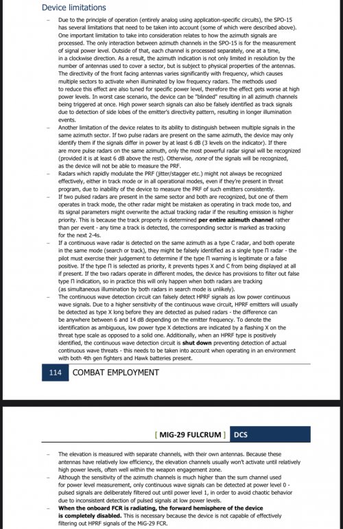
As for synchronization with radar, SPO-15 features a synchronization circuit on board 51, but it was designed for older radars such Sapfir-23. The principle of operation is the same as in older SPO-10, the receivers are blocked in rhythm with own radar's pulses. It cannot handle CW or HPRF signals (which trigger CW circuits anyway, followed by them being disabled completely in all channels once HPRF is recognized), so if they are emitted the affected hemisphere is shut down completely. According to electrical schematics for the aircraft, the N019 produces a single signal wire, which is used to block forward hemisphere, so that SPO can be left on and at least the rear hemisphere remains usable. Radio equipment manual confirms this. Full synchronization would require additional signals, so even if Cartridge 51 was modernized it would also require additional changes to wiring and to radar itself. Additionally every single channel in forward hemisphere on both boards #54 would need to be modified, so only CW signals were blocked, which is not avoidable. Failure of this system would cause the device to be flooded by own radar, making it completely unusable with radar on.
hope that helps clarify some points.
thank you


Aeria Gloria
ACCESS: Secret
- Joined
- 8 February 2024
- Messages
- 372
- Reaction score
- 431
Interested in what people think of this and the general “radar synch” issue of SPO-15. It seems LPRF circuits were retained from MiG-23 and ones designed to handle pseudo continuous signals from MPRF/HPRF were not designed for it.
Other interesting thing, SPO-15 uses an interesting method of decreasing effect of sidelobe and weak signals, by taking overall sum of signals from all channels, inverting the signal and multiplying it by a certain factor, then applying this inverted signal to all channels to attenuate strong signals and decrease weak ones. I assume this is partly why it has such weak performance of the 50/90 virtual channel that detects emitters at 85-95 degrees, here it needs to find signal of correct ratio in both rear antenna and side 50:90 antenna. However from 85-95 degrees this is far in sidelobe of both antennas. Thus this virtual 85-95 degree channel can only be triggered at close range especially with this weak/sidelobe signal suppression technique.
Also. The rear antennas are about 3db weaker and the amplifiers amp them by 3db more then the front ones in order to have equal signal strength in all sectors! I wonder what this did for signal to noise ratio and false alarm rate
Шурави1983
ACCESS: Confidential
- Joined
- 12 May 2025
- Messages
- 59
- Reaction score
- 58
LukaszK
I really should change my personal text
- Joined
- 15 January 2018
- Messages
- 132
- Reaction score
- 180
Nice document Tasnif. Contains somehow detailed description of SPO-15.
My impression - this device, designed and introduced in mid - late70tees presents its time, Soviet (somehow behind west/ US) technological level of development.
It is rather simple device, that accounts for threats existing in time of its design. (Nike - Hawk, Hercules and similar).
Generally was capable to detect impulse , continues , and probably mixed (impulse - Doppler) type of radar.
It had in initial state of processing separate path to process continues -wave radars - those have much lower emitted power.
So it is simple, relatively lightweight device. Its main aim seems to be to warn pilot about imminent threat - like close(ing) antiaircraft missile systems, and danger of launching missile.
This device probably provides much less overall situation awareness - what kind of search radars are , what type and where.
In my opinion this is due probably somehow limited selectivity (in frequency and in space), limited sensitivity (it is said, that detection range is at least 120% of firing range of potential threat system) and probably in somehow poor presentation of "secondary threats". They are marked with green lights, and corresponding type is also depicted by separate green light - but how to sort which one corresponds to which? It even has switch - that enable/disable presenting of search radars "in complex environment".

переключатель «ОБЗОР» - отключение индикации об
обзорных РЛС при полете в сложном радиолокационном поле;
Station had two basic variants "L" (like light? for lighter aicrafts) :
Существует две модификации станции: Л006 - для
установки на тяжелых и средних самолетах и Л006Л - для установки на
легких самолетах и вертолетах.
8. Масса: Л006 - 28 кг; Л006Л - 18 кг.
There are two versions of the station: L006 - for installation on heavy and medium aircraft, and L006L - for installation on light aircraft and helicopters.
They differs generally that light version has no second directional detectors in rear - just rear left and rear right.
General processing is as follows. They have 16 input channels (in SPO-15 "full") +2 additional antennas for upper and lower hemisphere detection. Processing in each channel is done the same:

It is generally direct energy detector (no frequency conversion). Generally it is possible to separate processing to two bands - upper and lower. This conversion sequentially in block called "Diplexer" (see above fig), so only once band at time is processed. And that is all frequency selection that exists. (This can be selected when in control panel - there is switch changed to position "ABTOMAT" Auto.). Then is detector and amplifier. This is done in antenna module. Next signal is passed to central device. First there is input module - in which - the mentioned above sum signal is subtracted - this reduce sensitivity but prevents from false alarms from antenna sidelobes . Then there is wideband amplifier (WU). Here processing is somehow separated for impulse signal (upper path) and continues wave (lower path). In impulse path - there is detected signal when it is above some threshold. And this detection repeats at least 3 times in some limited time (10ms). Continues signal is processed in separate path.
At output there is indication of detecting impulse radar or continues wave radar. Also detection of "locking" (tracking)- just if illumination signal is longer than 125..250ms. So, at the output there are 3 flags: «II» "I" - like impulse, "H" "N" - like non - interrupted, and "3" "Z" - like «3» («Захват»). "Zachvat"
Also (as I understand) - signal power is estimated, just by comparing signal level with set of thresholds (in dB scale). There are two devices : separately for impulse signal , and for continues signal, 15 levels are estimated.
Next processing is done by central device. It sequentially checked each channel for presence of "I" or "N" flag. This is done with clock 12.5kHz. If there is positive flag (either "I" or "N") - it stops checking and analysis of that channel is performed. In that analysis - signal level is copied to separate register (per channel) and compare with previous value. Also signal strength of main channel (main signal) may be updated. Also - estimation of RPM is done (by separate counter that detects) time between pulses. Output is one of below:

Also impulse length is estimated in separate device.
Based on that data:

Type of radar (impulse , continues ), PRF , Impulse length, frequency channel (one of 2), type of ilumanation ("Zachvat) and "Type 10"
There is determined type of radar.
After estimating that parameters - processing continue to the next channel.
Once having radar estimated radar parameters and its type - there is selected the most dangerous signal (radar). This is also done - based on some hardwired (literally) rules. Rules can be changed, by physically soldering some parts. I think this can be done by technican/specialist - to adapt behaviour to current threats / situation
"Cassette No. 57 is a software device that sets the repetition frequency and input pulse duration limits used to identify
arbitrary radar types.
Cassette No. 58 is designed to install the program
for identifying arbitrary radar types. It consists of:
35
- "Type Program" circuit, which determines the type
of the emitting radar and generates the corresponding signal "Type 1" - "Type 6";
- "Type Scale" and "Frequency Divider" circuits, in which
each arbitrary radar type is programmed with its own
frequency divider pulse rate, which determines the speed
of the missile marker on the indicator's power scale;
- "Power Zone" circuit, in which the position of the kill zone marker on the indicator's power scale is programmed for each type.
Programs are installed in cassettes No. 57 and 58 by soldering jumpers between the contacts on the mounting board."
Please take word "program" with a grain of salt... as this rules are somehow hardwired logical circus. They can be changes. As well as assignment of "radar" to type, and some other "constants" - like "missile speed" , "range of system" etc.
Some more information about - power level (marked also as approximate range) are presented only for "the highest priority target".
Power/Range scale is displayed counterclockwise. At some point - there is marked "engagement zone" (Blinking diode on range/signal strength scale) On the other side there is "depicted" missile approaching - clockwise:
"The attack missile's movement is displayed on the scale by the movement of a marker flickering at a frequency of 8 Hz (the missile marker). The missile marker "moves" clockwise, starting at the 15th power level. The time interval after which the next marker begins to flicker is determined by the timing computer, taking into account the type of attack vehicle. The "movement" of the missile marker
begins with the illumination of the "Main Radar Position" marker. To reduce the error in determining the launch time
of the missile, the station is equipped with a correction for the start of the missile marker
movement based on a signal from the onboard thermal direction finder. If a signal from this receives a signal from the timing computer, the "Main Radar Position" marker on the indicator begins to flash at a frequency of 2 Hz.
Thus, the indicator's power scale displays the dynamics of the approach to the missile: the aircraft's position is indicated by a discretely increasing light line, and the missile's position by a flickering mark, discretely moving toward it."
(As you can read SPO-15 may receive information from thermal missile launching devices like Mak)

"
a) for all radars - green course angle markers (6) and radar types (10);
b) for the main radar:
- yellow course angle markers (7), "B-H" hemisphere (1), and
type (9) of the main radar;
- red power gradation markers (8), the boundary of the air defense system's
kill zone (gradation marker flickering at 2 Hz), and the "Capture" mode (2);
c) for a launched missile:
- "Main radar position" marker (3);
- missile marker (power gradation marker flickering at 8 Hz)."
Last edited:
LukaszK
I really should change my personal text
- Joined
- 15 January 2018
- Messages
- 132
- Reaction score
- 180
After reading document my general impression is that this system is very simple. Maybe adequate for 70tees and 80tees. But for sure very limited and not to be used later...
About advantages:
- Probably it works somehow - to warn pilot about imminent threat(s?)
- simple and lightweight (lighter than its western counterparts)
- probably sensitive enough to warn pilots about continues wave radar, and pulse Doppler- Radars - those exists in that time, including semi active missiles like Aim-7
-somehow provides information about "main" target, providing pilot some estimation about its distance engagement zone etc.
Disadvantages:
- too simple
- in each channel - all signals are put into one amplitude "bucket". If there are more than one signal - it makes no difference - this is just one amplitude over time, almost no frequency selectivity. And there is measured some pulse PRF, signal length on such combined amplitude signal. And in modern days - probably there may be plenty of signals -starting from civilian traffic control radars, trough all "own" systems, hostile, radars from other own planes etc. All in all put to this simple "two bands" channel.
This may lead to classification errors, and then determine the most danger target.
- system is designed to find most critical threat and inform pilot about that. Idea may be good: as - for case of single pilot, it limits amount of information to be understood: just one the most important thread, to cope with. But on the other hand - use of that device to enhance pilot situation awareness is limited. At least I do not understand - how pilot can recognize - which "green" light from direction corresponds to which one green from type.
- moreover - during processing steps - (for each channel - if there is a signal) there is determined its parameters (PRF, band I/II, pulse-length, and also signal strength). For main target - signal strength/radar type is further processed to asses some roughly distance to target/ launch zone. But for secondary signals - even if device has estimated signal strength/radar type information (estimated distance) is not presented to pilot anywhere on display. This is clear limitation of display unit. For example in western design this is presented in azimuth - signal strength /estimated range scale that allows to develop some understanding whats happens around like this :

(I know - this is comparison of completely two different levels system, but picture is just to present idea). In SPO-15 there is nothing like that.
And if system, has made wrong prediction about "the most dangerous system", or in reality there are more than 1 really danger system, pilot has almost no understanding about that. And he has also very limited understanding of situation around.
I think, "wrong prediction" may happens quite often: detectors in channels are very simple (primitive?) -> in each channel (almost) all signals are put into single (ok actually two) bucket -> estimated radar parameters might be wrong -> rules to determine radar type, even if maybe logical, are very simple hardwired -> selection of the most important radar is also very simple set of rules.
Fortunately - pilot can manually select radar type to be threaten as "the most important", bit this not helps in every situation.
On the other hand - in some application - this SPO station does not work alone. For example on Su-24M - it was part of BKO - airborne defense complex - controlled by digital computer. If some raw data (band I/II; signal strength, radiation type : cont, impulse; PRF impulse length) about all detected radars/channles were passed to more advanced computer - it can maybe apply more advance analysis. Apart from that - jammer stations, can , additionally process signal further. For example "Gardenia" station had possibility to work in "analysis mode" when it does not emit jamming signal - but just listen. And that might provide more information, supplement somehow deficiency of SPO-15
- limited bandwidth ~ 4 -10GHz - what may be enough in 70tees. But for sure not in 90tees and later.
Does Aim-120 radar work within this band? What about Ku radars?
Last edited:
Aeria Gloria
ACCESS: Secret
- Joined
- 8 February 2024
- Messages
- 372
- Reaction score
- 431
Yes AMRAAM does.After reading document my general impression is that this system is very simple. Maybe adequate for 70tees and 80tees. But for sure very limited and not to be used later...
About advantages:
- Probably it works somehow - to warn pilot about imminent threat(s?)
- simple and lightweight (lighter than its western counterparts)
- probably sensitive enough to warn pilots about continues wave radar, and pulse Doppler- Radars - those exists in that time, including semi active missiles like Aim-7
-somehow provides information about "main" target, providing pilot some estimation about its distance engagement zone etc.
Disadvantages:
- too simple
- in each channel - all signals are put into one amplitude "bucket". If there are more than one signal - it makes no difference - this is just one amplitude over time, almost no frequency selectivity. And there is measured some pulse PRF, signal length on such combined amplitude signal. And in modern days - probably there may be plenty of signals -starting from civilian traffic control radars, trough all "own" systems, hostile, radars from other own planes etc. All in all put to this simple "two bands" channel.
This may lead to classification errors, and then determine the most danger target.
- system is designed to find most critical threat and inform pilot about that. Idea may be good: as - for case of single pilot, it limits amount of information to be understood: just one the most important thread, to cope with. But on the other hand - use of that device to enhance pilot situation awareness is limited. At least I do not understand - how pilot can recognize - which "green" light from direction corresponds to which one green from type.
- moreover - during processing steps - (for each channel - if there is a signal) there is determined its parameters (PRF, band I/II, pulse-length, and also signal strength). For main target - signal strength/radar type is further processed to asses some roughly distance to target/ launch zone. But for secondary signals - even if device has estimated signal strength/radar type information (estimated distance) is not presented to pilot anywhere on display. This is clear limitation of display unit. For example in western design this is presented in azimuth - signal strength /estimated range scale that allows to develop some understanding whats happens around like this :
View attachment 797756
(I know - this is comparison of completely two different levels system, but picture is just to present idea). In SPO-15 there is nothing like that.
And if system, has made wrong prediction about "the most dangerous system", or in reality there are more than 1 really danger system, pilot has almost no understanding about that. And he has also very limited understanding of situation around.
I think, "wrong prediction" may happens quite often: detectors in channels are very simple (primitive?) -> in each channel (almost) all signals are put into single (ok actually two) bucket -> estimated radar parameters might be wrong -> rules to determine radar type, even if maybe logical, are very simple hardwired -> selection of the most important radar is also very simple set of rules.
Fortunately - pilot can manually select radar type to be threaten as "the most important", bit this not helps in every situation.
On the other hand - in some application - this SPO station does not work alone. For example on Su-24M - it was part of BKO - airborne defense complex - controlled by digital computer. If some raw data (band I/II; signal strength, radiation type : cont, impulse; PRF impulse length) about all detected radars/channles were passed to more advanced computer - it can maybe apply more advance analysis. Apart from that - jammer stations, can , additionally process signal further. For example "Gardenia" station had possibility to work in "analysis mode" when it does not emit jamming signal - but just listen. And that might provide more information, supplement somehow deficiency of SPO-15
- limited bandwidth ~ 4 -10GHz - what may be enough in 70tees. But for sure not in 90tees and later.
Does Aim-120 radar work within this band? What about Ku radars?
I don’t think gardenia would help much, the gardenia only has a front and back antenna
It is a defensive system, and a good pilot should treat is “optional” and not a requirement for the mission. It is a luxury.
Attachments
Шурави1983
ACCESS: Confidential
- Joined
- 12 May 2025
- Messages
- 59
- Reaction score
- 58
1. The interface is stone-age-punk, while the processing tech is developed enough for cold war. Measurement is done for power, period and PRI, and possible attempt of splitting signals from mixed.After reading document my general impression is that this system is very simple. Maybe adequate for 70tees and 80tees. But for sure very limited and not to be used later...
About advantages:
- Probably it works somehow - to warn pilot about imminent threat(s?)
- simple and lightweight (lighter than its western counterparts)
- probably sensitive enough to warn pilots about continues wave radar, and pulse Doppler- Radars - those exists in that time, including semi active missiles like Aim-7
-somehow provides information about "main" target, providing pilot some estimation about its distance engagement zone etc.
Disadvantages:
- too simple
- in each channel - all signals are put into one amplitude "bucket". If there are more than one signal - it makes no difference - this is just one amplitude over time, almost no frequency selectivity. And there is measured some pulse PRF, signal length on such combined amplitude signal. And in modern days - probably there may be plenty of signals -starting from civilian traffic control radars, trough all "own" systems, hostile, radars from other own planes etc. All in all put to this simple "two bands" channel.
This may lead to classification errors, and then determine the most danger target.
- system is designed to find most critical threat and inform pilot about that. Idea may be good: as - for case of single pilot, it limits amount of information to be understood: just one the most important thread, to cope with. But on the other hand - use of that device to enhance pilot situation awareness is limited. At least I do not understand - how pilot can recognize - which "green" light from direction corresponds to which one green from type.
- moreover - during processing steps - (for each channel - if there is a signal) there is determined its parameters (PRF, band I/II, pulse-length, and also signal strength). For main target - signal strength/radar type is further processed to asses some roughly distance to target/ launch zone. But for secondary signals - even if device has estimated signal strength/radar type information (estimated distance) is not presented to pilot anywhere on display. This is clear limitation of display unit. For example in western design this is presented in azimuth - signal strength /estimated range scale that allows to develop some understanding whats happens around like this :
View attachment 797756
(I know - this is comparison of completely two different levels system, but picture is just to present idea). In SPO-15 there is nothing like that.
And if system, has made wrong prediction about "the most dangerous system", or in reality there are more than 1 really danger system, pilot has almost no understanding about that. And he has also very limited understanding of situation around.
I think, "wrong prediction" may happens quite often: detectors in channels are very simple (primitive?) -> in each channel (almost) all signals are put into single (ok actually two) bucket -> estimated radar parameters might be wrong -> rules to determine radar type, even if maybe logical, are very simple hardwired -> selection of the most important radar is also very simple set of rules.
Fortunately - pilot can manually select radar type to be threaten as "the most important", bit this not helps in every situation.
On the other hand - in some application - this SPO station does not work alone. For example on Su-24M - it was part of BKO - airborne defense complex - controlled by digital computer. If some raw data (band I/II; signal strength, radiation type : cont, impulse; PRF impulse length) about all detected radars/channles were passed to more advanced computer - it can maybe apply more advance analysis. Apart from that - jammer stations, can , additionally process signal further. For example "Gardenia" station had possibility to work in "analysis mode" when it does not emit jamming signal - but just listen. And that might provide more information, supplement somehow deficiency of SPO-15
- limited bandwidth ~ 4 -10GHz - what may be enough in 70tees. But for sure not in 90tees and later.
Does Aim-120 radar work within this band? What about Ku radars?
2. Soviet SPO, Radar and EW systems would have problems on cooperating. For individual jets, the RWR must avoid receiving when the carrier's own radar is transmitting; there are also problem of cooperating between carriers. However some simple cooperations could be done, like auto directing anti-radiation missiles, etc.
> "Применение информационных помех против БРЛС атакующего самолета и головки самонаведения атакующей ракеты часто имеет ограничения. При работе информационных средств самолетов-противников и ГСН их ракет в одном частотном диапазоне одновременное наведение своей ракеты и применение помех не допускаются. Другое ограничение на применение помех возникает, когда вблизи очага боя находятся самолеты своей группы." (The use of jamming against an attacking aircraft's radar and an attacking missile's seeker often has limitations. When the enemy aircraft's information systems and their missile's seeker are operating in the same frequency range, simultaneously guiding one's own missile and jamming it is ineffective. Another limitation on jamming arises when there is a risk of detection near the target's target.)(https://web.archive.org/web/20130712030758/http://www.permag.perm.ru/real_bvr.htm )
3. SPO-15 could only determine planar direction within a limited elevation range(which is inherited by later SPO-32), because it use 2 antennas to do monopulse measurement(more advanced? - interferometer) of planar direction, rely on the ratio between gains, on demanded planar direction, of the antenna with a limited error. The ratio indeed change when elevation angle change.
From what I read, the western method alse use 2 antennas to do similar thing, thus, error exists. The soviets way only give the proximity result, that't the difference.
- limited bandwidth ~ 4 -10GHz - what may be enough in 70tees. But for sure not in 90tees and later.
Only AIM-120C7 and C8/D have Ku-band ( 12-18GHz) radar seekers ( don't have data for the C5/C6).Meteor also has Ku-band seeker like Russian R-37M and R-77-1 ( used for the ARH mode).
During 1990's ,e.g. during NATO intervention in former FRY ,year 1999 , SPO-15LM in the YuAF MiG-29B's were very useful ,of course in the cases where they were fully operational and w/o malfunctions. NATO fighters F-15C and F-16CJ/AM used AIM-120B and C4 ( maybe even C5).
Aeria Gloria
ACCESS: Secret
- Joined
- 8 February 2024
- Messages
- 372
- Reaction score
- 431
I wonder how common it is to see a HPRF/MPRF signal as a CW signal at medium to long range. It can’t be the only RWR that sees such high PRF radars as CW is significant ranges.
Aeria Gloria
ACCESS: Secret
- Joined
- 8 February 2024
- Messages
- 372
- Reaction score
- 431
So, it mistakes a HPRF/MPRF signal as a CW signal for 10-16 dB before it can be identified as MPRF/HPRF, and then the emitter begins over in F category at 2 dB over threshold.
I wonder what it is exactly that requires 10-16 dB to process a signal mistaken as CW into properly identifying it as MPRF/HPRF. The signal strength meter is supposed to be effective radiated power ERP over threshold in 2 dB increments.
I wonder what it is exactly that requires 10-16 dB to process a signal mistaken as CW into properly identifying it as MPRF/HPRF. The signal strength meter is supposed to be effective radiated power ERP over threshold in 2 dB increments.
Шурави1983
ACCESS: Confidential
- Joined
- 12 May 2025
- Messages
- 59
- Reaction score
- 58
Interesting point! As I reading the file (with auto translation), the signal processing is with different ways/parts, in fact 'parallel'. So it decides whether it's a LPRF pulse, a CW, or different kind of MPRF/HPRF signals... then 'combine' the results with logic. In other words, for a HPRF signal, the RWR first decide 'it's a CW signal' by average power, then decide 'it's a HRPF signal' by pulse width and counting the number of pulses. Then the second decision overrides the first one.So, it mistakes a HPRF/MPRF signal as a CW signal for 10-16 dB before it can be identified as MPRF/HPRF, and then the emitter begins over in F category at 2 dB over threshold.
I wonder what it is exactly that requires 10-16 dB to process a signal mistaken as CW into properly identifying it as MPRF/HPRF. The signal strength meter is supposed to be effective radiated power ERP over threshold in 2 dB increments.
So if the second decision requires more SNR, decades by distance, there will be such a 'mistaken zone'.
Aeria Gloria
ACCESS: Secret
- Joined
- 8 February 2024
- Messages
- 372
- Reaction score
- 431
Interesting stuff about signal strength
Every added signal strength bar is -20% range
3 bars is 66% range of 1 bar
4 Bars is 50% range of 1 bar (every 3 bars decreases range by 50%)
5 bars is 40% range of 1 bar
Therefore. A knowledge pilot could actually tell a lot about closure from it.
Su-22 manual gives 15-20 km range for F category 1 bar for a 4th gen radar, this allows us to extrapolate the position of all other signal strength bars.
I assume this is a very conservative estimate, and likely for search mode. In lock mode you would often be closer to center of radar beam and have better dwell time to give higher signal strength.
Attachments
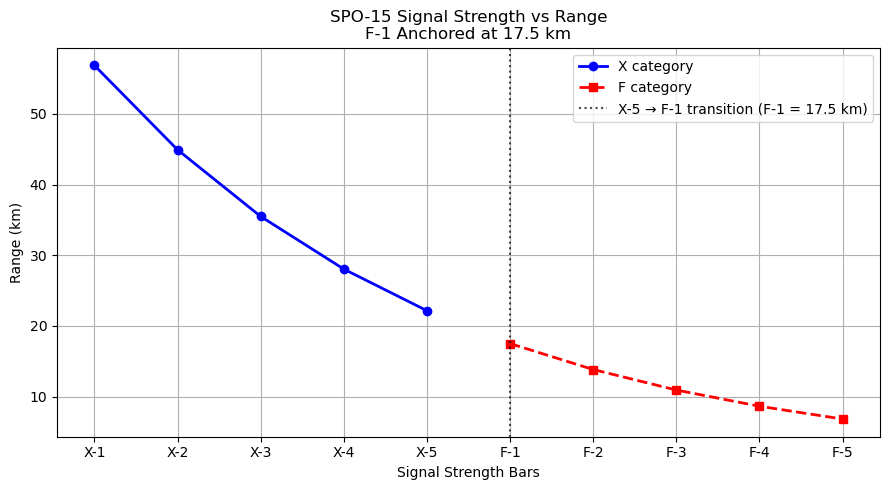
Last edited:
Aeria Gloria
ACCESS: Secret
- Joined
- 8 February 2024
- Messages
- 372
- Reaction score
- 431
Sorry this late, but this is only true for a minority of Western RWR. Usually the system takes signal strength into account and places the target on a middle or outer band depending on perceived threat level. Thus a western pilot will often have to “trust” what is on middle/inner band. Since most planes with it can only attack one plane at a time, I believe one target displayed with full information at a time was fine. Of course, it was not meant for MiG-29/Su-27 and they were considered to be retrofit with SPO-32 ASAP, its development just went too long and Soviet Union fall means a short term stop gap was no a long term band aid. Especially since these RWRs did not work with the radars either showing junk from own radar which would almost always be priority target from its strength and category and illumination time, or the front hemisphere of the SPO-15 would be turned off so the pilot can still use the Rear hemisphere. This is probably its largest weakness.For example in western design this is presented in azimuth - signal strength /estimated range scale that allows to develop some understanding whats happens around like this :
Su-27 had better shielding of SPO from radar, larger distances between them, and smaller side and back lobes from larger antenna. Thus it shows on own SPO as X category when it shows as F category on MiG-29. The advantage of it being X type for Su-27 with radar on is that if it received a F category threat (usually a 4th gen plane at short ranges of 15-50 km), it would then ignore all X type irradiation including its own radar illuminations (it is a weakness that to process high PRF F category it cannot process CW/X category) and likely show the F category threat as priority. Atleast, this is what documentation says should happen.
Let me attach a few other things

This shows priority vs altitude selected on the auxiliary control panel. MiG-29 does not have this panel and is hardwired to 8-16 km altitude, other smaller aircraft with SPO-15 are likely the same . Remember that this is only one part of the 6 part priority target selection process. Remember also that the 2 frequency bins you read about? Most documentation is about SPO-15 with auxiliary control panel. MiG-29 and other smaller fighters do not have this and are permanently wired to turn this feature off for good reason.
The frequency binning caused gaps in reception as it switched frequencies and thus would not detect search radars or other LPRF radars very well. It was not recommended to use the frequency feature except for the identification of specific radars.
So even with this panel, almost all the time, SPO-15 was in mode of not discerning frequency at all, only PRF, pulse train, pulse width, and amplitude, as long as frequency is within the allowed range that’s all that frequency would matter for in these vast majority of cases.


Here is a graphic I made using the documentation available and overlaid with graphic of antenna reception zones, the 50 zone being two antennas in parallel.

I would say other strengths include the signal strength being exactly a 20% decrease in range for every bar, 3 bars is 50% decrease in range.
In addition, 4th gen fighters are split into X at medium to long range and F at short range. While this is only because of the difficulty of processing high PRF, it gives the advantage of knowing approximate range without even seeing signal strength. Since signal strength starts over at F category, you would be able to know then that 4 bars F category is exactly 50% the range at which is switched from X type to F type, and this switch happening at approximately 33% the range of X type and 1 bar. You can see this relationship in the picture attached in my previous post. And of course showing elevation is a very unique feature.In Mi-24 the elevation antennas are omitted.
While it is “simple,” it is not the most intuitive and may take longer to “read” then the CRT of western amplitude comparison RWR and SPO-32
Here are more specs and 2 manuals. One was attached above but now this is pdf format.
Interestingly, Mikoyan was able to sync SPO-15 with Gardenia for MiG-29 9.13, at a cost of 80% sensitivity for CW and 25% for pulsed signals.
Sukhoi was not able to achieve this with Gardenia, and this Su-27SK SPO-15 also shows junk with jammer on. Who knows about Sorbitsiya.
Neither company were able to make the jammer work with the radar, turning it on forcing the jammer into rear aspect only mode same as MiG-29 does to SPO-15.
Attachments
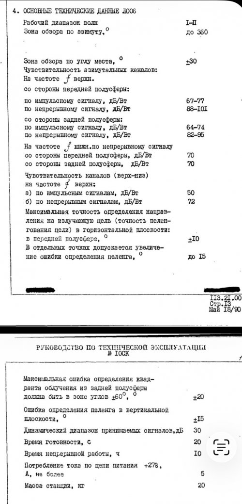
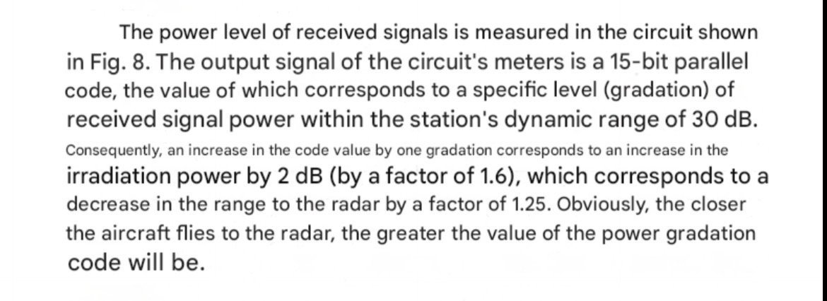
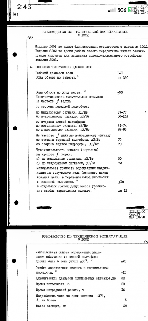
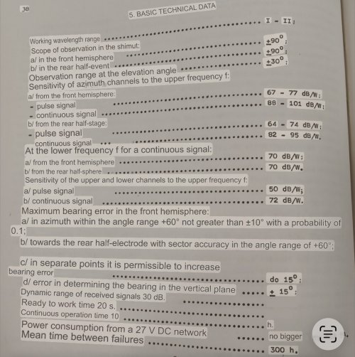
Last edited:
Aeria Gloria
ACCESS: Secret
- Joined
- 8 February 2024
- Messages
- 372
- Reaction score
- 431
I apologize if this isn’t entirely welcome.
The simulator game DCS has made a highly realistic SPO-15 simulation using physical based emulation of the radar waves in the sim and how the SPO-15 antennas receive and process the signals.
It is a mystery and very difficult to use for most people due to its complexity, lack of good documentation on its use, not being able to use the front hemisphere with radar or see launches, etc
I just released my own 25 min video on how to use it in the simulator, especially against fighters.
Even if you don’t play DCS, it may be of some academic interest as I show how to use a highly accurate model of the SPO-15 made with all the properties of its antennas and radio waves and processing.
The exact signal strength of each radar may not be exact becuase that info does not exist. But everything else seems to be thoroughly accurate.
View: https://youtu.be/ABSLoghQ5lM
The simulator game DCS has made a highly realistic SPO-15 simulation using physical based emulation of the radar waves in the sim and how the SPO-15 antennas receive and process the signals.
It is a mystery and very difficult to use for most people due to its complexity, lack of good documentation on its use, not being able to use the front hemisphere with radar or see launches, etc
I just released my own 25 min video on how to use it in the simulator, especially against fighters.
Even if you don’t play DCS, it may be of some academic interest as I show how to use a highly accurate model of the SPO-15 made with all the properties of its antennas and radio waves and processing.
The exact signal strength of each radar may not be exact becuase that info does not exist. But everything else seems to be thoroughly accurate.
Шурави1983
ACCESS: Confidential
- Joined
- 12 May 2025
- Messages
- 59
- Reaction score
- 58

Another piece on SPO-15
It was used on MIg-29 airborn computer.)))I would translate this as: Problem -Oriented with variable system of commands. In other words this v relates to system of computer instructions, in computers like C-100.
But what is relation to the previous posts?
Aeria Gloria
ACCESS: Secret
- Joined
- 8 February 2024
- Messages
- 372
- Reaction score
- 431
I have yet to see anything confirming existence of SPO-15S. I was surprised to see it here.
- Joined
- 27 December 2005
- Messages
- 18,730
- Reaction score
- 33,181
Offline sites with Pastel info, via Wayback Machine:
 web.archive.org
АО «Корпорация Тактическое Ракетное Вооружение»
- Joined
- 27 December 2005
- Messages
- 18,730
- Reaction score
- 33,181
Moved to Soviet/Russian RWR discussion.I have yet to see anything confirming existence of SPO-15S. I was surprised to see it here.
SPO-15S used on Su-24M and Tu-22M had high accuracy antennas at rear and lights all round the display, not just the front half.
Last edited:
- Joined
- 27 December 2005
- Messages
- 18,730
- Reaction score
- 33,181
Here's the SPO-15S display in an Su-24M Cockpit.


- Joined
- 27 December 2005
- Messages
- 18,730
- Reaction score
- 33,181
Oddly, the Tu-22M has a different display, with the MiG-21 silhouette, though it has 360 degree lights, as the second pic makes clearer.


Tu-22M-3 cockpit shots show this location has a blanking plate instead of an SPO-15 display, so presumably they have been refitted with Pastel RWR displaying on an CRT display.


Tu-22M-3 cockpit shots show this location has a blanking plate instead of an SPO-15 display, so presumably they have been refitted with Pastel RWR displaying on an CRT display.
Last edited:
- Joined
- 27 December 2005
- Messages
- 18,730
- Reaction score
- 33,181
It seems the SPO-15S was fitted to Su-24 as well, at least for part of the production run.The SPO-15S "Bereza-S" radar warning system had already been implemented on the previous Su-24 modification during serial production.
Aeria Gloria
ACCESS: Secret
- Joined
- 8 February 2024
- Messages
- 372
- Reaction score
- 431
Oh I see, I didn’t realize it had its own designation.Moved to Soviet/Russian RWR discussion.
SPO-15S used on Su-24M and Tu-22M had high accuracy antennas at rear and lights all round the display, not just the front half.
- Joined
- 27 December 2005
- Messages
- 18,730
- Reaction score
- 33,181
SPO-15 (MiG-25) is the original model I assume.
SPO-15L (Su-24) L Probably L stands for "Lyogkiy" (Лёгкий)
SPO-15S (Su-24M, Tu-22M)
SPO-15LM (MiG-29 / Su-27)
Other avionics items have S and M suffixes for Sukhoi and Mikoyan versions of the same item (Klyon-PM on MiG-27, Klyon-PS on Su-17) so its tempting to apply this here. The Su-27 using SPO-15LM doesn't contradict this as it adopted many of the MiG-29 avionics solutions 'off the shelf'.
Last edited:
Aeria Gloria
ACCESS: Secret
- Joined
- 8 February 2024
- Messages
- 372
- Reaction score
- 431
Yes L should be lightweight, there also lightweight and heavy versions of SPO-10, 32, I’m sure even back to SPO-2.
There is also SPO-15T digital version for Mfd Use which has 2 extra front azimuth zones as if they stopped running the 50 and 70 degree antennas in parallel and processed them separately now
There is also SPO-15T digital version for Mfd Use which has 2 extra front azimuth zones as if they stopped running the 50 and 70 degree antennas in parallel and processed them separately now
Similar threads
-
-
 Soviet GCI Command & Datalinks
- Started by overscan (PaulMM)
- Replies: 6
-

-
Ekco Red Steer radar
- Started by overscan (PaulMM)
- Replies: 0
-
Phazotron AESA radar
- Started by overscan (PaulMM)
- Replies: 9