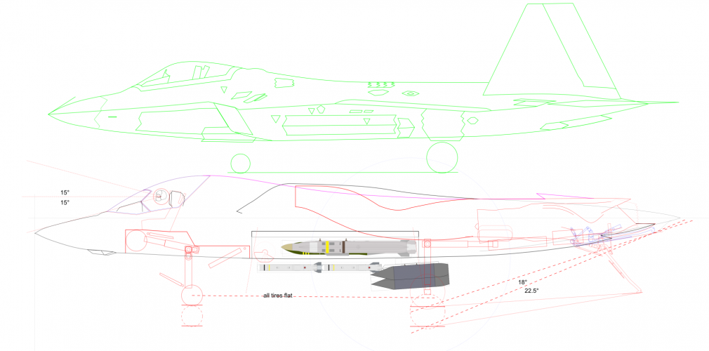
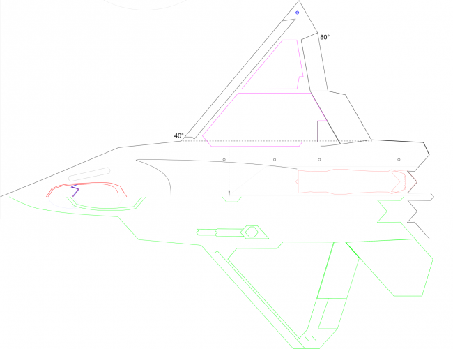
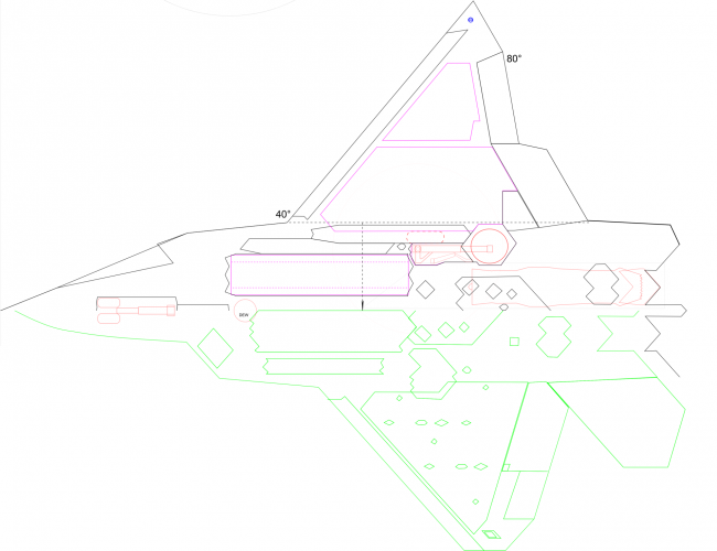
Artwork: possible configuration of the Northrop Grumman F/A-XX

It really depends on setup and planform.
As far as I'm concerned carnards and levcon are useful but with air flow control (AFC) in place not really.
I've long determined I needed two vortex streams one each over wing and body. So a split levcon is the more useful one. But with the necessary forebody angles and their play together with nose, wing, and or with fore wing... and especially in light of the wing bay setup (which comes with it's own vortex generator) I could merge and forgo of it.
And yes, small inlet below to support dorsal intake as I've been planning since the very beginning of all thse 6th gens. The function now includes AFC.

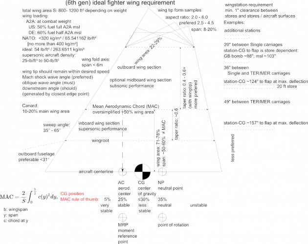
But I'm all ears for anything. Here's my general design sheet for wing planform requirement:
If there's something that needs added feel free to shoot.
 

Attachments

  • wing_6th_gen_requirement_planform.png
    wing_6th_gen_requirement_planform.png
    275.5 KB · Views: 192
It really depends on setup and planform.
As far as I'm concerned carnards and levcon are useful but with air flow control (AFC) in place not really.
I've long determined I needed two vortex streams one each over wing and body. So a split levcon is the more useful one. But with the necessary forebody angles and their play together with nose, wing, and or with fore wing... and especially in light of the wing bay setup (which comes with it's own vortex generator) I could merge and forgo of it.
And yes, small inlet below to support dorsal intake as I've been planning since the very beginning of all thse 6th gens. The function now includes AFC.

But I'm all ears for anything. Here's my general design sheet for wing planform requirement:
If there's something that needs added feel free to shoot.
Do you think the AFC approach will definitely be powerful enough to handle a 50-odd thousand pound landing aircraft in a mid Pacific storm? If this was USAF requirements I might not be concerned but carrier landing handling requirements are very demanding. Not throwing stones. Is there a good resource on AFC that gave you some confidence in this respect?
 
I agree with having Levcons in place of Canards would probably be fine a less aero and mission intrusive. Levcons or canards would more than likely be used in the following flight modes and conditions:

1. Carrier launch, approach and landing. Need very good control authority and high drag, high power setting condition.
2. Close-in dog fighting, again control authority for low-speed maneuverability.
3. In-flight refueling.

Levcons would seem to have the advantage of being locked-out for LO cruise penetrations since they can fair-up to the rest of the OML. Canards can have a disadvantage here and by nature, could degrade LO for head-on and front quadrants.

Just my opinion for a good "tailless" NG F/A-XX flight controls configuration:

1. Levcons.
2. At least 3 elevons per wing trailing edge.
3. 1 to 2 upper inlaid surfaces per wing upper surface.
4. 2-D Thrust vectoring, this can go either way. USN wants better low speed dog fighting, 2-D thrust vectoring. A fleet air defense, BVR fighter, no thrust vectoring exploit better LO.
5. May or may not need wing leading edge flaps.

The above are just my opinions based upon my years at N/NG and working various programs including YF-23 and working flight control actuation systems. Also, the joys of FWB control and stability including what well developed flight controls software can offer.
In the design I threw together and put in the Boeing thread (although I could have equally put it here, but for preferences around top surface intakes, and NATF-23 was a big inspiration, I do hope NG win.) I have NATF style canards with variable dihedral. The canards are mainly deployed for landing and manouver, but I would advocate using levcons alongside the canards especially given they look reasonably straightforward to implement and would boost manouver in the delta mode.

It was only very recently, 40 years after my first books on combat aircraft that I realised the F-15 doesn't have leading edge flaps!
 
Do you think the AFC approach will definitely be powerful enough to handle a 50-odd thousand pound landing aircraft in a mid Pacific storm? If this was USAF requirements I might not be concerned but carrier landing handling requirements are very demanding. Not throwing stones. Is there a good resource on AFC that gave you some confidence in this respect?
Note, the current AFC used is different from the past where the bypass air is blown in a more or less constant manner over the surface.

A Stake in the Ground: How Boundary Layer Control Was Implemented on a Production Tactical Aircraft
Robert M. Dowgwillo
Boeing Research & Technology 2019
on F-4 & Buccaneer
https://doi.org/10.2514/6.2018-0561

NATO :
AVT-239 (2014)
https://doi.org/10.1186/s42774-025-00225-4
used with ICE, AVT-324, SVATD among others.
https://doi.org/10.2514/6.2019-0279
As you can see for subsonic range up to 4.5lb/s or ~3% is needed. I'm estimating up to 5-7% or so for supersonic.

Today, we got electric plasma induced mini explosion and pressurized mini air "blast". Both technique induce vortices to energy the airflow etc. I don't agree on plasma as that is like a RF source that can be detected. Using small amount for an air blast requires little air and require only a few "holes" downstream over the surface.

Fluidic-Oscillator-Based Pulsed Jet Actuators for Flow Separation Control
Stephan Löffler, Germany
https://doi.org/10.3390/fluids6040166
 
Note, the current AFC used is different from the past where the bypass air is blown in a more or less constant manner over the surface.

A Stake in the Ground: How Boundary Layer Control Was Implemented on a Production Tactical Aircraft
Robert M. Dowgwillo
Boeing Research & Technology 2019
on F-4 & Buccaneer
https://doi.org/10.2514/6.2018-0561

NATO :
AVT-239 (2014)
https://doi.org/10.1186/s42774-025-00225-4
used with ICE, AVT-324, SVATD among others.
https://doi.org/10.2514/6.2019-0279
As you can see for subsonic range up to 4.5lb/s or ~3% is needed. I'm estimating up to 5-7% or so for supersonic.

Today, we got electric plasma induced mini explosion and pressurized mini air "blast". Both technique induce vortices to energy the airflow etc. I don't agree on plasma as that is like a RF source that can be detected. Using small amount for an air blast requires little air and require only a few "holes" downstream over the surface.

Fluidic-Oscillator-Based Pulsed Jet Actuators for Flow Separation Control
Stephan Löffler, Germany
https://doi.org/10.3390/fluids6040166
Thanks, great to have references to fill out my Sunday morning breakfast!
 
Note, the current AFC used is different from the past where the bypass air is blown in a more or less constant manner over the surface.

A Stake in the Ground: How Boundary Layer Control Was Implemented on a Production Tactical Aircraft
Robert M. Dowgwillo
Boeing Research & Technology 2019
on F-4 & Buccaneer
https://doi.org/10.2514/6.2018-0561

NATO :
AVT-239 (2014)
https://doi.org/10.1186/s42774-025-00225-4
used with ICE, AVT-324, SVATD among others.
https://doi.org/10.2514/6.2019-0279
As you can see for subsonic range up to 4.5lb/s or ~3% is needed. I'm estimating up to 5-7% or so for supersonic.

Today, we got electric plasma induced mini explosion and pressurized mini air "blast". Both technique induce vortices to energy the airflow etc. I don't agree on plasma as that is like a RF source that can be detected. Using small amount for an air blast requires little air and require only a few "holes" downstream over the surface.

Fluidic-Oscillator-Based Pulsed Jet Actuators for Flow Separation Control
Stephan Löffler, Germany
https://doi.org/10.3390/fluids6040166
For F1 we developed electric compressor systems that could easily (and reliably) perform this function, look forward to reading the references. Mini plasma explosions(?) Nuts!!
 
Like this? Added height measurement

Yes, thanks. Similarly for top view, bottom view.
Side view - superimposed & separate.
This gives an excellent size idea of entire jet & the fuselage, IWB, weapons, etc.
Like we say "A pic is worth 1000 words" ;)
 
@Seragina, we're you going for variable dihedral tips and waverider concept? I noticed earlier, was this discussed in a post?
 
@Seragina, we're you going for variable dihedral tips and waverider concept? I noticed earlier, was this discussed in a post?
Wave riding was always at the back of my mind that I wanted to take advantage of. The problem however, is the size and spacing needed.
The F14 and the YF23 specifically is a good example with its wide separation of the intake duct and tucked-in center fuselage.
As is the fuselage might only be able to wave ride by relying on the aft section.

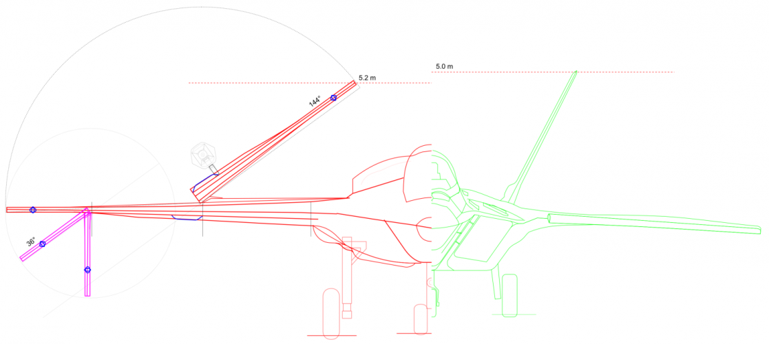
Variable dihedral tips wasn't exactly my goal. The current wing design just happens to coincide with the math. Using folding motors based on shape memory saved 80% of the conventional motor/mechanic weight. And looking by its nature I realized I could use one single motor with 180° of change to drive both wing sections by using counter rotating ends. See it can keep rotating in one direction but the rotation runs counter from each end's perspective point of view. I only need to anchor the motor onto the 2nd wing section, add some arresting mechanic to select how and which section to rotate by how much etc. It might need two drive trains, though. After seeing this I couldn't resist implementing it. With the tips down this could enable wave riding far better than ever possible with the fuselage only.
 
Yes, thanks. Similarly for top view, bottom view.
Side view - superimposed & separate.
This gives an excellent size idea of entire jet & the fuselage, IWB, weapons, etc.
Like we say "A pic is worth 1000 words" ;)
For the sides I just placed them as is but vertically separated.
 

Attachments

  • FA-XX-2025-F22-side-halves.png
    FA-XX-2025-F22-side-halves.png
    218.2 KB · Views: 121
  • FA-XX-2025-F22-top-halves.png
    FA-XX-2025-F22-top-halves.png
    150.5 KB · Views: 112
  • FA-XX-2025-F22-botton-halves.png
    FA-XX-2025-F22-botton-halves.png
    184.7 KB · Views: 108
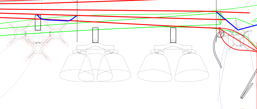
So I tried a few things for "beast mode". Although, I had seen a few images saying and showing 2 Mk84 could be mounted on a pylon rack, and the load rating supports this but it seems there aer no such rack. At least I couldn't find it. I know there had been some nice ones in the past for the F4 like the spiky supersonic TER but I doubt they are to today's standard.
I also tried to re-create the triple launcher that was obviously divised for the ACA/Eurofighter desmonstrator and supposedly also for the Tornado. But it seems I can't quite fit it to the seemingly small form factor displayed.
Anyhow, this clearly shows we are lacking a few rack options today.
 

Attachments

  • FA-XX-2025-beast_mode_load-test1.png
    FA-XX-2025-beast_mode_load-test1.png
    61.9 KB · Views: 113
Variable dihedral tips wasn't exactly my goal. The current wing design just happens to coincide with the math. Using folding motors based on shape memory saved 80% of the conventional motor/mechanic weight. And looking by its nature I realized I could use one single motor with 180° of change to drive both wing sections by using counter rotating ends. See it can keep rotating in one direction but the rotation runs counter from each end's perspective point of view. I only need to anchor the motor onto the 2nd wing section, add some arresting mechanic to select how and which section to rotate by how much etc. It might need two drive trains, though. After seeing this I couldn't resist implementing it. With the tips down this could enable wave riding far better than ever possible with the fuselage only.
Definitely needs two drive trains.
 
Back
Top Bottom