- Joined
- 3 June 2011
- Messages
- 20,896
- Reaction score
- 19,084
Any TVC? Fluidic TVC?Model 432 internal layout, length 19.5 m, wingspan 14.0 m, volume 77 m³...
Last edited by a moderator:

Any TVC? Fluidic TVC?Model 432 internal layout, length 19.5 m, wingspan 14.0 m, volume 77 m³


Beautiful model but still does not match with the official rendering, not same Nose shape , too much triangular shape fuselage, with the little picture we have Reddington777 seem to be near of the F-47 official rendering. But you can be right if the official picture is a Debunk of the real shape .... ARRRgggg it will never end before the public roll-outMost probably the best way to reduce wingspan / area without changing the overall layout too much.
I always design solid models. This way, SolidWorks can display the body volume directly.
Knowing the volume allows for an estimation of the weight. A density of around 580 kg/m³ seems appropriate to estimate the maximum takeoff weight of a modern supersonic combat jet.
More info here: https://www.secretprojects.co.uk/th...eight-multirole-fighter-lmf.38539/post-507567
112 m³ of solid body volume is truly enormous!
For comparison, my model 432 is 77 m³ "raw" (solid model, without any hollow space) and my KF-21 model, based on the KAI three-view drawing, has a volume of 51 m³. I think the F-35 has a volume of around 50–55 m³ and the F-22 around 60–65 m³.
Which brings me back to the topic of density: Ideally, we would know the exact volume of the F-22 (or a similar twin engine stealth fighter) in order to make a good estimate of its density. This would then allow us to obtain a realistic assessment of the weight of our own model.
Model 432 internal layout, length 19.5 m, wingspan 14.0 m, volume 77 m³

Yeah, I think with the given length assumption and planform shape, I dont see it going down that low. Making it shorter though might, as the rest of the dimensions scale accordingly.112 m³ of solid body volume is truly enormous!
For comparison, my model 432 is 77 m³ "raw" (solid model, without any hollow space) and my KF-21 model, based on the KAI three-view drawing, has a volume of 51 m³. I think the F-35 has a volume of around 50–55 m³ and the F-22 around 60–65 m³.
Which brings me back to the topic of density: Ideally, we would know the exact volume of the F-22 (or a similar twin engine stealth fighter) in order to make a good estimate of its density. This would then allow us to obtain a realistic assessment of the weight of our own model.
Model 432 internal layout, length 19.5 m, wingspan 14.0 m, volume 77 m³
Yeah as I was modeling it, I think a lot of the F-47 will sit between J-XDS and J-36 just because the US is building only a single air superiority fighter. There's no opportunity to have a larger and smaller air superiority fighter.My J-36 model with the troughs has a volume of 136m³, just as a upper bound value.
If that implies the wings goes up to or past the end of the plane, well I like that idea because it fits the firebird patch. The problem then is you need a high wing sweep and possibly a correspondingly high wingspan. How much wing sweep? How much wingspan? and how much of the exhausts plume do you want to cover with it?I really do love everything but I have this sneaky feeling F-47 will have very interesting main wings. I think Rodrigo’s bird like F-47 configuration comes closest for me, at least in spirit.
To crystallize the spirit of what I mean, perhaps the sweep and angle of the wings are such that it could shield the thermal signature of the exhausts 40d off of port and starboard?

Agree 100%I think a lot of the F-47 will sit between J-XDS and J-36

Yeah, I think with the given length assumption and planform shape, I dont see it going down that low. Making it shorter though might, as the rest of the dimensions scale accordingly.
Yeah as I was modeling it, I think a lot of the F-47 will sit between J-XDS and J-36 just because the US is building only a single air superiority fighter. There's no opportunity to have a larger and smaller air superiority fighter.
I think the current planform would offer a larger volume than J-XDS just because the nose seems proportionally wider. The rest of the body (assuming length is accurate) would be at least equal or possibly longer. So if the F-47 had a volume between J-XDS and J-36, I wouldnt be surprised. Given where the volume sits now, which still ends up lower than the J-36, it might still make sense - especially since J-XDS should have a larger volume than 5th gen fighters by quite a margin.
I haven't compared the fuselage thickness to the J-36 (without the dorsal intake) yet. If it ends up being thicker then Ill make it thinner. Otherwise Ill leave it as is.
Pitch (& roll) mechanical, yaw rather fluidic.Any TVC? Fluidic TVC?
If your assumed density heuristic is 580kg/m3, then that implies my model is far too big, but the central question is can you still have a MTOW of more or less 96k in a larger, and less dense planform and how much weight the added planform area translates to.With an assumed density of 580 kg/m³ and a expected MTOW of 96,000 lb (43,545 kg), this results in a volume of 75 m³. Therefore, I expect the F-47 to fall within this range. Anything significantly higher appears highly unlikely to me.
If your assumed density heuristic is 580kg/m3, then that implies my model is far too big, but the central question is can you still have a MTOW of more or less 96k in a larger, and less dense planform and how much weight the added planform area translates to.
Im not sure where the 580 number comes from (i may have found the research article on it, but that seems to be excluding cavities like intake ducts and what not), but if you assumed that measure from an F-22 or even from more conventional fighters, then it may or may not be strictly enforceable on a large lambda wing.
Taking the J36 internal volume measure of 136m3 (assuming somewhat high accuracy) and your density of 580kg/m3, and assuming the J-36 has three 40k lbf thrust engines, you get a MTOW of 174klbs and a total thrust of 120klbs, or a measly 0.69 T/WR. Thats nearly an F-35 level of T/WR and probably even less than an F-35.
There are good reasons to have a large but less dense planform. You have higher lift and larger control surfaces not to mention a flatter geometry for the same height among many others.
112m3 may well be too big, but it can also be more a function of the weight that greater surface area built with current composites adds to a given MTOW weight calculation than strictly a single measure of density.
I had literally just edited calculations based off the J36 into my comment above and found d a density of somewhere between 300 to 500 kg/m3. The 500 number came from a MTOW of 150klb and a thrust of 120klb. The more likely / average cases were between 80klb and 105klb MTOW, and combined with the 136m3 volume estimation came out to between 300 and 350 kg/m3. Applied to my 112m3 measurement, that comes out to roughly 86.5k lb MTOW, which seems in band.The 580 number comes from an earlier discussion, here: https://www.secretprojects.co.uk/th...eight-multirole-fighter-lmf.38539/post-507567
This number is not universally applicable, and the greater the deviation from the characteristics of the example aircraft, the more the result will deviate from reality. Ideally, the volume of an aircraft with comparable characteristics would be known, such as the F-22.
However, I applied that number on the F-22 (83,500 lb / 37,875 kg MTOW). The result is 65 m³ of solid body volume, which seems plausible to me. Hence, I consider it good enough for an initial assessment of my model.
That's a bigger MTOW than I've been expecting. Though I suppose 80kish mission TOW plus ~16klbs of external capacity makes sense.Size and weight of the F-47 depend significantly on its engines. It can be assumed that the XA102/103 engines deliver higher thrust than the F119, but lower than the F135 (35,000 vs. 43,000 lbf). Consequently, I expect a maximum thrust of approximately 40,000 lbf (18,144 kgf) and a maximum takeoff weight of 96,000 lb (43,545 kg). This represents a 15% increase compared to the F-22.
With an assumed density of 580 kg/m³ and a expected MTOW of 96,000 lb (43,545 kg), this results in a volume of 75 m³. Therefore, I expect the F-47 to fall within this range. Anything significantly higher appears highly unlikely to me.
My 136 cubic meters was based off an aircraft that was 21.5m long. If the J-36 was shorter like 20.5m long as has been previously speculated. This drops the volume down to 118 cubic meters.I had literally just edited calculations based off the J36 into my comment above and found d a density of somewhere between 300 to 500 kg/m3. The 500 number came from a MTOW of 150klb and a thrust of 120klb. The more likely / average cases were between 80klb and 105klb MTOW, and combined with the 136m3 volume estimation came out to between 300 and 350 kg/m3. Applied to my 112m3 measurement, that comes out to roughly 86.5k lb MTOW, which seems in band.
I did however consider how I could change the planform using the numbers you calculated. In tandem with what @Training_Dummy was saying, it could very well be that the plane has a shorter aft fuselage section (or just in general a shorter plane by scaling down all dinensions) while having even more high sweep wings. I think my intakes could probably be smaller and shorter too, which could certainly conclude in a much denser and smaller volume airframe.
Im going to complete this larger model and send it off first, then work on a smaller model with a different planform for the aft fuselage.

Explain hooded foresection!My opinion is no canard and more of a hooded fore-section. There will be more than 2 areas that open for weapons.
| J-36 Assumed Volume | J-36 Density | Max F-47 derived volume for 96k MTOW |
| 101 m3 | 403.6 kg/m3 | 92.3 m3 |
| 118 m3 | 471.6 kg/m3 | 107.9 m3 |
| 135 m3 | 350.2 kg/m3 | 124.3 m3 |
| F-47 Length | F-47 Volume |
| 18.9m - F-22 length | 86 m3 |
| 19.7m - Halfway F-22 and YF-23 length | 97 m3 |
| 20.55m - YF-23 length | 110.2 m3 |
Hooded foresection sounds like a euphemism for something bad lol...Explain hooded foresection!
I think it doesn't work this way. As said before, the density number is not universally applicable. You should choose an example aircraft of similar size and characteristics, of which you know weight and volume. We know nothing about the J-36. Neither its actual weight nor its actual dimensions.So with the numbers that Nx4eu gave, I went to see if scaling down my models and applying different densities would still accommodate the same internals.
These are the calculated densities for each given volume. Then I used each density measure to derive a volume assuming that the MTOW remains 96,000 lbs.
J-36 Assumed Volume J-36 Density Max F-47 derived volume for 96k MTOW 101 m3 403.6 kg/m3 92.3 m3 118 m3 471.6 kg/m3 107.9 m3 135 m3 350.2 kg/m3 124.3 m3
I scaled the model to three different lengths and measured their corresponding volume:
F-47 Length F-47 Volume 18.9m - F-22 length 86 m3 19.7m - Halfway F-22 and YF-23 length 97 m3 20.55m - YF-23 length 110.2 m3
...Using 403.6 kg/m3 as the density and 98m3 as the volume, then our MTOW is 87,198 lb, which still puts us somewhat higher than the F-22...
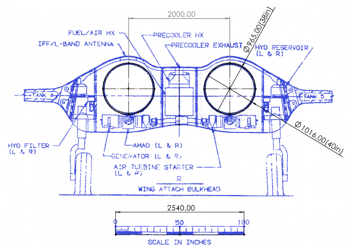
4.6 ft (55 in) is a very large diameter. The F135 has a fan diameter of 3.58 ft (41 in) and a maximum diameter of 3.8 ft (46 in). I would assume XA102/103 are in the 40,000 lbf thrust class, and therefore not larger than the F135.I made the fuselage a bit flatter and altered the contours to be a little more steep to accommodate the 4.6 ft diameter engines.
Density should be different between different aircraft and it should fall into a range like you describe, but it's also just determined by what the MTOW and volume is, which are, in turn, determined by how much thrust is available and the TWR of a given aircraft.I think it doesn't work this way. As said before, the density number is not universally applicable. You should choose an example aircraft of similar size and characteristics, of which you know weight and volume. We know nothing about the J-36. Neither its actual weight nor its actual dimensions.
I don't agree or disagree to your numbers really. As I said - it's just a matter of what numbers you are assigning to each input. This probably doesn't need explanation, but for the J-36, if you assume max thrust is always 83% of MTOW, and we go with the 118m3 derived from the 20.5m measurement of the J-36, then you get a density of 512kg/m3. Under the same assumptions, but with a volume of 101m3, you get a density of 598kg/m3. Your range can work. It just depends on MTOW.I admit that the 580 number may not be accurate as well, but I'm confident it's not far off...
Therefore, I am quite confident that a number between 500 and 600 is realistic (to determine the maximum takeoff weight of a supersonic stealth fighter based on its volume, and/or judge if the volume is within a realistic margin in relation to the anticipated maximum takeoff weight).
I can run with 46 inches. Wikipedia states 40inches diameter for the F119. As long as an additional 6 inches to diameter is enough to accomodate the third stream then all is well.4.6 ft (55 in) is a very large diameter. The F135 has a fan diameter of 3.58 ft (41 in) and a maximum diameter of 3.8 ft (46 in). I would assume XA102/103 are in the 40,000 lbf thrust class, and therefore not larger than the F135.
Reddington summed it up. With Boeing patents the canards become unecessary. Low drag to the extreme would be the target.Explain hooded foresection!
I forgot to add - are ACE engines partitioning the same volume / diameter of an F-119 sized engine? or would it be adding volume / diameter to a central chamber that's already F-119 sized?4.6 ft (55 in) is a very large diameter. The F135 has a fan diameter of 3.58 ft (41 in) and a maximum diameter of 3.8 ft (46 in). I would assume XA102/103 are in the 40,000 lbf thrust class, and therefore not larger than the F135.
It is, but 50-52" would seem reasonable. 55" is the diameter of the F101. ~48" is the max diameter of F100, 110, F119, and even F135.4.6 ft (55 in) is a very large diameter. The F135 has a fan diameter of 3.58 ft (41 in) and a maximum diameter of 3.8 ft (46 in). I would assume XA102/103 are in the 40,000 lbf thrust class, and therefore not larger than the F135.
I have been assuming that they're a little bigger. ~2" ish.I forgot to add - are ACE engines partitioning the same volume / diameter of an F-119 sized engine? or would it be adding volume / diameter to a central chamber that's already F-119 sized?


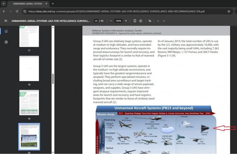
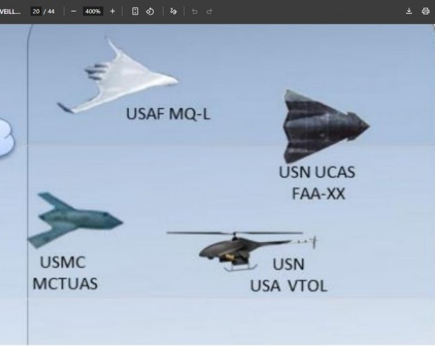
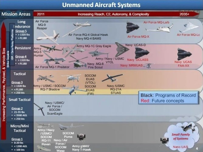
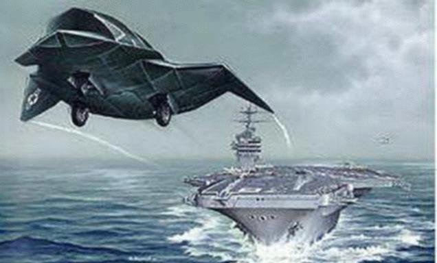
Woah. Im more interested in the MCTUAS. Looks like the bird of prey. Also pretty interesting they listed the F/A-XX as unmanned.Came across this today, in a pdf from 2018.
Text says "USN - UCAS - FAA-XX" but the shape makes me think about the nice assumptions, calculations & creations in this (USAF F-47) thread.
Most probably the image has already been shared somewhere on the forum before (?) but I can´t remember and there are way too many posts about PCA, NGAD, F-47, F/A-XX, etc. for me to go through to check..
Also pretty interesting they listed the F/A-XX as unmanned.
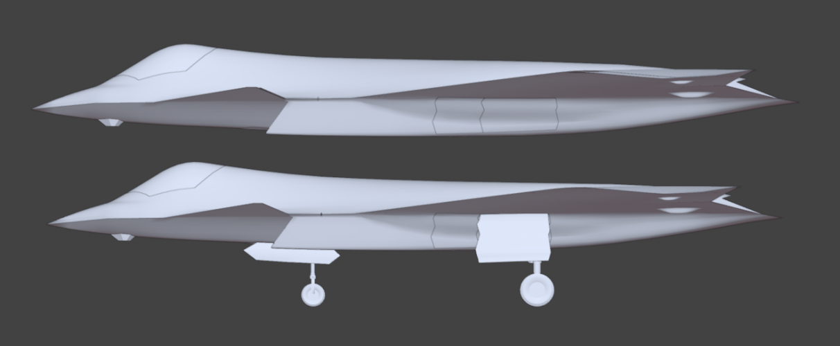
I've reached a volume of 80 m2 at 62.2 ft and a density of 544.31 kg/m3. It's taken on a very F-22 looking side profile:Therefore, I am quite confident that a number between 500 and 600 is realistic (to determine the maximum takeoff weight of a supersonic stealth fighter based on its volume, and/or judge if the volume is within a realistic margin in relation to the anticipated maximum takeoff weight).
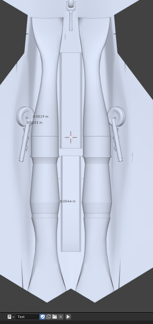
1-2" wheel well clearance is tight but doable. You'd need to carefully plan where any reinforcing rings are around the inlets, and where any ribs are around the inside of the bays.I've reached a volume of 80 m2 at 62.2 ft and a density of 544.31 kg/m3. It's taken on a very F-22 looking side profile:
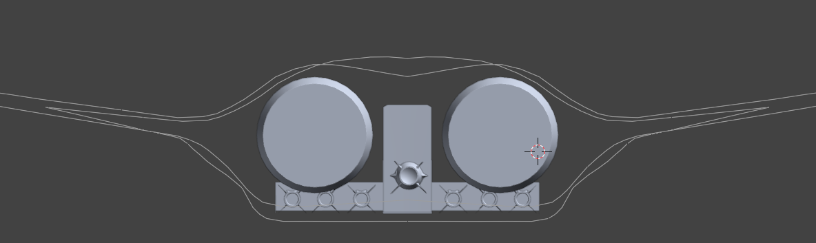
I want to confirm some internals with people:
The wheel clearance and weapon bay clearance seems really really small.
0.0251m (0.988 inches) is the smallest clearance the wheel has to the outer bay doors.
0.0519 m (2.04 inches) is the shortest distance from the wheel to the intake walls.
0.0544 m (2.14 inches) is the shortest distance from the engine casing to the weapon bay wall.
Are these clearances at all plausible? What clearances should I be observing here?
This is after I had to reduce the rear weapon bay width. It carries a tightly packed 3 - 4 AAMs but can't fit two SiAW anymore. Only the front bay can fit that.
View attachment 795323
F135-PW-100 (43,000 lbf):It is, but 50-52" would seem reasonable. 55" is the diameter of the F101. ~48" is the max diameter of F100, 110, F119, and even F135.
Going off of wikipedia numbers:F135-PW-100 (43,000 lbf):
Max: 46" (1168 mm)
Inlet: 43" (1092 mm)
Fan: 41" (1041 mm)
I don't think the XA102/103 would exceed these dimensions. It could even be a few inches smaller.
That FAA-XX UCAS is pretty old. I've seen pics of it around years ago.Came across this today, in a pdf from 2018.
Text says "USN - UCAS - FAA-XX" but the shape makes me think about the nice assumptions, calculations & creations in this (USAF F-47) thread.
Most probably the image has already been shared somewhere on the forum before (?) but I can´t remember and there are way too many posts about PCA, NGAD, F-47, F/A-XX, etc. for me to go through to check...

Yeah I just haven't modeled it, but the wheels should be in a bay. All these numbers aren't even counting the distance to the separating walls, which I also have no idea how thick they may be.The powers that be will not like having the inlets visible through the landing gear doors, so there's a physically separate bay from the inlets. Yes, that adds weight, but it also adds strength.
As I drop the volume, I'm starting to think there's basically only one configuration that's viable on a sub 80m3 stealth fighter and that's the F-22 configuration where you have your weapon bays tucked under your intakes. You can do it the YF-23 way, but that means you'll have sections of airframe with some deep trenches in between those sections of your airframe.I just flat think that the distance between the engine centerlines is too close. Need to scale things up a bit.
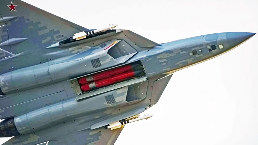
Not sure. I was using the Su-57 as reference, but not sure how much actual distance is between the bay and the engines here.What was the distances between the engines and weapons bay of the A-5 again? I'd probably use that as the minimum viable.
6.3 inches.Edit: what do those dimensions look like if you make the beast 68ft long?

1997 at latestThat FAA-XX UCAS is pretty old. I've seen pics of it around years ago.

Form factor means "fits within all the same maximums", so that's max width/height, diameter, and length.X102/3 was said to be scaled down from AETP, which was supposed to fit the F135 form factor, but who knows if that's length? width? both?
Call it 1" for each wall as a minimum, more like 2" if it's load bearing. And that leaves very little access for assembler's hands and tools.Yeah I just haven't modeled it, but the wheels should be in a bay. All these numbers aren't even counting the distance to the separating walls, which I also have no idea how thick they may be.
The mere fact that there's lots of unused space under the intakes strongly suggests that this is where at least a few bays are.As I drop the volume, I'm starting to think there's basically only one configuration that's viable on a sub 80m3 stealth fighter and that's the F-22 configuration where you have your weapon bays tucked under your intakes. You can do it the YF-23 way, but that means you'll have sections of airframe with some deep trenches in between those sections of your airframe.
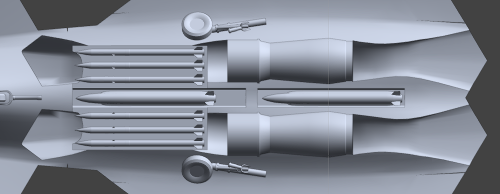
What I think could work is to have something akin to the J-36, which is two narrow, tandem middle bays for the two SiAW. Then adjacent to the narrow middle bays are two flatter, but wider bays to hold the AAMs in. This way, there's also no interference between dropping those AAMs. The planform I'm working with also happens to have a lot of unused space under the intakes. This would also allow me to center the engines a bit more to fit the aft fuselage contours and also create space for the main landing gear stowage bays.
Edit: Like this:
View attachment 795446
The intakes currently cut through the bay, but I'm going to make the bay conformal around it. The tip of the AIM-260s have 3.24 inches of clearence with the wall of the intakes, so counting the bay walls, something like 1-2 inches of clearance with the intakes. The central bays have a 3.4 inches of clearance with the widest most point of the engine. It's also got plenty of depth and headroom for whatever goes there. This also let's you decide to carry either SiAW/AARGM-ER or some future LRAAM for the center bays while guaranteeing six AAMs no matter which load out you carry. If you really wanted to go crazy with it, you could stick two more sidewinder bays on the side and switch out the center bays for AAMs as well for a total of 10 missiles.
The wheels now have much more breathing room and enough space for a wheel bay and the engines fit better with the tightest bulkhead. The best part is that all of this seems as of now comfortably packaged in 84m3 and could possibly be reduced down to 78m3, which also works with the density that @VTOLicious arrived at.
View attachment 795448
That's a picture very close to flat on, do we have the length of any of those missiles?Not sure. I was using the Su-57 as reference, but not sure how much actual distance is between the bay and the engines here.
View attachment 795440
Ah, yeah, that throws a monkey wrench into the works.6.3 inches.
But that has an 105m3 volume. My J-36 referece (assuming max thrust is 80-84% of MTOW, 3x 35,000k lbs engines, 130klb MTOW) has a density of 497.75kg/m3 for the J-36 reference. With that density, The most volume I can reason away with for 96klb MTOW is only 87m3.
Certainly possible, though there'd be a whole lot of adjustments overall.i just wonder
since Boeing merge with McDonnell-Douglas
Could F-47 based on JAST 7 concept by McD-D ?
Wikipedia is wrong - the maximum diameter of the F119 is not larger than the F135. I don’t have exact figures, but horizontal maintenance on the F119 is performed on the standard USAF 3100 work rails with a 48” spacing, and the engine fits within that spacing. The F135 can be transported on a standard 3000E trailer with 48” rail spacing, but the transportation adapter hangs over the rails. Any horizontal maintenance is done on work rails with 60” spacing to allow space for the support adapters.Going off of wikipedia numbers:
F135: Diameter: 46 in (1,170 mm) max., 43 in (1,090 mm) at the fan inlet
F119: Diameter: Approx. 40 in (100 cm) inlet, 48 in (120 cm) overall, 50 in (130 cm) maximum
The language is sorta vague but F135 seems to have a wider inlet while F119 is wider overall.
Length wise, F135 is larger.
X102/3 was said to be scaled down from AETP, which was supposed to fit the F135 form factor, but who knows if that's length? width? both?
That FAA-XX UCAS is pretty old. I've seen pics of it around years ago.