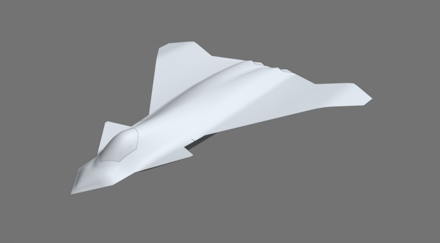
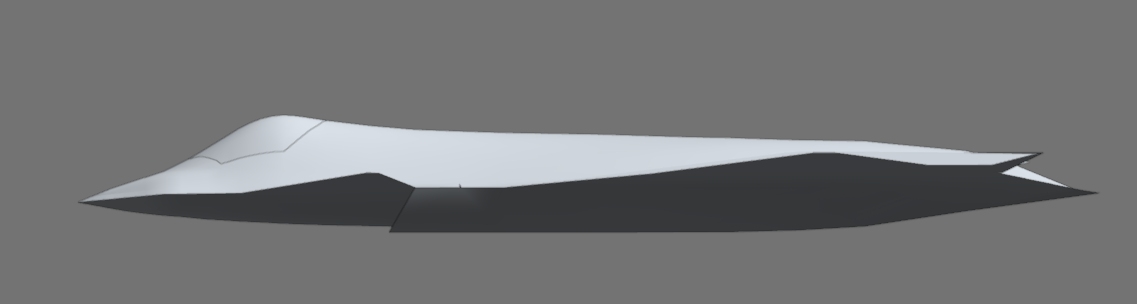
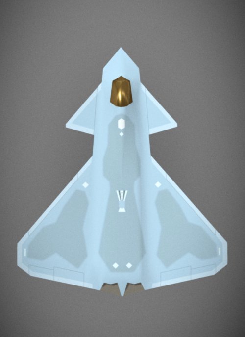
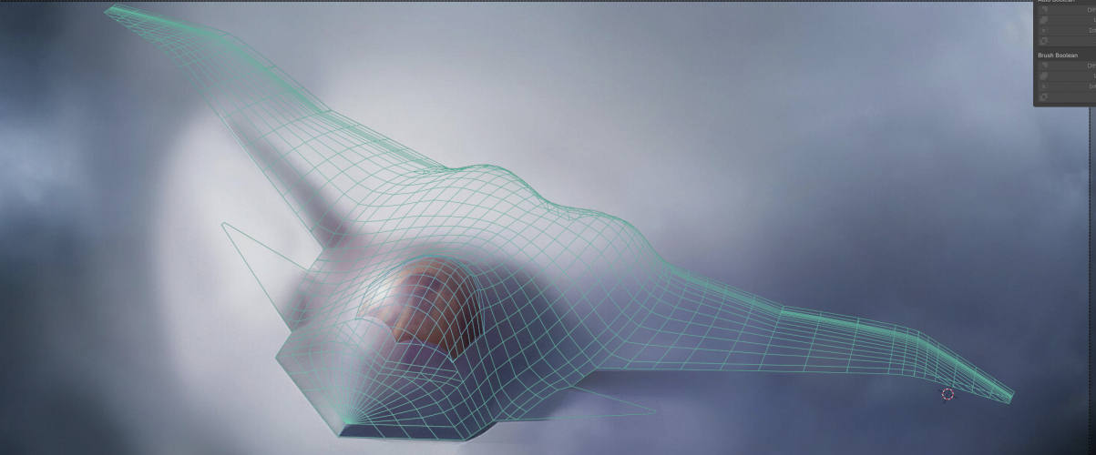
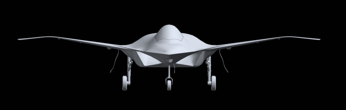
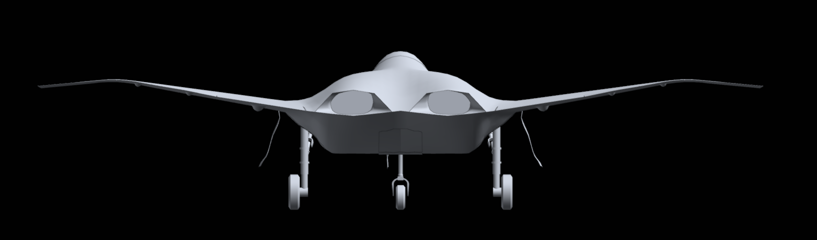
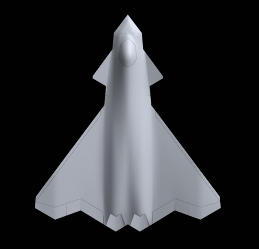
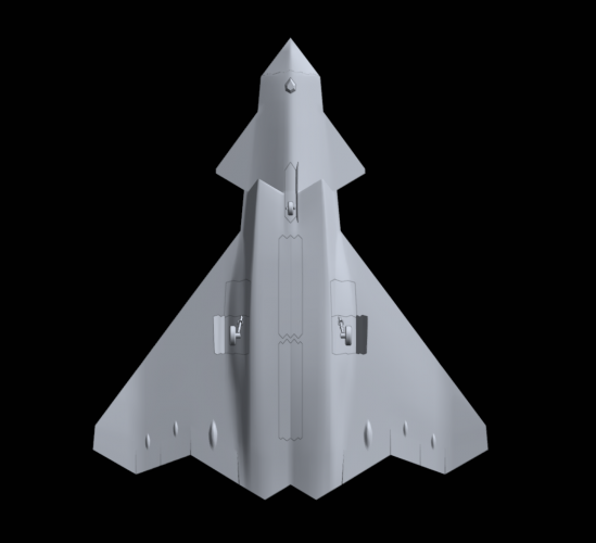
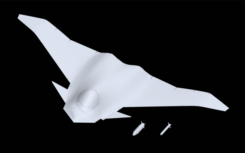
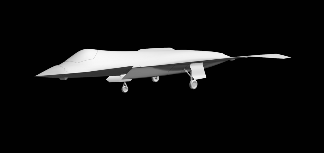
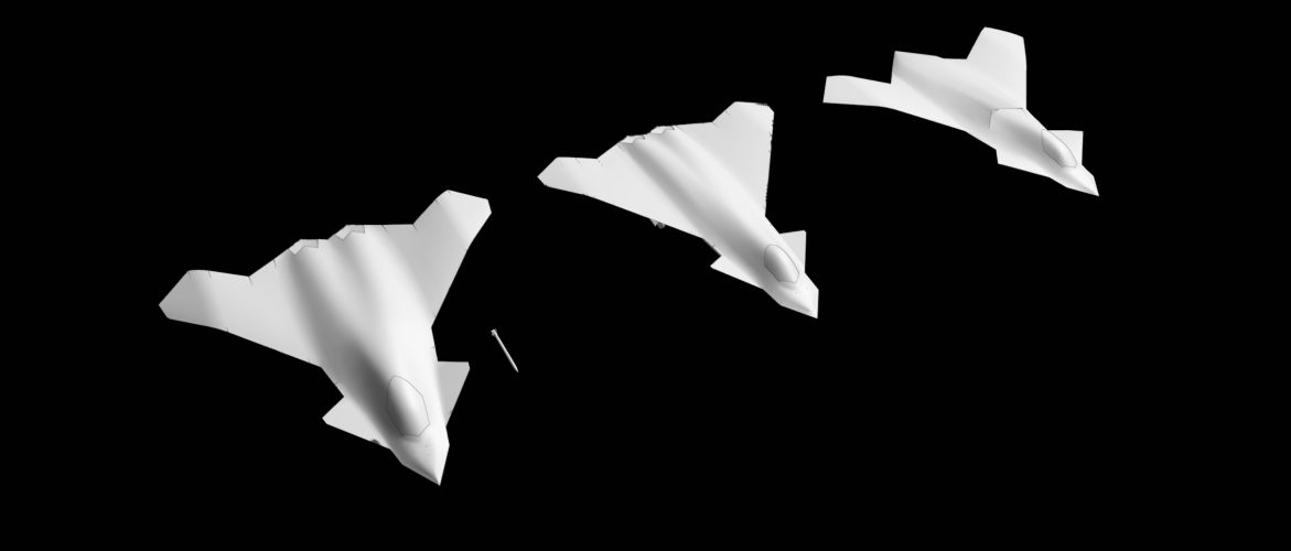
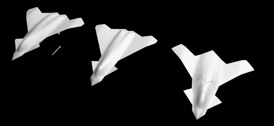
Starting to take shape here. Not horrible looking either.
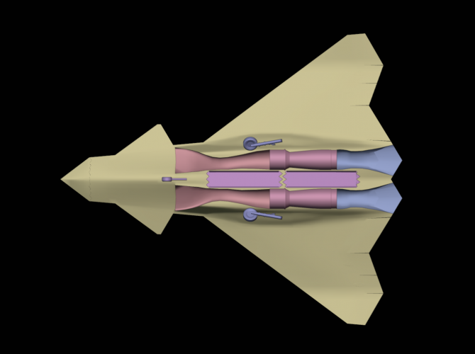
It's got less volume now than the wider model, but I could still fit two 14ft long tandem bays each with 3 - 4 AMRAAM sized missiles in a staggered formation. For reference the wider planform had enough volume to fit 14ft tandem bays each carrying 5 AMRAAM sized missiles comfortably.
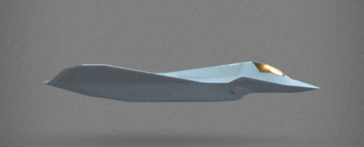
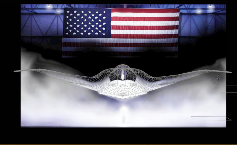
This is not my model. I found it on the web and everything is starting to take shape. It looks very similar to yours Reddington777. View attachment 794175View attachment 794176
Starting to take shape here. Not horrible looking either.
It's got less volume now than the wider model, but I could still fit two 14ft long tandem bays each with 3 - 4 AMRAAM sized missiles in a staggered formation. For reference the wider planform had enough volume to fit 14ft tandem bays each carrying 5 AMRAAM sized missiles comfortably.
Lower quality, I spent less time on it like you guys but I went with a simpler platform alignment, something like the YF-23, and the nozzles are like the Boeing ATF submission.
This is not my model. I found it on the web and everything is starting to take shape. It looks very similar to yours Reddington777. View attachment 794175View attachment 794176
Yeah This is based off the alignment that @targetpractice had so that would be why it's very similar. He was kind enough to share the .blend file with me.
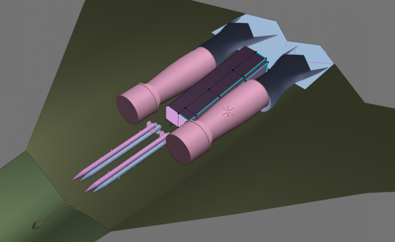
The current model does have enough space to fit 4 AMRAAMs in a single bay. The AARGM-ER/SiAW is 13.8 ft long. lengthening the bays by a few more inches shouldn't be a problem. Width wise, I think the forward weapon bay should have enough space for 2 SiAW form factor weapons side by side. I haven't modeled the SiAW yet so what you see in the screencaps are AIM-260s, but it looks wide enough.
If not though, the weapon bays can't go wider due to the engine clearence but it might be able to go deeper (taller). Then you could have 2 door mounted AMRAAMS + a single SiAW hanging on the bay ceiling per bay.
Or if we were talk an 75ft (22.4m) long planform (F-111 sized) then you'd comfortably have space to widen the forward bay. The current model remains 68 ft (20.7m).
If not though, the weapon bays can't go wider due to the engine clearence but it might be able to go deeper (taller). Then you could have 2 door mounted AMRAAMS + a single SiAW hanging on the bay ceiling per bay.
Starting to take shape here. Not horrible looking either.
It's got less volume now than the wider model, but I could still fit two 14ft long tandem bays each with 3 - 4 AMRAAM sized missiles in a staggered formation. For reference the wider planform had enough volume to fit 14ft tandem bays each carrying 5 AMRAAM sized missiles comfortably.
i don't think the airforce would allow stacked missiles like this, inside internal weapons bay that is. due to my understanding a pilot must select what weapon to use on the station and if they select the upper amraam it may jam or cause a failure, obviously i could be wrong especially with a easy fix of just programming it to launch based on weapon type instead of individuals. another reason i don't think this would fly would be if the first missile fails to eject you'd now be down two missiles instead of one
i don't think the airforce would allow stacked missiles like this, inside internal weapons bay that is. due to my understanding a pilot must select what weapon to use on the station and if they select the upper amraam it may jam or cause a failure, obviously i could be wrong especially with a easy fix of just programming it to launch based on weapon type instead of individuals. another reason i don't think this would fly would be if the first missile fails to eject you'd now be down two missiles instead of one
Right, but if there were no stacking, you'd waste volume and you'd lose the capability of having two missiles for every singular one.
At max config with one layer you'd carry four missiles. But with stacking, you'd get the option to only carry 4, or carry 8. In the double layer config, if the bottom one jams, you lose 25% of your missiles. But if a singular missile of 1 layer of 4 jams, you still lost 25% of your armament, from a statistical standpoint, there isn't really a difference.
What would be inefficient is if you're going for an air to air layout, and only filling one weapons bay with 4 missile. Then if one bottom were to jam, you'd lose 50% of your combat capacity.
i don't think the airforce would allow stacked missiles like this, inside internal weapons bay that is. due to my understanding a pilot must select what weapon to use on the station and if they select the upper amraam it may jam or cause a failure, obviously i could be wrong especially with a easy fix of just programming it to launch based on weapon type instead of individuals. another reason i don't think this would fly would be if the first missile fails to eject you'd now be down two missiles instead of one
Without stacking, the ceiling could still hang 1 AMRAAM and the walls would hang another two without interfering with dropping them. That leaves an F-22 armament amount of 6 AMRAAMS or 3 AAMs + 2 SiAW/AARGM-ER. Also the missiles in question here are door mounted like the sidekick racks for the F-35. Wouldn't the sidekick racks on the F-35 still be stacked?
Do pilots need to select which station to use when you could simply select the weapon you want to use and have the software release them in order? Jamming would still be an issue, but I would think that weapon selection would not be.
Starting to take shape here. Not horrible looking either.
It's got less volume now than the wider model, but I could still fit two 14ft long tandem bays each with 3 - 4 AMRAAM sized missiles in a staggered formation. For reference the wider planform had enough volume to fit 14ft tandem bays each carrying 5 AMRAAM sized missiles comfortably.
Hi everyone! I'm sharing a couple of videos of my model.
I'm working on another one with side air intakes, dual exhaust outlets, a shorter nose, and more forward-positioned canards.
Cheers, and I hope you like it!
Starting to take shape here. Not horrible looking either.
It's got less volume now than the wider model, but I could still fit two 14ft long tandem bays each with 3 - 4 AMRAAM sized missiles in a staggered formation. For reference the wider planform had enough volume to fit 14ft tandem bays each carrying 5 AMRAAM sized missiles comfortably.
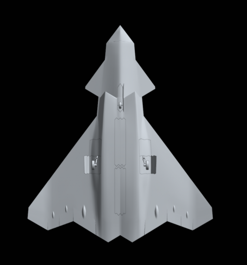
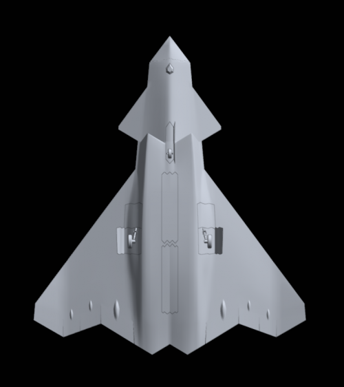
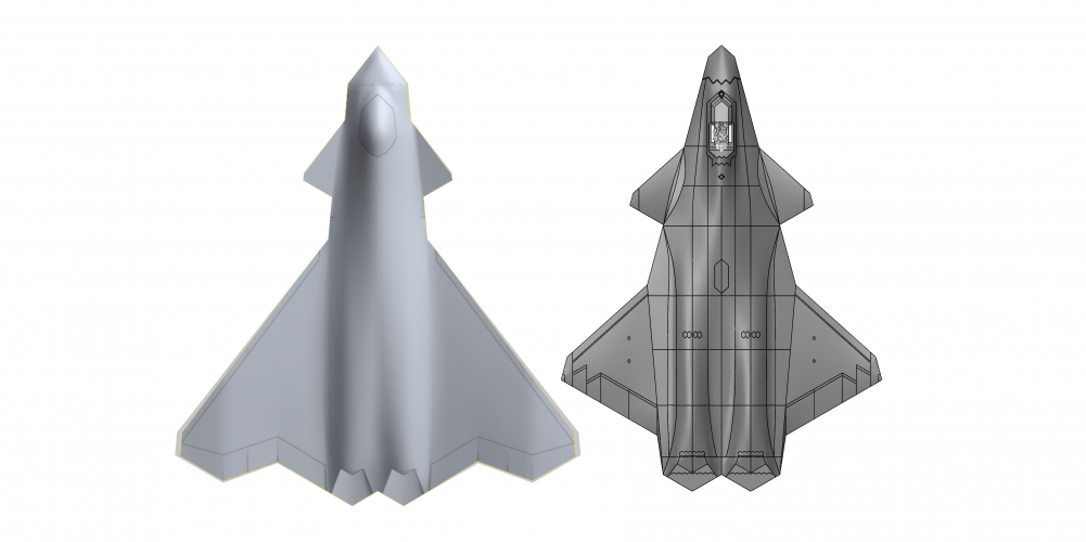
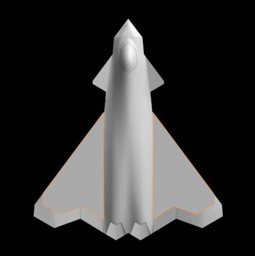
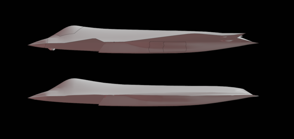
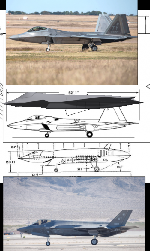
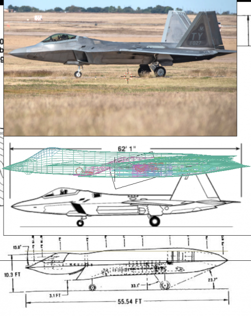
This F-47 version pretty much done. There were some compromises to accuracy around the section between the canard and the wing. Essentially - if I fit one render exactly, I couldn't fit the other render. In the end, I gave up fitting the canard root because that's the most likely area to move / differ. The wing angle is slightly off in the tilted render, but fits the front render. I could only get the cockpit shape to fit a similar area but not the exact shape either.
I'm pretty much done now, and I've come to like this more than my original wide body one.
In case anyone stares long enough, the rear of the cockpit has a shadow that shows the "neck" of the plane curve downwards immediately. So I modeled that accordingly.
Planform & Control Surfaces:
As said before, the wings are at 53 degree wing sweep and so the greater the sweep the less reason I saw to leave room for a straight fuselage and instead used a lambda wing to connect straight to the exhaust outlets. Unlike before, I didn't try to make it match any particular degree, it's just what the perspective matching led me to.
It's supposed to have leading edge flaps, but because the dihedral/anhedral transition, I split the leading edge flaps into 3 parts. Whether that's needed or even reasonable? I have no Idea I'm just a software guy
The trailing edge is supposed to be all control surfaces as well, with split ailerons on the wing tips. The wingtip trailing edge is also supposed to be a control surface. If the aileron root needs to be edge aligned then it could be a bit smaller. If not, then the way I modeled it leaves it pretty large.
I still don't fully understand whether the canard moves and how it moves unless it's moving up and down and not rotating forward or back. My theory is that the LERX and the little gap there shows some kind of movable control surface that either works in tandem with the canards or moves with the canard itself.
Wingspan: 58.1 ft.
Length: 66.1 ft
Wing Aspect Ratio: 2.24
Internal Arrangement:
Engines and Exhaust:
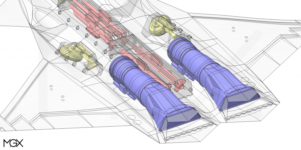
The X102/103 I made measures out to 13.3 ft. There's no good reason or data for me to have chosen the number but it sits between someone's lower estimate of 10 ft and the F119 length of 16 ft. The rest of the dimensions were just scaled off the render PW released (as are the paddles exhausts). The exhaust outlet can probably be even flatter. On the B-21 even the exhaust pipes hide direct view of the fanblades, but there just wasn't enough length to do the same here and I don't know whether it's even feasible for a fighter jet.
Weapon Bays:
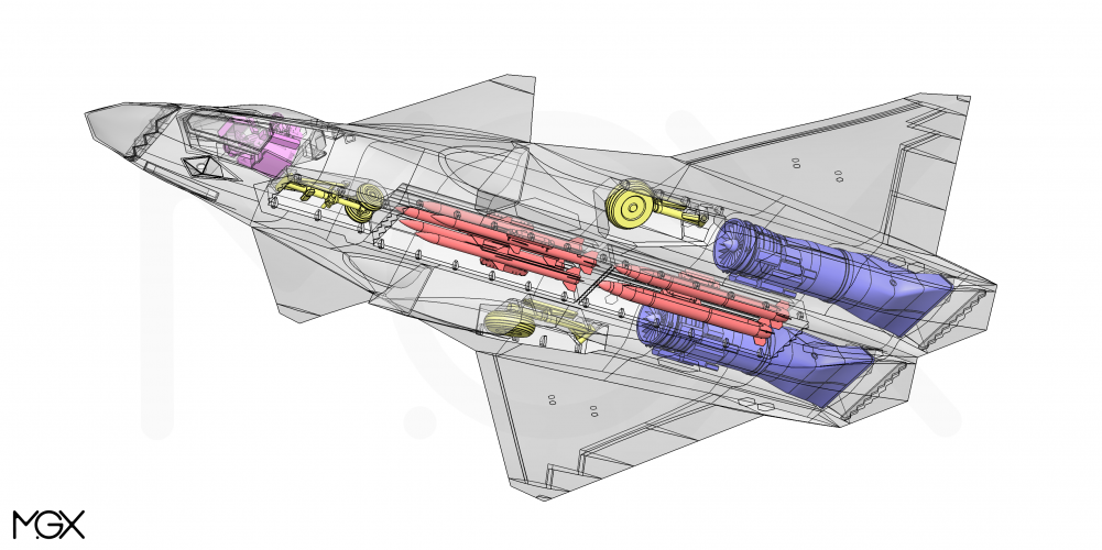
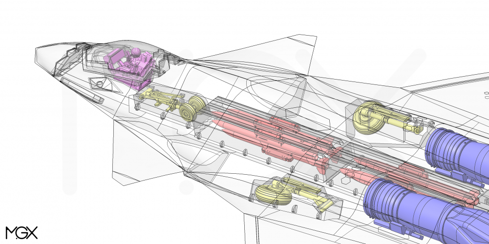
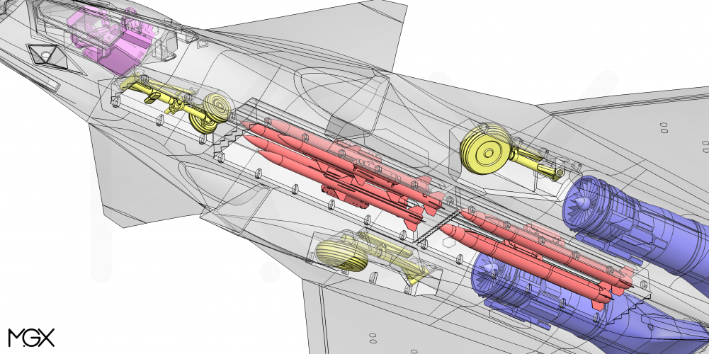
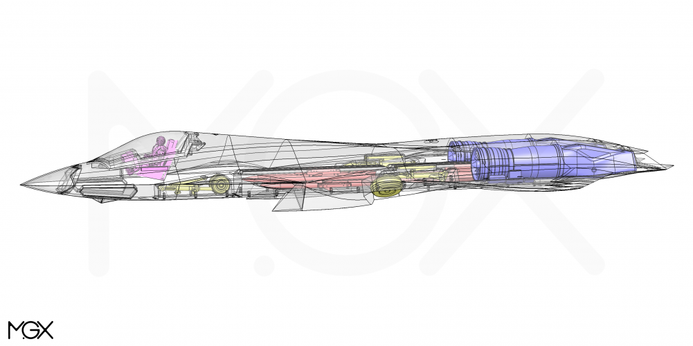
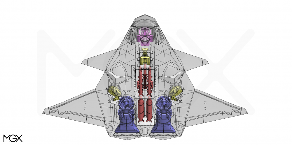
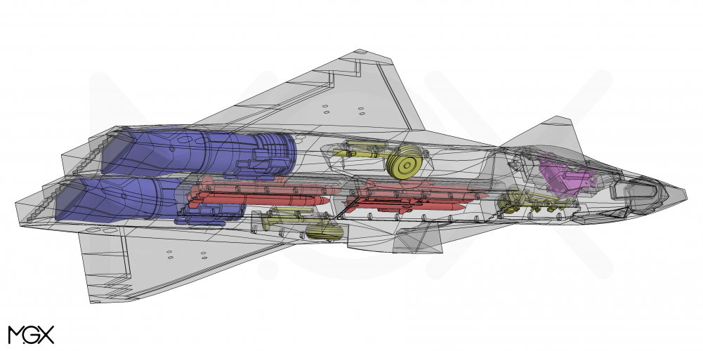
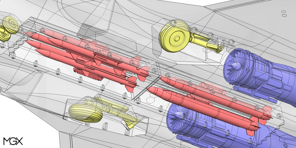
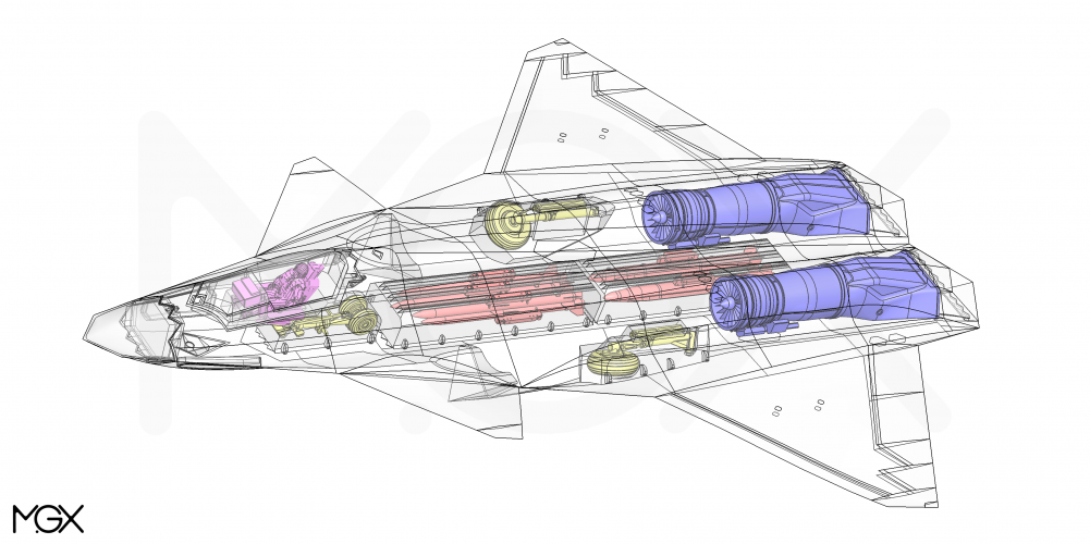
Each weapon bay is 14ft (length) x 3.4ft (width) x 2.5ft (height). The forward weapons bay can probably be deeper but the aft one won't due to fuselage taper. I modeled the AIM-260 and the SiAW (for @Scott Kenny to RIP at night)
All measurements are done including fins:
My AIM-260s are 12.2 ft (l) x 1.05 ft (w) x 1.05 ft (h) modeled from AIM120 sizes
My AARGM-ER are 13.2 ft (l) x 1.37 ft (w) x 1.37 ft (h) modeled from an SiAW image and scaled up according to an F-16 carrying both the SiAW and the AIM120. Could probably be longer.
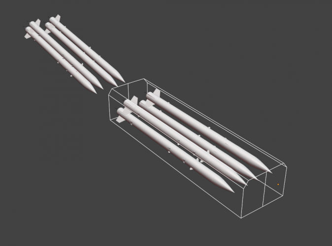
AIM-260's x 8. The top two are hung off the ceiling. The bottom two can either be hung off the side walls or on the weapon bay doors.
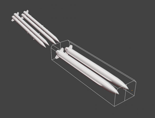
AIM-260's x 4, SiAW / AARGM-ER x 2. Both SiAW/AARGM-ER are hung off the ceiling
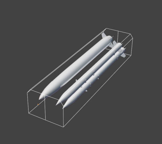
AIM-260 / AARGM-ER 2nd configuration. AIM-260's hung off the ceiling and side.
last but not least, I tried hanging an SiAW on the ceiling and two amraams below it, but because I had to fit the landing gears, the weapon bay correspondingly got narrower. As such, even though it can still fit this configuration, you can't drop the SiAW without firing off the AIM-260s
Sensors
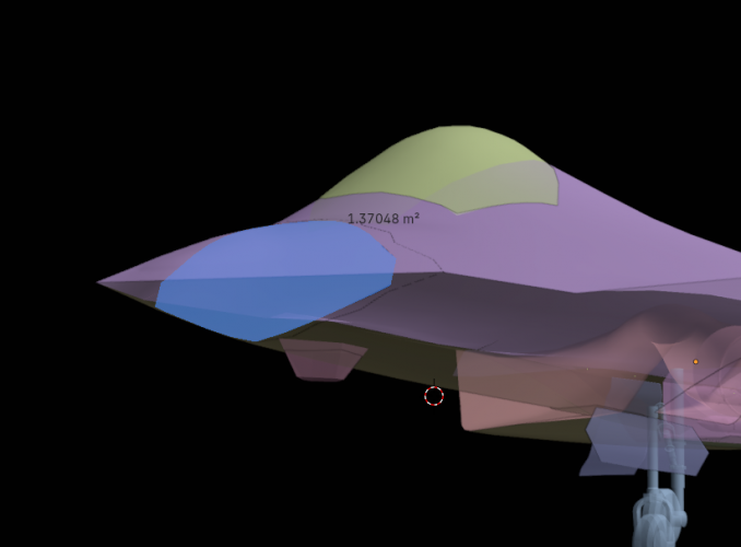
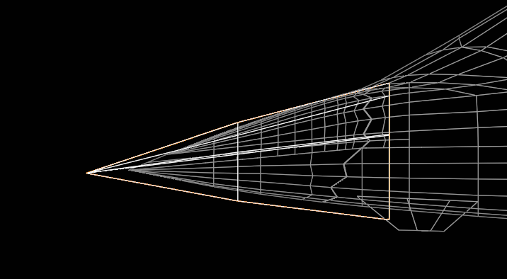
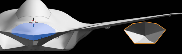
Radome Geometric area measured out to be 1.37 m2. Going with 71% as the ratio between the actual array face and the bulkhead area, then we're at nearly 0.97m2. I also did a radome measurement for the J-36 and the J-36's array face area measured out to be a little over 1m2 so we're at a comparable size here. On previous models, it would have appeared that the aperture area wouldn't nearly be as "tall" as the AN/APG-77's radar aperture, but that's no longer the case.
It could probably have arrays in the wing or on the back as pictured in some twitter posts, but I didn't feel like that needed modeling. As for cheek arrays - I have no idea where that would go. I didn't put it on the bottom of the fuselage because the fuselage is pretty flat and it doesn't offer great angular resolution there. I'm not sure where else I could stick one either. Perhaps it doesn't have any cheek arrays.
I went with a traditional EOTS window.
Wheels
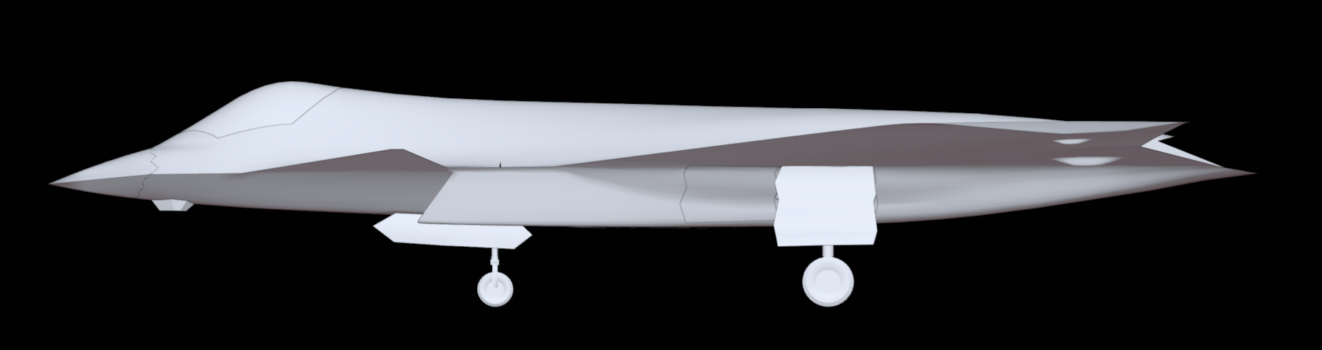
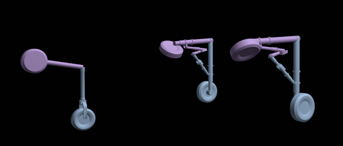
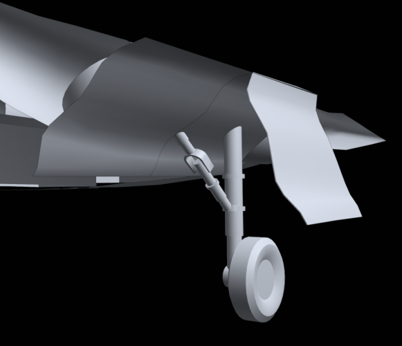
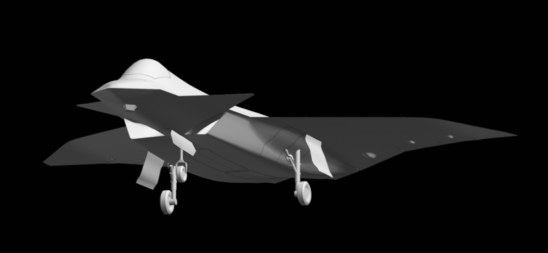
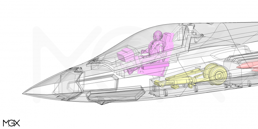
It's all fun and games sticking missiles and bombs into your weapon bays and day dreaming about the kind of fuel this thing can hold until you realize "hey I gotta shove these landing gears into the damn thing" - and then realize all your assumptions were wrong. These landing gears made me hate my life but I managed to fit them.
Please excuse the lego hands - I didn't have the patience to model all the details for the landing gear. For those of you in the know - this is merely for you to determine whether that's enough space to hold a landing gear or not. if not - then those weapon bays are going to be in big trouble.
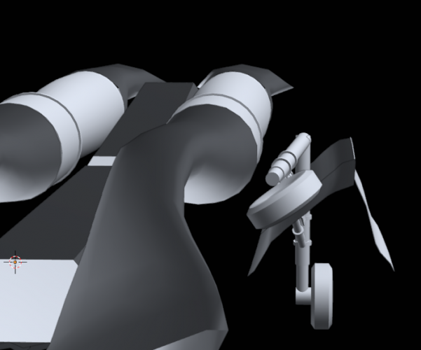
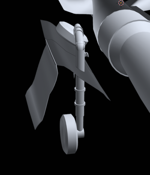
The basic scheme is similar to the F-35 and in some respect the J-20 landing gear. The rear wheels get's pulled up, the wheel twists and gets pulled into the fuselage. I noticed that almost every stealth fighter (except the F-22) has a wing root fairing that store the wheels = F-35, Su-75, J-35, J-XDS all have this fairing. The J-20 also has one but it doesn't store the wheel. Instead, on the J-20, the wheels get pulled up and inwards into the fuselage. This is the scheme I used and in addition to the wing fairing, I think it gives enough space to store the gear.
Here is the clearance between the gear and the engine/intake ducts.
When the wheel begins to swing down, both doors open. Then when the wheel locks into place, the front door closes (I realized I need to make the rear door larger, but that's a fairly trivial change).
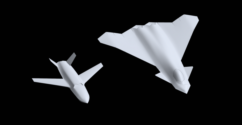
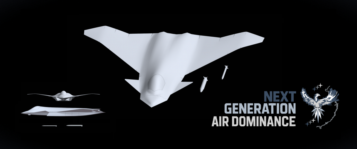
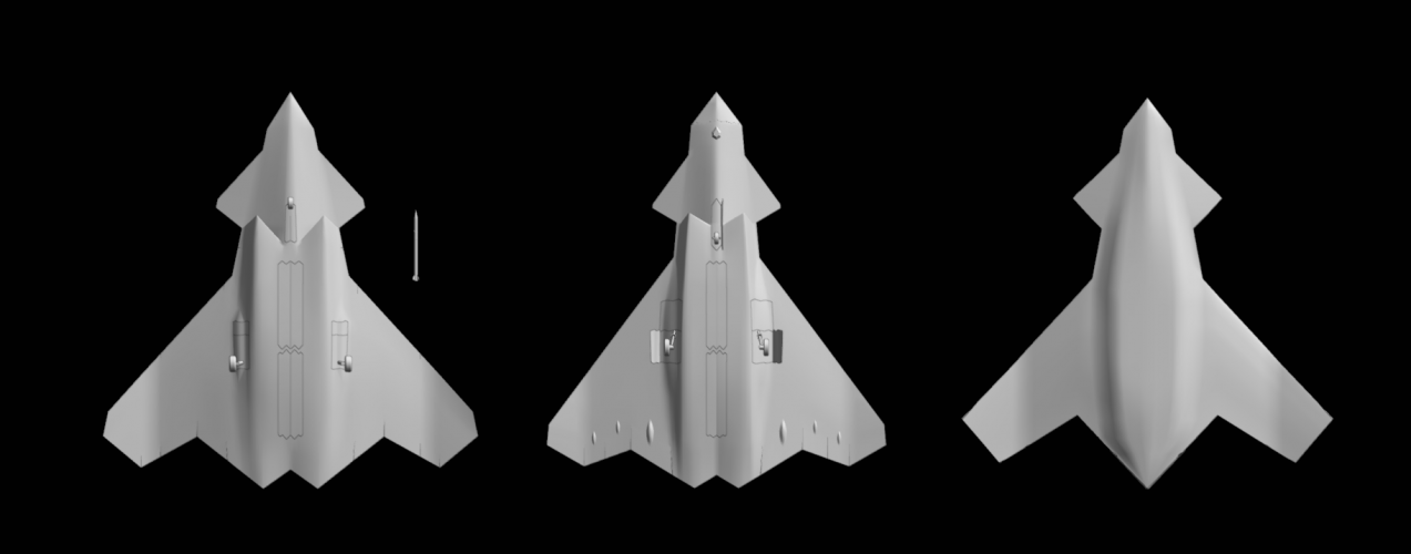
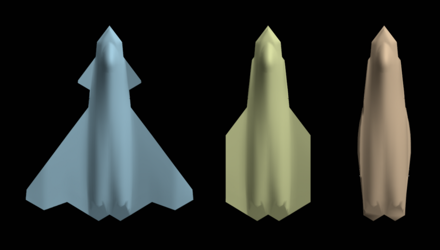
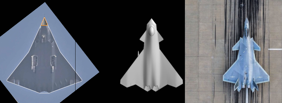
And a comparison with the other two planforms. It's probably clear which one I spent the most time on and it definitely looks more "fighter like" than the wider planform. In hindsight, my wide planform bears some resemblence to Rodrigo's F/A-XX planform.
@Rodrigo Avella You can choose which one you want to render if that's still of interest. I'm still not great at modeling complex geometries and I have yet to find the time to learn how to do animations so all of these models are just models and will require additional UV mapping and animations if you wish to add them. I'll also need to model at least the wheel bays too.
This F-47 version pretty much done. There were some compromises to accuracy around the section between the canard and the wing. Essentially - if I fit one render exactly, I couldn't fit the other render. In the end, I gave up fitting the canard root because that's the most likely area to move / differ. The wing angle is slightly off in the tilted render, but fits the front render. I could only get the cockpit shape to fit a similar area but not the exact shape either.
I'm pretty much done now, and I've come to like this more than my original wide body one.
[...]
Planform & Control Surfaces:
As said before, the wings are at 53 degree wing sweep and so the greater the sweep the less reason I saw to leave room for a straight fuselage and instead used a lambda wing to connect straight to the exhaust outlets. Unlike before, I didn't try to make it match any particular degree, it's just what the perspective matching led me to.
[...]
Wingspan: 58.1 ft.
Length: 66.1 ft
Wing Aspect Ratio: 2.24 View attachment 794645 View attachment 794646
I like this thinner one better, too. As to the "doesn't exactly match either image" problem, like you said you matched the perspectives. And I think that gives us better information.
Still not exactly aesthetically pleasing, but that's not your fault. Blame the Boing engineers!
Each weapon bay is 14ft (length) x 3.4ft (width) x 2.5ft (height). The forward weapons bay can probably be deeper but the aft one won't due to fuselage taper. I modeled the AIM-260 and the SiAW (for @Scott Kenny to RIP at night)
All measurements are done including fins:
My AIM-260s are 12.2 ft (l) x 1.05 ft (w) x 1.05 ft (h) modeled from AIM120 sizes
My AARGM-ER are 13.2 ft (l) x 1.37 ft (w) x 1.37 ft (h) modeled from an SiAW image and scaled up according to an F-16 carrying both the SiAW and the AIM120. Could probably be longer.
AIM-260's x 8. The top two are hung off the ceiling. The bottom two can either be hung off the side walls or on the weapon bay doors. View attachment 794632
AIM-260's x 4, SiAW / AARGM-ER x 2. Both SiAW/AARGM-ER are hung off the ceiling View attachment 794633
AIM-260 / AARGM-ER 2nd configuration. AIM-260's hung off the ceiling and side. View attachment 794634
last but not least, I tried hanging an SiAW on the ceiling and two amraams below it, but because I had to fit the landing gears, the weapon bay correspondingly got narrower. As such, even though it can still fit this configuration, you can't drop the SiAW without firing off the AIM-260s
For the rip, I don't think the strakes are wide enough, unless SiAW has a narrower strake than AARGM-ER does. I think the strakes on SIAW are very close to the same width as the tail fin slant span.
As to the weapons attachment, I think we're looking at the lower AIM260 hanging on the door, not on the side of the bay. Just because that reduces the chances of one weapon hanging and causing problems for others.
It's all fun and games sticking missiles and bombs into your weapon bays and day dreaming about the kind of fuel this thing can hold until you realize "hey I gotta shove these landing gears into the damn thing" - and then realize all your assumptions were wrong. These landing gears made me hate my life but I managed to fit them.
Please excuse the lego hands - I didn't have the patience to model all the details for the landing gear. For those of you in the know - this is merely for you to determine whether that's enough space to hold a landing gear or not. if not - then those weapon bays are going to be in big trouble.
Problem of such very near air intakes : in case of one engine shut off, the air flow is disrupted, and some time at such extent that the other air intake is also impacted.
It was the source of one EF2000 loss, in Spain.
And a comparison with the other two planforms. It's probably clear which one I spent the most time on and it definitely looks more "fighter like" than the wider planform. In hindsight, my wide planform bears some resemblence to Rodrigo's F/A-XX planform.
@Rodrigo Avella You can choose which one you want to render if that's still of interest. I'm still not great at modeling complex geometries and I have yet to find the time to learn how to do animations so all of these models are just models and will require additional UV mapping and animations if you wish to add them. I'll also need to model at least the wheel bays too.
And a comparison with the other two planforms. It's probably clear which one I spent the most time on and it definitely looks more "fighter like" than the wider planform. In hindsight, my wide planform bears some resemblence to Rodrigo's F/A-XX planform.
@Rodrigo Avella You can choose which one you want to render if that's still of interest. I'm still not great at modeling complex geometries and I have yet to find the time to learn how to do animations so all of these models are just models and will require additional UV mapping and animations if you wish to add them. I'll also need to model at least the wheel bays too.
For the rip, I don't think the strakes are wide enough, unless SiAW has a narrower strake than AARGM-ER does. I think the strakes on SIAW are very close to the same width as the tail fin slant span.
Oh yeah please. I've done texturing before but only very basic stuff like loading a .png in as a texture and doing some bump maps on some video game assets. I have some cleanup to do like tidying up some lines and cutting out new weapon bay doors, but I'll link you the blend file after I finish cleanup.
I don't use social media and this is the only platform I'm active on at so Redding777 SPF is probably enough. I'll finish my clean up and share it with you. It's an honor to have you make renders of them!
Also @Rodrigo Avella and @targetpractice I'd love it if you one of you guys could do B-21 colored gray ghost render for me if that's possible. I love that scheme.
Yeah I can change that. It might end up that side by side SiAW just isnt possible and we end up with two AAMs and 1 SiAW per bay.
Oh yeah please. I've done texturing before but only very basic stuff like loading a .png in as a texture and doing some bump maps on some video game assets. I have some cleanup to do like tidying up some lines and cutting out new weapon bay doors, but I'll link you the blend file after I finish cleanup.
I don't use social media and this is the only platform I'm active on at so Redding777 SPF is probably enough. I'll finish my clean up and share it with you. It's an honor to have you make renders of them!
Also @Rodrigo Avella and @targetpractice I'd love it if you one of you guys could do B-21 colored gray ghost render for me if that's possible. I love that scheme.
Congratulations, the resemblance to the official CGI is excellent. Great work!
For a supersonic fighter, this enormous wingspan in relation to the fuselage length might be a bit excessive.
It could be the US equivalent of the J-36, with one engine and one crew member less
Congratulations, the resemblance to the official CGI is excellent. Great work!
For a supersonic fighter, this enormous wingspan in relation to the fuselage length might be a bit excessive.
It could be the US equivalent of the J-36, with one engine and one crew member less
I made it this way admittedly I found it more aesthetically pleasing but also because I struggled with what wing shape it would be if I went with less wingspan.
A delta wing could be possible, but don't know whether that makes sense or not (and it could) with part of the wing being anhedral. The first model I made was a delta wing, but I always thought the anhedral part would be its own wing section with narrow chord length and that working it into delta wings felt strange to me.
I could see having a smaller lambda wing and just doing what you or Rodrigo did though and have similar J-XDS exhausts instead of having the trench exhausts (it's actually what I had on the first iteration too). I don't know whether that introduces a corner reflector or not but it is what it is.
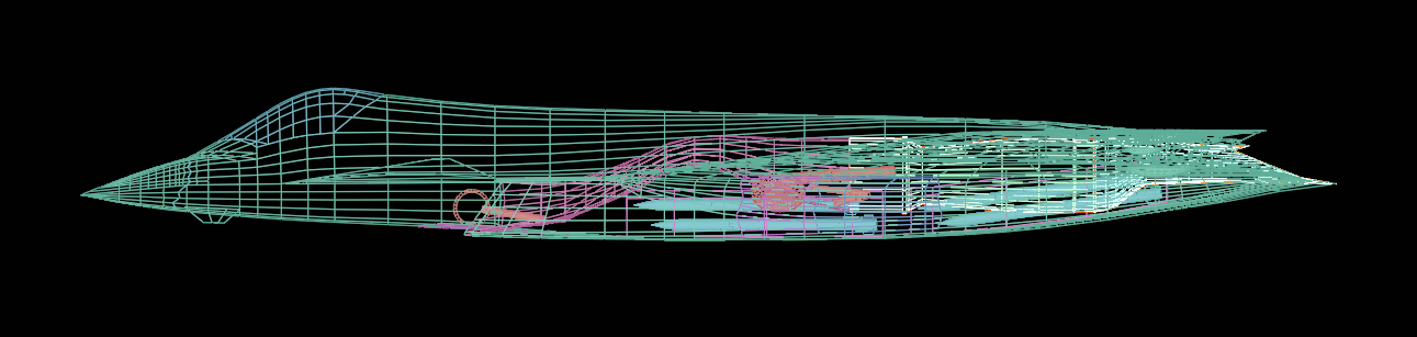
Not sure how you measured your internal volume, but I simply sealed off the model's holes and hit "get volume".
Raw, Wing Trimmed, and Fuselage Only:
Original and Thin (thin is also fuselage only)
- raw: 112m3
- clipped off the wingtip & canard: 107m3
- Fuselage only: 104m3
- Fuselage thin (still fits all the internals) : 98 m3
Compared to yours, that seems like a very high number. Even if we disregard the wings for a second, that fuselage volume by itself is huge even if made thinner. As you can see here, there's a lot of empty real-estate left in the plane although it's unclear to me what else would need to go into the plane and how much of that empty space it would fill. I think if I take out the wing root fairings, I could get down to 80 - 90 m3 but I'm hesitant to go thinner since then the intake ducts would need to flatten and would require more curvature along the width axis - like your model, but that would imply the entire outer mold line needs to be wider and that isn't possible since that part needs to remain perspective matched.
Here's the fuselage comparison with other planes. It does appear that my plane is a little obese but not nearly F-35 level of obese.
I don't have a perspective adjustment of J-XDS though so I can't compare that one.
The J-36 is interesting because in this picture, it doesn't look like the radome is wider than the F-47's radome, but it's substantially more boxy on the lower fuselage.
Not much still. There's still a lot of assumptions being made here (F-22 length, scale of the visible parts relative to the rest of the plane). Even though we've perspective matched somewhat successfully, I can scale the matched part larger or smaller while still maintaining the same perspective match. So really - all the numbers measured here are based off assumptions pinning it to something real (like the length measurement), then working off of that. If it turns out that this plane is an F-35 sized fighter, the numbers change accordingly (substantially smaller radar, less internal volume etc).
The other thing is that there's still stuff not lining up perfectly. The front fuselage should be fairly accurate and any changes won't be substantial enough to make any difference, but the wing angle could be within a difference of a degree or two and consequently anything past that is a toss up.
I made it this way admittedly I found it more aesthetically pleasing but also because I struggled with what wing shape it would be if I went with less wingspan.
A delta wing could be possible, but don't know whether that makes sense or not (and it could) with part of the wing being anhedral. The first model I made was a delta wing, but I always thought the anhedral part would be its own wing section with narrow chord length and that working it into delta wings felt strange to me.
I could see having a smaller lambda wing and just doing what you or Rodrigo did though and have similar J-XDS exhausts instead of having the trench exhausts (it's actually what I had on the first iteration too). I don't know whether that introduces a corner reflector or not but it is what it is.
I always design solid models. This way, SolidWorks can display the body volume directly.
Knowing the volume allows for an estimation of the weight. A density of around 580 kg/m³ seems appropriate to estimate the maximum takeoff weight of a modern supersonic combat jet.
More info here: https://www.secretprojects.co.uk/th...eight-multirole-fighter-lmf.38539/post-507567
Compared to yours, that seems like a very high number. Even if we disregard the wings for a second, that fuselage volume by itself is huge even if made thinner. As you can see here, there's a lot of empty real-estate left in the plane although it's unclear to me what else would need to go into the plane and how much of that empty space it would fill. I think if I take out the wing root fairings, I could get down to 80 - 90 m3 but I'm hesitant to go thinner since then the intake ducts would need to flatten and would require more curvature along the width axis - like your model, but that would imply the entire outer mold line needs to be wider and that isn't possible since that part needs to remain perspective matched.
112 m³ of solid body volume is truly enormous!
For comparison, my model 432 is 77 m³ "raw" (solid model, without any hollow space) and my KF-21 model, based on the KAI three-view drawing, has a volume of 51 m³. I think the F-35 has a volume of around 50–55 m³ and the F-22 around 60–65 m³.
Which brings me back to the topic of density: Ideally, we would know the exact volume of the F-22 (or a similar twin engine stealth fighter) in order to make a good estimate of its density. This would then allow us to obtain a realistic assessment of the weight of our own model.
Model 432 internal layout, length 19.5 m, wingspan 14.0 m, volume 77 m³ ...
This site uses cookies to help personalise content, tailor your experience and to keep you logged in if you register.
By continuing to use this site, you are consenting to our use of cookies.