Now to performance... I'll skip doing the basic requirements since there's little to no change on my end from before.
Some relevant notes on requirements/specification, though:
supermaneuverability: has become basic requirement with the 5th gen superiority but may not hold as much importance with HEL/DEW weapon.
post stall maneuverability: with upcoming Active Flow Control (AFC)(whether bypass air or electric or plasma) will become default regardless of design. Thrust Vector Control (TVC might no longer be needed).

NGAP projection :
since my estimates happens to coincide nearly with DLR-FFD V5 (227 kN) I'm confident it's a 50000 lb class, too
power generation: 338-600 kW total; most likely 400 kW
T/W at GTOW 100000/78571=1.2727
T/W at maneuver weight: 100000/64571=1.5487
T/W at rule of thumb 0.78 GTOW for maneuver weight: 100000/61285=1.63171
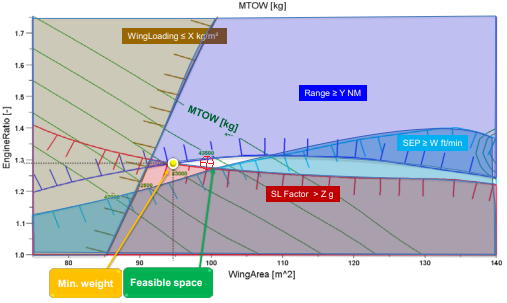
This roughly tracks with similar projections:

fighter-design-constraint-annotated.png
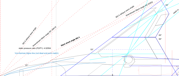
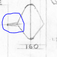
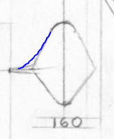
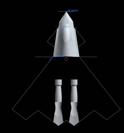
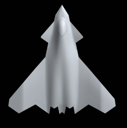
Since my early estimates was higher on fuel than what I see now, I had wanted to raised wing aspect ratio to 3 but it seems 2.8 is the limit. I cheated by making the tip spiky. It looks closer to the J-50 now... but the J-50 has AR2.5 and double the wing area! The J-50 should be able to pull higher g-forces at high mach speeds.

wing-AR2.8.png

Anyhow my slightly improved fuel calculation clearly point to the possibility of a "smaller" airframe. I could make it more precise but it won't be too different to make it worth trying.
old:
strike mission 27108.24 lb fuel
CAP 25622.24 lb fuel
reserve 1702 lb fuel

new:
strike mission 18085.54 lb fuel
CAP 18823.65 lb fuel
reserve 2889.92 lb fuel

To other minor specs just to make it complete.
Systems:
avionics (helmet brain interface, comms, radar, EW, sensors etc.):
today: min. 200 TIPS, min. 30-40 POPS, min. 400 PFLOPS FP64, 400 TB, 0.12-6 TB/s, ~1 m³, 15 kW
(note: production version will be available at a later time ~5 years, hence, could be ~10-100x better)
(if using photonic 1000x uplift at 1/100x energy but will be limited to some use cases due to size)
thermal load:
• idle: 50 kW
• supercruise: 170 kW
battery: min. 300 Wh
E-HEL/DEW (volume worse than a gun+1000 rounds):
• 100 kW: minor impact to thermal load
• 600 kW: requires capacitor charging and min. ~10.8 kg/min. expendable liquefied natural gas (LNG) coolant at 0.45 kg/L => 24 L tank
 
NGAP projection :
since my estimates happens to coincide nearly with DLR-FFD V5 (227 kN) I'm confident it's a 50000 lb class, too
power generation: 338-600 kW total; most likely 400 kW
I would guess the upper limit of this power generation is more likely, a single F135 holds 160kW and the japanese were able to pack 360kW with their considerably simpler "5th gen" engine
 
It depends on thrust trade-off or what the USAF plans to have for HEL/DEW.
The lower limit is basically "free" and no different from current trade-off. While my higher limit is based on generator size that could fit inside. The chinese appear to want 1 MW as the starting point and this seems due to them planning to have use two generators inside
 
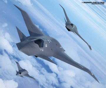
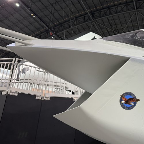
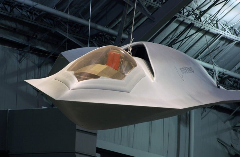
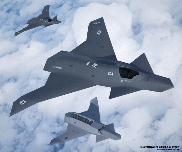
Not really a beauty with that donald duck nose and that bulky underside.
It looks more like repelling the ground then flying
Hi!

I'm taking some more pictures of this model to post here.
I don't think it's very pretty either, haha.
I'm in contact with some engineers from Lockheed and Northrop, and they both agree that Boeing's plane won't be very aesthetically pleasing. Or at least that's what they think, based on Boeing's design philosophy.
Sorry if any Boeing engineers are reading this comment. I know I'm nobody to give an opinion like this, but that's what they told me about the competing companies, haha.
In this model, I think the canards are too far back. They should be a little further forward.
On the other hand, the F47 will surely have a 360-degree DAS systen, because the downward view with the canards in that position is practically nonexistent.
Best regards!
 
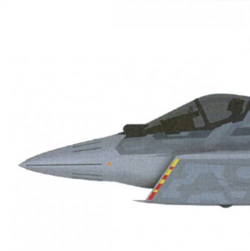
I think there is great beauty in this design considering the practical implications of key design parameters. The shovel nose harboring a larger effective surface for forward directed TRM arrays being just one small example. For someone like me who has spent way too much time poring over the ICE, FWV, JAST etc bodies of work, I find your design very gratifying.
 
Or at least that's what they think, based on Boeing's design philosophy.
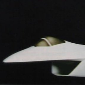
I think you captured some of the essence of advanced Boeing proposals and demonstrators quite well. The intake especially screams Boeing ATF and X-32. However I'd expect the intake to have a...backward slant(?), more so than slanting forward like in your artwork. Purely based on the designs from Boeing as well as other aircraft with similar intakes and DSI intakes in general. I think the nose and wing arrangement is spot on in terms of public renderings and demonstrators like the Bird of Prey or X-36.

IMG_20251119_154522.jpg IMG_20251119_154649.jpg IMG_20251119_154604.jpg IMG_20251119_154625.jpg IMG_20251119_154714.jpg
 
Darold Cummings posted a F-47 concept about a month ago... haven't seen it on this thread yet. Thoughts?
https://www.linkedin.com/posts/daro...odification-activity-7384680509412401152-gZl8
1760645032265

1760645008242

1760645011440
 
Last edited:
@Seragina Regarding the 52 degree wing sweep, that's the sweep for a mach 1.6+ regime, but wouldn't that mean less efficient flight in the speeds up to mach 1.5 - 6 ish where you'd be spending the majority of your supercruise flight + BVR fighting at? Also - there are canards on this fighter which would need a leading edge sweep matching the wing sweep. I would think something like mid 40's sweep would be good enough but I'd love to hear your (and others) thoughts on that.

@Rodrigo Avella , how do you envision the intake airflow will be split here in your ventral intake models?

With such a large weapon bay, where is the landing gear placed?
This is actually what caused me great headache when trying to fit a single central intake.

Arguments against a ventral intake:
  1. Primarily, the reason for this is that we know it's a twin engined fighter. Every single example of a ventral intake proposed for a stealth fighter (of which there are extremely few) also only feeds a single engine and thus doesn't need a split airflow. For this and other ventral intake renders, I'm curious in this render how you've split the airflow. Last I asked about this, it was said that you need to split the airflow upfront rather than internally - a splitte plate like the Su-75 or Eurfighter kind, but that's now somewhat problematic RCS wise. The Su-75 remains the only stealth fighter with a splitter plate looking thing in it's intakes (even though it's been said that that isn't a splitter plate either).
  2. Tangentially, landing gear placements and internal volume also don't lend itself to this. Looking at the few examples we have of fighter aircraft with ventral intakes, the front landing gear is always sitting on the ventral intake itself - I presume due to creating turbulent air and kicking up debris if it sits in front of the intakes. That means:
    1. Your intakes must sit further forward and the narrowing of the fuselage also begins to constrict the intake area, which, from what's been discussed on this forum, should be generally wider than other stealth fighter intakes due to VCEs
    2. The other option is to have a much longer fuselage to allow you to put your ventral intake and front landing gear further back while still having large bays, but then we aren't talking about an F-22 or YF-23 sized fighter.
    3. A wider or thick airframe. In this configuration, I couldn't fit tandem bays in my model because that interferes with the front wheel bay position. Going with a side by side bay configuration couldn't fit nearly as many weapons.
 
Last edited:
It was twin engined EmoBirb, that is what caught me of guard when I saw it in Bill Sweetman's F-22 Raptor book back in 1998 when the Boeing X-32 was in the JSF. By the way it finnished third in the downselect back in 1986 ahead of McDonnel Douglas's proposal, just behind Northrop-Grumman.
 
Boeings ATF proposal looks twin engine to me
Yeah - I referenced that when working on my model too, but this concept doesn't show anything regarding how the airflow may be split.

Is a splitter plate placed diagonal (edge aligned with the lip of the intake) bad for RCS? I mean from past discussions on this, there doesn't seem to be another viable way to split the airflow. Apparently splitting it internally isn't an option due to turbulent flow. Splitting it with a DSI makes no sense at that point as there's no reason not to just use the fuselage to split intakes into two intakes - thereby giving greater internal volume and a much larger radome.

Also not totally sold on the long and narrow fuselage shape. I think both renders show a more tapered forebody though not as much as the Chinese 6th gens due to having a wide chisel nose. I'm not sure about wing aerodynamics, but there seems to be little good reason to inroduce further corner reflectors on the rear of the plane. Might as well make the aft wing root extend to the engine exhaust lip.
 
Last edited:
Darold Cummings posted a F-47 concept about a month ago... haven't seen it on this thread yet. Thoughts?
Well for one ... it has basically zero commonality with those renders. But it does look like something lockheed would come up with, as the inspiration here is pretty clear.

Also a lot of these drawings and renders (though not usually the ones posted here on this forum) have another problem - If you're going to have a double delta, or any chined platform for that matter, the whole point is to take advantage of the added area for internals - whether that be bigger sensors or a more fuel.
1763584464684.png 1763584564837.png

If you thin out the majority of that planform just to fill the "shape", beyond a certain point it's just a waste of what could be ample real-estate. This isn't a B-21 where thanks to its size, things that look thin aren't really that thin.

I don't know if anyone's noticed, but the front view render of the F-47 - the chines are more or less set at the same angle as the natural contour of the radome. There's no significant thinning or pinching for the chine. It doesn't mean there's fuel or something there, but it's incidence allows the pinching to happen at the chine while giving much greater area for the radome. When I was modeling, just correcting the incidence of the chine increased the radome cross sectional area by something like 15%.
 
Last edited:
I mean from past discussions on this, there doesn't seem to be another viable way to split the airflow. Apparently splitting it internally isn't an option due to turbulent flow.
I could imagine that, depending on how much volume you have to work with and how far "up" you pull the intake like (like the X-32) that there are ways to either position a splitter deeper in the intake or at least obscure it more, in conjuction with liberal use of modern day RAM I could imagine that it's possible to pull it off these days but maybe not back then.

Alternatively an intake design like on Shenyangs next generation fighter may have been considered. Which looks to be some sort of hybrid of DSI intake and essentially an underbody intake seperated by the forward fuselage.

I personally doubt that we'll see caret intakes, as seen on the F-22 and the very first J-36 prototype. Some sort of DSI is probably what they ultimately went with and patents, rumors and looks at the chinese jets may all hint at the idea of a variable divertless supersonic intake. Whatever it is, they surely knew to obscure it on official renders, so I expect it to be either novel (variable DSI) or unconventional ("pelican" style intake).
 
Last edited:
It was, and that was also a strike against it. If you look at things like the Typhoon, NA F/X, MiG 1.42, they all split the duct from the get-go.
Surely, but these are obviously largely 80s designs, modern software and material science may give Boeing the opportunity to go with the intakes they favored all these years back. But I personally know better than to lean solely on that possibility, given that Boeing (and MDD) stuff like the BoP or X-36 feature other configurations and were viable and advanced technology demonstrators.

I think the intake(s) and nozzles will definitely be the most intriguing aspects of the airframe itself, everything else is kinda irrelevant given the distributed system that's being set up through the NGAD program (screw payload when you can simply load up drones, or distribute your sensors that way).
 
1763589475214.png
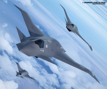
@Rodrigo Avella THERE SHE IS! Superb job. Shovel nose and everything, she's beautiful.

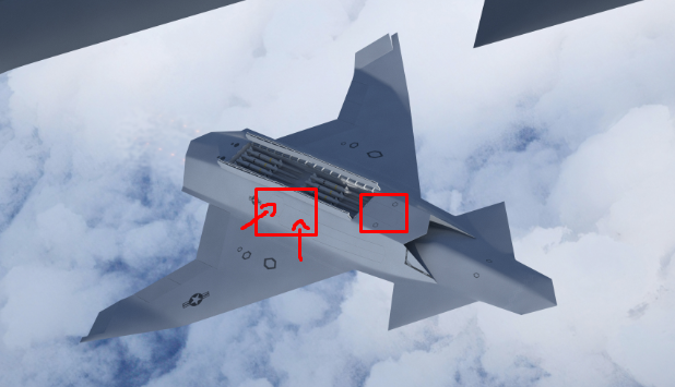
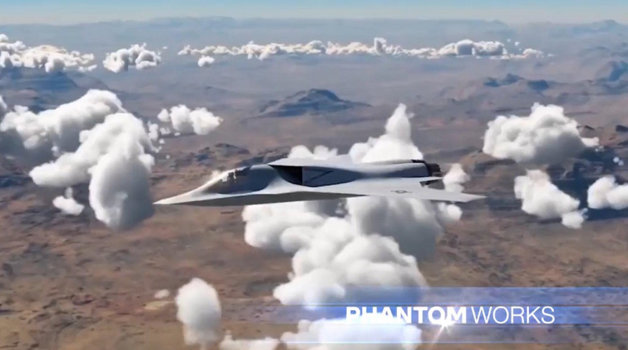
To me, the only factors left to question are whether the obvious image doctoring on the rear of the plane on the F47 press release are meant to occlude a dorsal intake versus ventral intake, as present on a few of the Phantom Works NGAD concept art images. Case in point:

1763589582264.png

And of course, whether the front canards are there for smoke and mirrors, and we should expect some strong chines or even LEVCON-like surfaces directly behind the nose instead, and coincidentally... Similarly to the render I just posted. Although with the wing sweep close to the center of thrust the canards may be necessary to move the center of lift forwards.

Those two elements I think we will only find out when she is finally revealed.
 
dorsal intake versus ventral intake
In the render you posted, you can see roughly where the dorsal intakes are relative to the rest of the plane.

The tilted render is where you can see pretty far back along the fuselage. You can see far back enough to where the wings have already started. Putting two and two together, if there weren't visible intakes that far back then I doubt there's going to be dorsal intakes at all.

Assuming the renders aren't bs...

Also that particular phantom works render always reminds me of:

1763591951654.jpeg
Or alternatively:
1763592271433.jpeg

F-47 platypus doesn't really inspire fear though...
 
Last edited:
Also a lot of these drawings and renders (though not usually the ones posted here on this forum) have another problem - If you're going to have a double delta, or any chined platform for that matter, the whole point is to take advantage of the added area for internals - whether that be bigger sensors or a more fuel.
1763584464684.png
1763584564837.png


If you thin out the majority of that planform just to fill the "shape", beyond a certain point it's just a waste of what could be ample real-estate.

But from a transonic / supersonic drag perspective, filling out those chines must really hurt the fineness ratio of the forward fuselage and create a lot of drag, no?

If you look back at the McDD studies from the 1990s (2408, 2409 etc), they most definitely had the same "thinned out" shape around the chines...
https://www.secretprojects.co.uk/th...ration-synthesis-study-1994.45200/post-746322
291735-779956bf4226b789a6ccf19453d0a590.jpg
 
But from a transonic / supersonic drag perspective, filling out those chines must really hurt the fineness ratio of the forward fuselage and create a lot of drag, no?
I'm not terribly well informed about this either, but you should still be able to stay wide/thick as long as the incidence that leads to that width/thickness isn't abrupt with respect to the airflow. So as long as your nose, cockpit / forward facing surfaces remain shallow in incidence, those side chine thickness/thinness shouldn't (in theory) be too problematic.

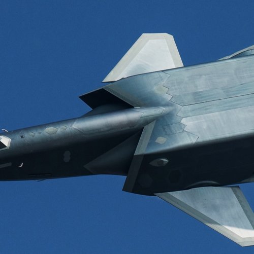
Take the J-36 or the Su-34 for example - they have extremely wide cockpit and nose section. That does cause a lot of dra, but that's partially mitigated through a shallow incidence with respect to airflow:
1763599533023.png 1763599560844.png

If you look back at the McDD studies from the 1990s (2408, 2409 etc), they most definitely had the same "thinned out" shape around the chines...
https://www.secretprojects.co.uk/th...ration-synthesis-study-1994.45200/post-746322
That is true, but in those MDD designs, if you look at the contours, you can see even the cockpit width changing along side the chine width to take greater advantage of the chine's widening. The chines also do not pop out as much or as sharply. It's actually the combination of two things that a lot of designs don't get - if your chine is expanding towards the fuselage, the rest of the contours generally expand as well and that includes the width of your cockpit.

So to have an F-22 shaped fuselage cross section with a sharp chine makes no sense.
1763597338019.png


Actual aircraft that flew pretty much did not have chines that thin, sharp or pop out as far from the fuselage. Almost always, the shape of the cockpit / fuselage useful volume also expanded along with the chine as you moved toward the wing root. You can tell from the YF-23 how the shape of the cockpit and spine also expands as we move towards the wing. This same pattern repeats on the F-35 and F-22 designs too. Both Chinese fighters have chines but they also aren't sharp either and their cockpit / fuselage width takes good advantage of the chine.
1763597045686.jpeg 1763596879861.png 1763599029342.jpeg
Even something with chines as sharp as the bird of prey - they quickly expand instead of forming control surface like thickness (or thinness). The cockpit is also really wide and that allows non-cockpit fuselage to have greater volume. This is also on a plane that doesn't need to worry about internal volume as much. On the YFQ-42, the chines expand even faster and they just barely taper. You want the chine to mostly compensate for the tapering - not taper the actual useful volume significantly to accommodate a thin chine.

In contrast:

1763598842643.jpeg

The cockpit is incredibly cramped and narrow where if it were wide at the base, you'd have at least double the radome cross sectional area. Probably also smooth the spine with the start of the engine nacelles too.
 
Last edited:
@Seragina Regarding the 52 degree wing sweep, that's the sweep for a mach 1.6+ regime, but wouldn't that mean less efficient flight in the speeds up to mach 1.5 - 6 ish where you'd be spending the majority of your supercruise flight + BVR fighting at? Also - there are canards on this fighter which would need a leading edge sweep matching the wing sweep. I would think something like mid 40's sweep would be good enough but I'd love to hear your (and others) thoughts on that.

@Rodrigo Avella , how do you envision the intake airflow will be split here in your ventral intake models?


This is actually what caused me great headache when trying to fit a single central intake.

Arguments against a ventral intake:
  1. Primarily, the reason for this is that we know it's a twin engined fighter. Every single example of a ventral intake proposed for a stealth fighter (of which there are extremely few) also only feeds a single engine and thus doesn't need a split airflow. For this and other ventral intake renders, I'm curious in this render how you've split the airflow. Last I asked about this, it was said that you need to split the airflow upfront rather than internally - a splitte plate like the Su-75 or Eurfighter kind, but that's now somewhat problematic RCS wise. The Su-75 remains the only stealth fighter with a splitter plate looking thing in it's intakes (even though it's been said that that isn't a splitter plate either).
  2. Tangentially, landing gear placements and internal volume also don't lend itself to this. Looking at the few examples we have of fighter aircraft with ventral intakes, the front landing gear is always sitting on the ventral intake itself - I presume due to creating turbulent air and kicking up debris if it sits in front of the intakes. That means:
    1. Your intakes must sit further forward and the narrowing of the fuselage also begins to constrict the intake area, which, from what's been discussed on this forum, should be generally wider than other stealth fighter intakes due to VCEs
    2. The other option is to have a much longer fuselage to allow you to put your ventral intake and front landing gear further back while still having large bays, but then we aren't talking about an F-22 or YF-23 sized fighter.
    3. A wider or thick airframe. In this configuration, I couldn't fit tandem bays in my model because that interferes with the front wheel bay position. Going with a side by side bay configuration couldn't fit nearly as many weapons.
One problem with an inlet internally split between two engines is that a compressor stall on one engine can disturb the airflow to the other engine, resulting in a double engine stall. Not saying it can’t be done, but this tends to interfere with the redundancy provided by two engines
 
One problem with an inlet internally split between two engines is that a compressor stall on one engine can disturb the airflow to the other engine, resulting in a double engine stall. Not saying it can’t be done, but this tends to interfere with the redundancy provided by two engines
Are there any better reasons for having a single ventral intake over two ventral intakes or more conventional side intakes? There's a lot of cons against having a ventral intake but I haven't heard any other arguments for having a single ventral intake.
 
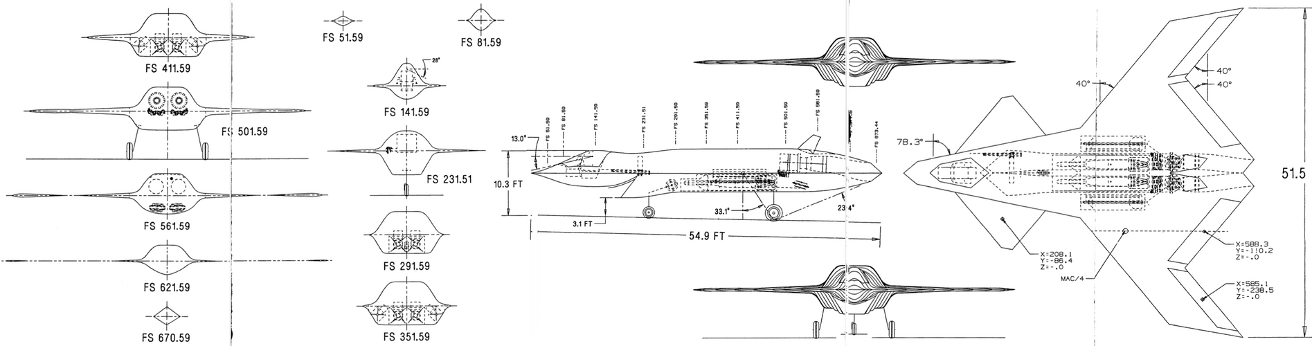
So the second one is actually from NG presentation. Maybe it has to do with their submission for NGAD or FA-XX or both?
 
Not without surprise it looks like that NG PPT is from 2024. Has anyone done artwork of the configuration depicted? Apart from being in a NG PPT, that configuration gives an uncanny vibe of actually fitting overall with what little we've seen from F-47 renderings so far.
 
Not without surprise it looks like that NG PPT is from 2024. Has anyone done artwork of the configuration depicted? Apart from being in a NG PPT, that configuration gives an uncanny vibe of actually fitting overall with what little we've seen from F-47 renderings so far.
Depending on how close you want to get to the two official renders, @Seragina's looks pretty close.

I also made one that I haven't posted these because, well it doesn't really bring too much new to the table, but this is at 52 degrees LE sweep (the WIP one) and 49 degrees LE sweep:
1763666092442.png 1763665961421.png

Apart from the cockpit, wing sweep and nose shape though, a lot of the other features in the PPT doesn't match the official renders.
 

Similar threads

Back
Top Bottom