During the interwar period, carrier-based fighter designers did not introduce major innovations, all naval fighters were biplanes with open cockpits, fixed landing gear, radial engine, fuselage structure made up of metal tubes, wooden wings and fabric covering.
The British began using flaps on the Fairey Flycatcher to reduce take-off and landing distances as much as possible, they also introduced the use of V-12 engines in the Hawker Nimrod and stainless-steel structures in the Hawker Osprey, but when it came time to use monoplane fighters, the Fleet Air Arm ran into the problem that the carriers of the Illustrious Class had been designed with elevators that were too small to accommodate only aircraft with folding wings.
When the Second World War began, it was necessary to hastily navalized 98 Gloster Gladiator Mk. II biplanes, which had been built for the RAF, until folding wing Fairey Fulmars became available in July 1940.
Nor had American naval fighters evolved much since the Boeing F4B entered service in 1933, the introduction of a supercharger in the F4B-3 version did not improve its acceptance aboard the U.S.S. Saratoga and the model was eventually transferred to the U.S. Marines.
The Curtiss F11C/BTC-2, fitted with semi-enclosed cockpit canopy, was also not very successful, and was used as a fighter-bomber in the U.S.S. Saratoga and the U.S.S. Enterprise between 1933 and 1938.
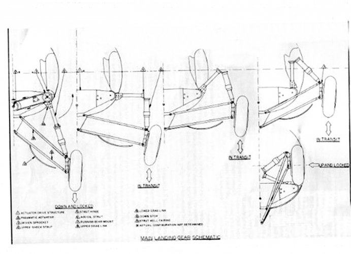
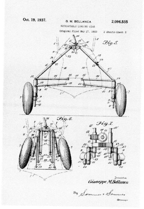
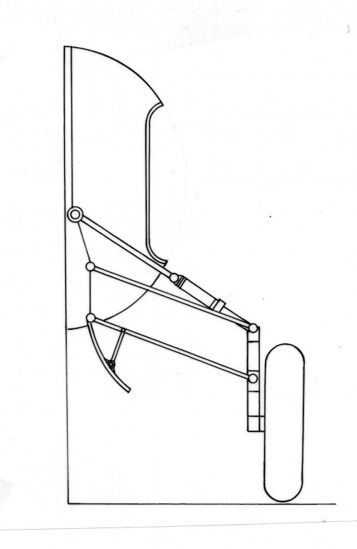
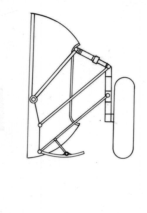
In 1934 operational tests began on the BF2C-1 version, equipped with Dayton-Wright retractable landing gear, but this innovation created many problems along with the timber and metal mixed structure wing construction system, the model was only in service for a few months.
At that time, the use of retractable landing gear in naval aircraft was not due to the need to increase speed, because they were all biplanes, but to the problem of quickly sinking in an inverted position when an aircraft with a fixed gear tried to splash down in an emergency, making it difficult for the pilot to evacuate.
In 1933 the Grumman FF-1 entered service equipped with a new type of retractable gear, developed by Loening, which was safer than that used by the Curtiss BF2C-1, and with a new hydrodynamic belly designed to facilitate aquaplaning maneuver.
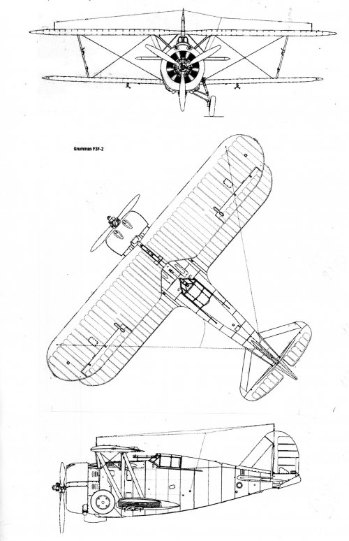
This innovation was a success, and the U.S. Navy ordered two new biplane fighters with enclosed cockpit hoods based on the FF-1 formula, the Grumman F2F-1 (1935-1940) and the Grumman F3F-1 (1936-1940).
But in 1937 the rules of the game changed drastically with the entry into service of the Mitsubishi A5M, a Japanese low-wing monoplane that saw combat in China.
The A5M surpassed everything the Chinese threw at it:
-Biplanes with fixed landing gear Curtiss Hawk II, Gloster Gladiator Mk. I, Polikarpov I-152 and Fiat CR.32.
-Biplanes with retractable landing gear Curtiss Hawk III and Polikarpov I-153.
-Monoplanes with low wings braced and fixed landing gear Boeing Model 281 and Breda 27.
-Monoplanes with cantilever wings and fixed landing gear Dewoitine D.510 and Curtiss Hawk 75 M.
When intelligence services began reporting the successes of the A5M, Western designers did not believe that it was possible to build a fighter with such performance and maneuverability using the technology of the time because until then Japanese designers had limited themselves to copying Western designs such as the Boeing Model 100 and the Hawker Nimrod.
The reality was that the A5M had originally been designed as a land-based naval fighter for the war in China, but the extraordinary lightness of its aluminum construction and the use of powerful engines allowed it to take off and land from the Hosho Class aircraft carriers.
Since 1932, French designers had been experimenting with high-wing monoplanes for the aircraft carrier Béarn. The Wibault 74 naval fighter entered service in 1932 and was replaced by the flap-equipped Dewoitine D. 373 in 1934.
The high-wing fighters had exceptional STOL qualities and were ideal for use on aircraft carriers, but their maneuverability was poor, and they could not compete with low-wing monoplanes.
During the second half of the 1930s, the rise of aggressive dictatorships produced new designs of fast monoplane bombers that posed a very real threat to Allied aircraft carriers.
In 1936 a Heinkel He 111 airliner made a demonstration flying at 402 km/h, in 1938 the He 111 E-1 combat version reached 420 km/h with bomb loading and was impossible for the Spanish Polikarpov I-16 to intercept.
In August 1937, the Japanese land-based naval bomber Mitsubishi G3M entered service with 4,400 km range, 9,200 m service ceiling and 375 km/h top speed.
A year later, Chinese fighters Curtiss Hawk III and Boeing 281 discovered that they could not intercept the new Imperial Japanese Army Mitsubishi Ki.21 bomber with 10,000 m ceiling and 485 km/h top speed.
In September 1939 the Junkers Ju 88 A-0 heavy dive bomber, with 450 km/h and 8,000 m ceiling, entered service.
To make the situation even worse, Germany and Japan began developing carrier-based dive bombers.
In September 1939 the Junkers Ju 87C, the navalized version of the Stuka with 382 km/h and 7,000 m ceiling, entered service, in November it was followed by the Aichi D3A with 450 km/h and 8,000 m.
Fortunately for the Americans, the Essex Class aircraft carriers had no size problems in the elevators (18 x 20 m) and could operate with monoplanes.
The design of naval fighters with retractable landing gear was no longer oriented towards aquaplaning but towards reducing drag to increase speed.
At the end of 1935, the U.S. Navy Bureau of Aeronautics issued a specification calling for a 300-m.p.h. carrier-based single-seat fighter as replacement of the obsolete biplane F3F.
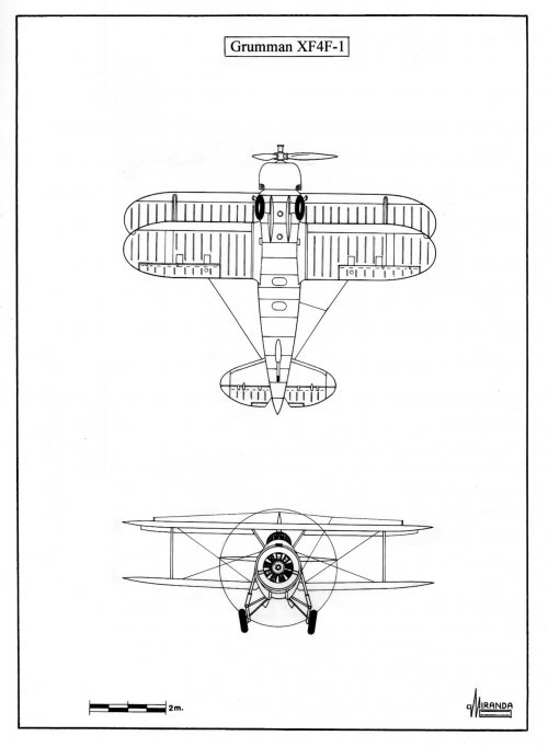
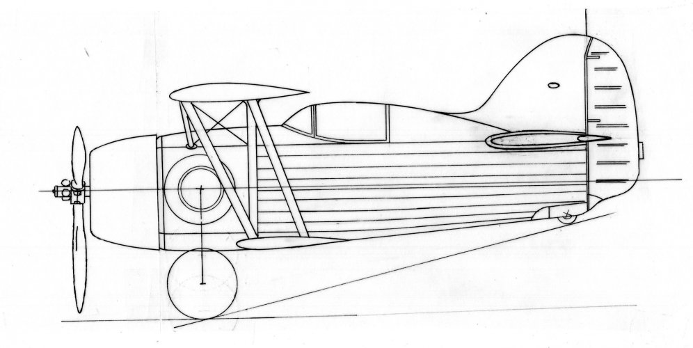
The Grumman Company proposal was the Model G-16 which was a F3F extensively modified with Loening manually operated retractable landing gear.
To improve performance, the designers decided to use a P&W R-1535-94 engine with a smaller diameter of 207-mm than the Wright R-1820-22 used in the F3F, they also reduced the wingspan by 1,520-mm and the maximum weight by 203 kg.
To compensate for the decrease in wing surface, it was decided to install large flaps on the upper wing.
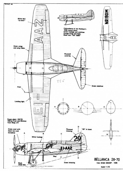
Several designs were also submitted by Bellanca, Brewster, Curtiss, Seversky and Vought.
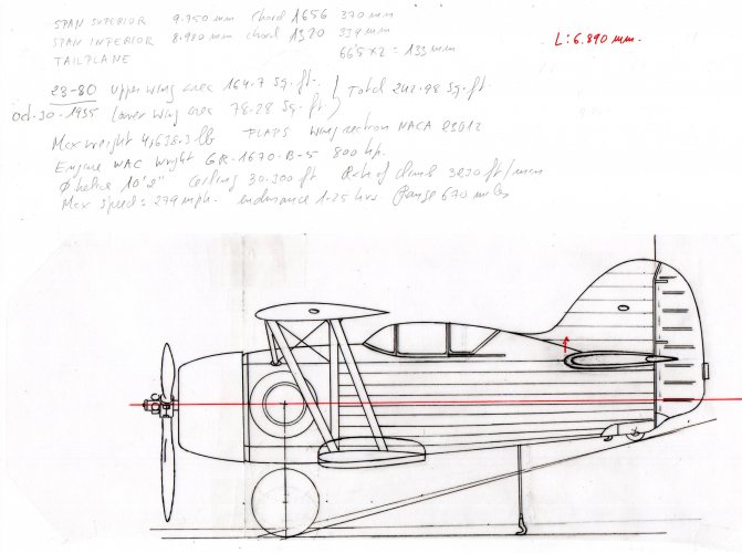
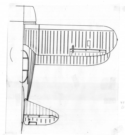
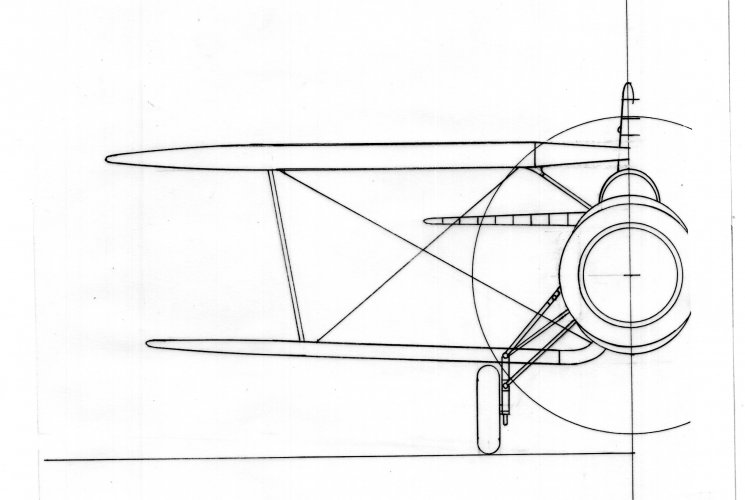
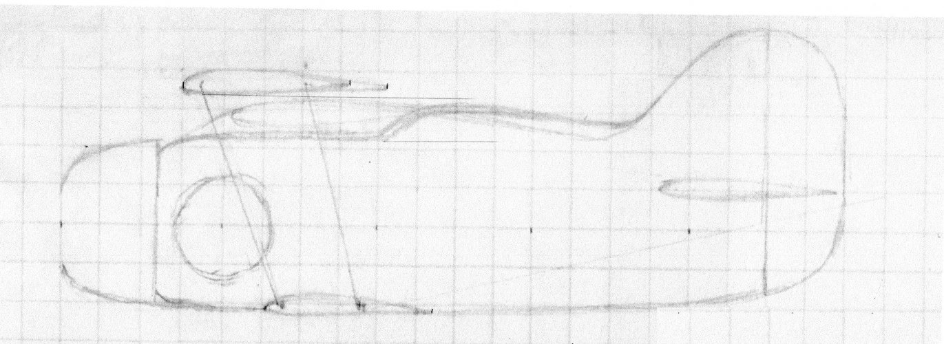
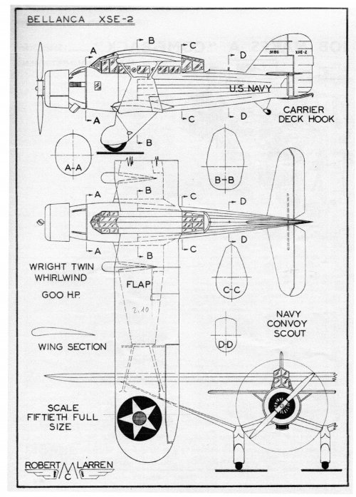
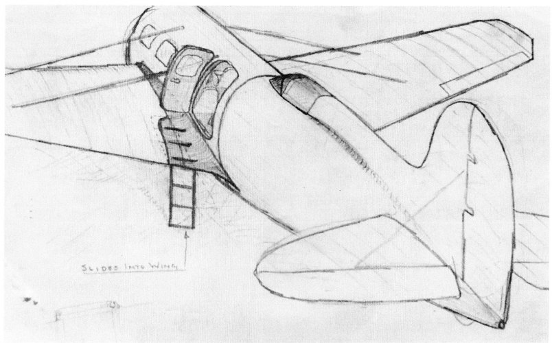
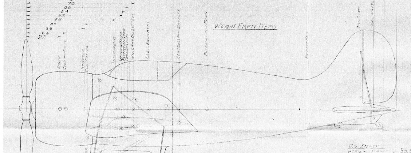
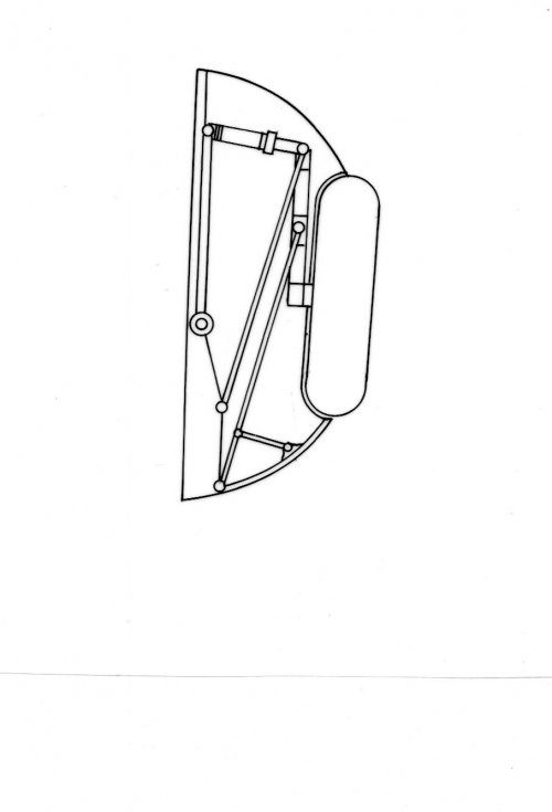
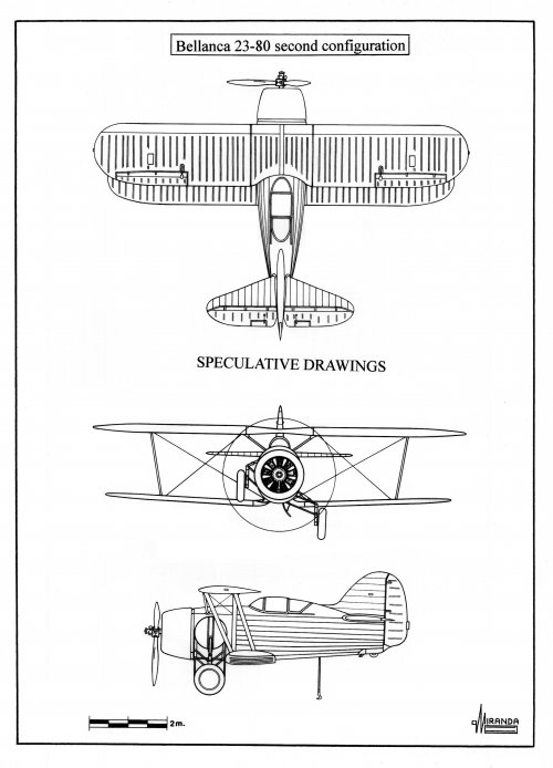
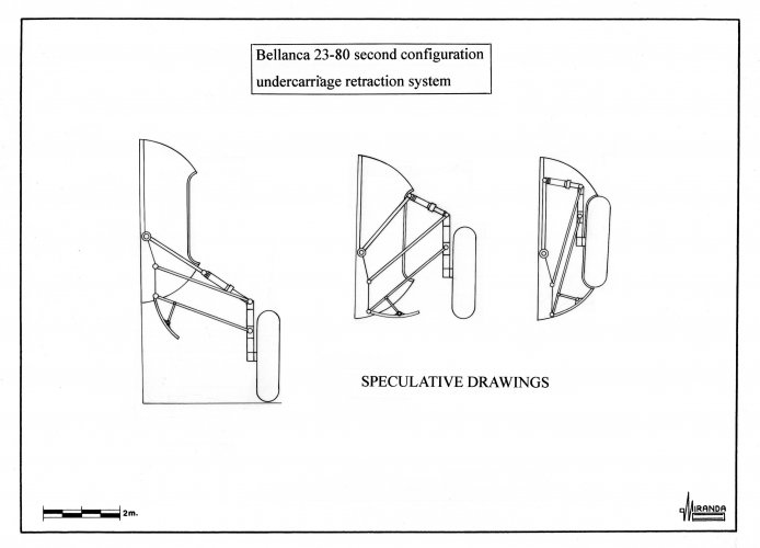
Bellanca proposed the biplane Model 22-80 with Dayton-Wright manually operated retractable undercarriage and the high-wing monoplane Model 23-80, Vought proposed the V-139 project, a monoplane with fixed undercarriage, but the Navy was only interested in fast planes.
In early June 1936 the Curtiss H-75B monoplane was tested by naval pilots at Anacostia NAS.
The prototype demonstrated excellent ability to take off in just 53 meters with a headwind of 25 knots (46 km/h), but its landing speed and forward visibility were deemed inadequate for operating from aircraft carriers.
After the entry into service of the Seversky P-35 in May 1937, most Army pilots believed that they could operate their fighters from a carrier if the need arose.
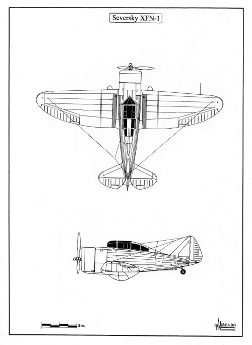
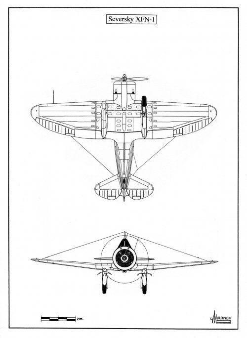
The manufacturer decided to build a navalized version of the P-35 to participate in the U.S. Navy shipboard single-seat competition. The prototype was powered by a Wright R-1820-22 and had a new vertical windshield specially designed to improve forward visibility during landing, a fully enclosed undercarriage and one arresting hook.
The new aircraft (NX 1254) was given the U.S. Navy designation XNF-1 (Experimental Naval Fighter No.1) and tested at Anacostia NAS in September 1937.
Qualification trials revealed that the prototype had too high landing speed for safe carrier operations. As a result, the type was cancelled in favor of the Brewster XF2A-1.
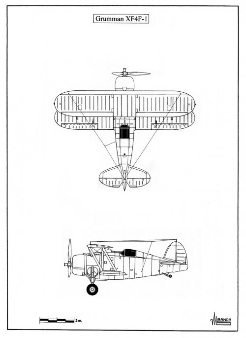
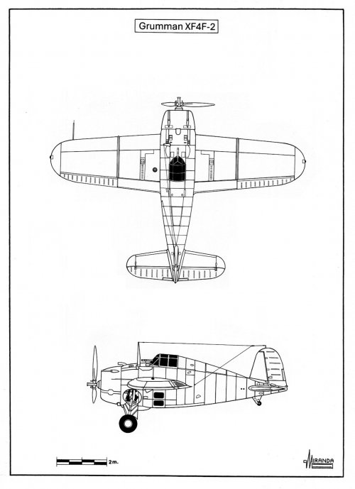
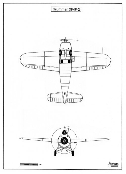
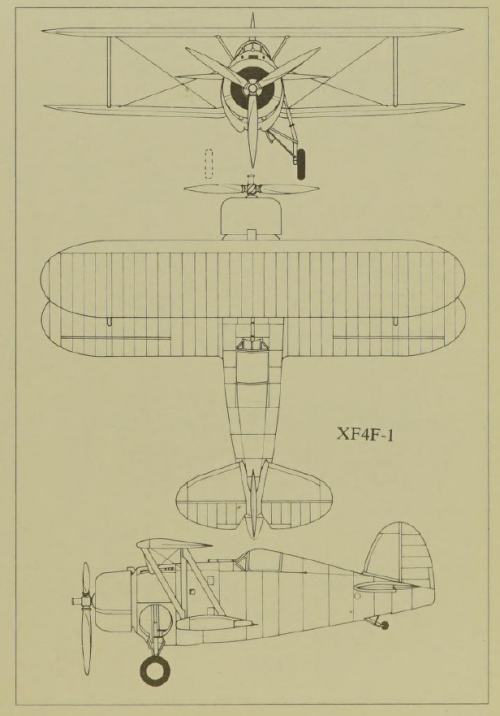
After participating in the competition for two monoplane designs, Grumman realized that a biplane would never win a contract, the Bu Aer XF4F-1 was cancelled and the design team set to work on the new mid-win cantilever monoplane Model G-18 equipped with manually retractable landing gear.
On July 28, 1936, the Navy issued a contract for a prototype under the designation XF4F-2 (Bu Aer 0383) powered by one P&W R-1830-66 supercharged.
The prototype was tested at Anacostia NAS between December 1937 and April 1938 when engine failure caused a crash landing. Following repairs, evaluation continued until August.
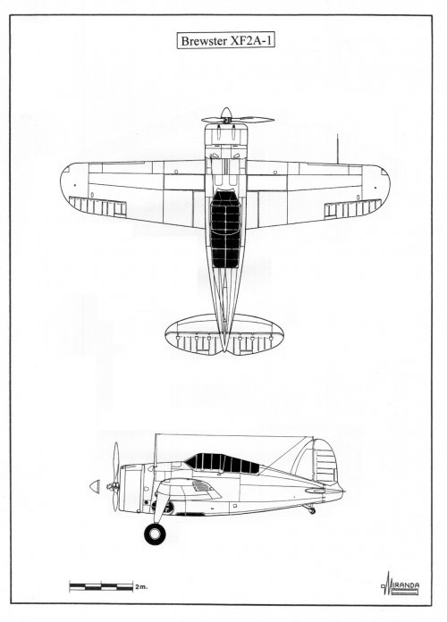
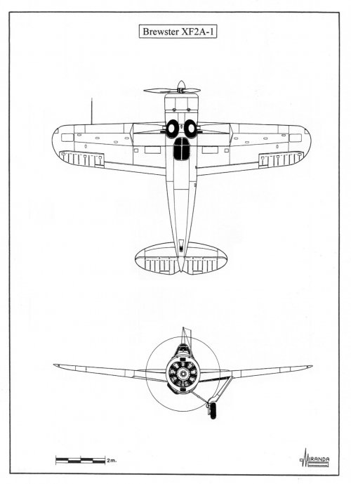
During the evaluation period, the Grumman reached 467 km/h, the Brewster 451 km/h and the Seversky 402 km/h, but the Brewster outperformed the others in maneuverability.
When the Grumman prototype was damaged after a crash, Brewster was awarded a production contract for 54 F2A-1 fighters in October 1938.
Grumman XF4F-1 technical data
Wingspan: 8.23 m, length: 7.13 m, height: 3.53 m, wing area: 20 sq. m, max weight: 2,038 kg, power plant: one P&W R-1535-94, 14 cyl. two rows, air cooled radial engine rated at 825 hp.
Grumman XF4F-2 technical data
Wingspan: 10.37 m, length: 8.05 m, height: 3.48 m, wing area: 21.56 sq. m, max weight: 2,511 kg, max speed: 463 km/h, power plant: one P&W R-1830-66, 14 cyl. two rows, air cooled radial engine rated at 1,050 hp.
Seversky XFN-1 technical data
Wingspan: 10.97 m, length: 7.44 m, height: 2.77 m, wing area: 20.44 sq. m, max weight: 2,373 kg, max speed: 402 km/h, power plant: one Wright R-1820-22, nine cylinders, air cooled radial engine rated at 950 hp.
Brewster XF2A-1 technical data
Wingspan: 10.67 m, length: 7.73 m, height: 3.56 m, wing area: 19.41 sq. m, max weight: 2,220 kg, max speed: 451 km/h, power plant: one Wright R-1820-22, nine cylinders, air cooled radial engine rated at 950 hp.
The British began using flaps on the Fairey Flycatcher to reduce take-off and landing distances as much as possible, they also introduced the use of V-12 engines in the Hawker Nimrod and stainless-steel structures in the Hawker Osprey, but when it came time to use monoplane fighters, the Fleet Air Arm ran into the problem that the carriers of the Illustrious Class had been designed with elevators that were too small to accommodate only aircraft with folding wings.
When the Second World War began, it was necessary to hastily navalized 98 Gloster Gladiator Mk. II biplanes, which had been built for the RAF, until folding wing Fairey Fulmars became available in July 1940.
Nor had American naval fighters evolved much since the Boeing F4B entered service in 1933, the introduction of a supercharger in the F4B-3 version did not improve its acceptance aboard the U.S.S. Saratoga and the model was eventually transferred to the U.S. Marines.
The Curtiss F11C/BTC-2, fitted with semi-enclosed cockpit canopy, was also not very successful, and was used as a fighter-bomber in the U.S.S. Saratoga and the U.S.S. Enterprise between 1933 and 1938.
In 1934 operational tests began on the BF2C-1 version, equipped with Dayton-Wright retractable landing gear, but this innovation created many problems along with the timber and metal mixed structure wing construction system, the model was only in service for a few months.
At that time, the use of retractable landing gear in naval aircraft was not due to the need to increase speed, because they were all biplanes, but to the problem of quickly sinking in an inverted position when an aircraft with a fixed gear tried to splash down in an emergency, making it difficult for the pilot to evacuate.
In 1933 the Grumman FF-1 entered service equipped with a new type of retractable gear, developed by Loening, which was safer than that used by the Curtiss BF2C-1, and with a new hydrodynamic belly designed to facilitate aquaplaning maneuver.
This innovation was a success, and the U.S. Navy ordered two new biplane fighters with enclosed cockpit hoods based on the FF-1 formula, the Grumman F2F-1 (1935-1940) and the Grumman F3F-1 (1936-1940).
But in 1937 the rules of the game changed drastically with the entry into service of the Mitsubishi A5M, a Japanese low-wing monoplane that saw combat in China.
The A5M surpassed everything the Chinese threw at it:
-Biplanes with fixed landing gear Curtiss Hawk II, Gloster Gladiator Mk. I, Polikarpov I-152 and Fiat CR.32.
-Biplanes with retractable landing gear Curtiss Hawk III and Polikarpov I-153.
-Monoplanes with low wings braced and fixed landing gear Boeing Model 281 and Breda 27.
-Monoplanes with cantilever wings and fixed landing gear Dewoitine D.510 and Curtiss Hawk 75 M.
When intelligence services began reporting the successes of the A5M, Western designers did not believe that it was possible to build a fighter with such performance and maneuverability using the technology of the time because until then Japanese designers had limited themselves to copying Western designs such as the Boeing Model 100 and the Hawker Nimrod.
The reality was that the A5M had originally been designed as a land-based naval fighter for the war in China, but the extraordinary lightness of its aluminum construction and the use of powerful engines allowed it to take off and land from the Hosho Class aircraft carriers.
Since 1932, French designers had been experimenting with high-wing monoplanes for the aircraft carrier Béarn. The Wibault 74 naval fighter entered service in 1932 and was replaced by the flap-equipped Dewoitine D. 373 in 1934.
The high-wing fighters had exceptional STOL qualities and were ideal for use on aircraft carriers, but their maneuverability was poor, and they could not compete with low-wing monoplanes.
During the second half of the 1930s, the rise of aggressive dictatorships produced new designs of fast monoplane bombers that posed a very real threat to Allied aircraft carriers.
In 1936 a Heinkel He 111 airliner made a demonstration flying at 402 km/h, in 1938 the He 111 E-1 combat version reached 420 km/h with bomb loading and was impossible for the Spanish Polikarpov I-16 to intercept.
In August 1937, the Japanese land-based naval bomber Mitsubishi G3M entered service with 4,400 km range, 9,200 m service ceiling and 375 km/h top speed.
A year later, Chinese fighters Curtiss Hawk III and Boeing 281 discovered that they could not intercept the new Imperial Japanese Army Mitsubishi Ki.21 bomber with 10,000 m ceiling and 485 km/h top speed.
In September 1939 the Junkers Ju 88 A-0 heavy dive bomber, with 450 km/h and 8,000 m ceiling, entered service.
To make the situation even worse, Germany and Japan began developing carrier-based dive bombers.
In September 1939 the Junkers Ju 87C, the navalized version of the Stuka with 382 km/h and 7,000 m ceiling, entered service, in November it was followed by the Aichi D3A with 450 km/h and 8,000 m.
Fortunately for the Americans, the Essex Class aircraft carriers had no size problems in the elevators (18 x 20 m) and could operate with monoplanes.
The design of naval fighters with retractable landing gear was no longer oriented towards aquaplaning but towards reducing drag to increase speed.
At the end of 1935, the U.S. Navy Bureau of Aeronautics issued a specification calling for a 300-m.p.h. carrier-based single-seat fighter as replacement of the obsolete biplane F3F.
The Grumman Company proposal was the Model G-16 which was a F3F extensively modified with Loening manually operated retractable landing gear.
To improve performance, the designers decided to use a P&W R-1535-94 engine with a smaller diameter of 207-mm than the Wright R-1820-22 used in the F3F, they also reduced the wingspan by 1,520-mm and the maximum weight by 203 kg.
To compensate for the decrease in wing surface, it was decided to install large flaps on the upper wing.
Several designs were also submitted by Bellanca, Brewster, Curtiss, Seversky and Vought.
Bellanca proposed the biplane Model 22-80 with Dayton-Wright manually operated retractable undercarriage and the high-wing monoplane Model 23-80, Vought proposed the V-139 project, a monoplane with fixed undercarriage, but the Navy was only interested in fast planes.
In early June 1936 the Curtiss H-75B monoplane was tested by naval pilots at Anacostia NAS.
The prototype demonstrated excellent ability to take off in just 53 meters with a headwind of 25 knots (46 km/h), but its landing speed and forward visibility were deemed inadequate for operating from aircraft carriers.
After the entry into service of the Seversky P-35 in May 1937, most Army pilots believed that they could operate their fighters from a carrier if the need arose.
The manufacturer decided to build a navalized version of the P-35 to participate in the U.S. Navy shipboard single-seat competition. The prototype was powered by a Wright R-1820-22 and had a new vertical windshield specially designed to improve forward visibility during landing, a fully enclosed undercarriage and one arresting hook.
The new aircraft (NX 1254) was given the U.S. Navy designation XNF-1 (Experimental Naval Fighter No.1) and tested at Anacostia NAS in September 1937.
Qualification trials revealed that the prototype had too high landing speed for safe carrier operations. As a result, the type was cancelled in favor of the Brewster XF2A-1.
After participating in the competition for two monoplane designs, Grumman realized that a biplane would never win a contract, the Bu Aer XF4F-1 was cancelled and the design team set to work on the new mid-win cantilever monoplane Model G-18 equipped with manually retractable landing gear.
On July 28, 1936, the Navy issued a contract for a prototype under the designation XF4F-2 (Bu Aer 0383) powered by one P&W R-1830-66 supercharged.
The prototype was tested at Anacostia NAS between December 1937 and April 1938 when engine failure caused a crash landing. Following repairs, evaluation continued until August.
During the evaluation period, the Grumman reached 467 km/h, the Brewster 451 km/h and the Seversky 402 km/h, but the Brewster outperformed the others in maneuverability.
When the Grumman prototype was damaged after a crash, Brewster was awarded a production contract for 54 F2A-1 fighters in October 1938.
Grumman XF4F-1 technical data
Wingspan: 8.23 m, length: 7.13 m, height: 3.53 m, wing area: 20 sq. m, max weight: 2,038 kg, power plant: one P&W R-1535-94, 14 cyl. two rows, air cooled radial engine rated at 825 hp.
Grumman XF4F-2 technical data
Wingspan: 10.37 m, length: 8.05 m, height: 3.48 m, wing area: 21.56 sq. m, max weight: 2,511 kg, max speed: 463 km/h, power plant: one P&W R-1830-66, 14 cyl. two rows, air cooled radial engine rated at 1,050 hp.
Seversky XFN-1 technical data
Wingspan: 10.97 m, length: 7.44 m, height: 2.77 m, wing area: 20.44 sq. m, max weight: 2,373 kg, max speed: 402 km/h, power plant: one Wright R-1820-22, nine cylinders, air cooled radial engine rated at 950 hp.
Brewster XF2A-1 technical data
Wingspan: 10.67 m, length: 7.73 m, height: 3.56 m, wing area: 19.41 sq. m, max weight: 2,220 kg, max speed: 451 km/h, power plant: one Wright R-1820-22, nine cylinders, air cooled radial engine rated at 950 hp.


")