Aircraft geometry & Mach cone - math and myths

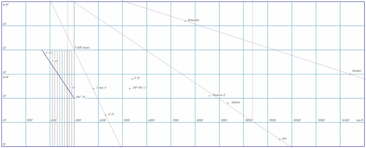
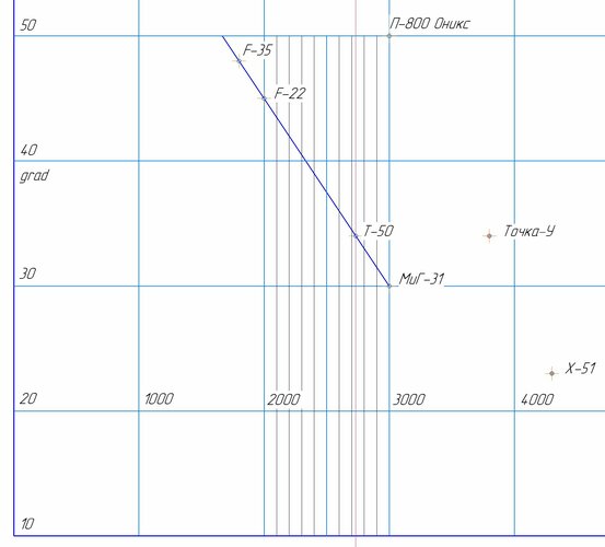
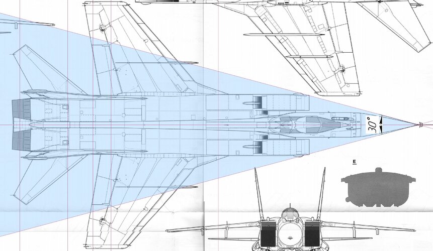
In aircraft, the sweep of the leading edge of the wing is directly related to the estimated flight speed. There are exceptions to the rules, but there are not many of them
F-22 - 42 grad
Su-57 - 48 grad

(48 : 42) * 1593 km/h = 1820 km/h

Very seldom is that truly the case. The F-15 for example can hit Mach 2.5 but has a sweep angle designed for Mach 0.8 agility.

The Mach angle of the Su-57 planform suggests that it hits its limit around 2.2
 
The Mach angle of the Su-57 planform suggests that it hits its limit around 2.2
The angle of the leading edge of the air intake corresponds to M = 2.35 - 2.5
The angle of the radiotransparent cone corresponds to a velocity of M >2.7
 

Attachments

  • cone angle.JPG
    cone angle.JPG
    151.9 KB · Views: 119
Last edited:
The angle of the leading edge of the air intake corresponds to M = 2.35 - 2.5
The angle of the radiotransparent cone corresponds to a velocity of M >2.7

I think the nosecone is shaped like that for AoA vortex / airflow reasons, not Mach shaping. Mach 2.7 would put the shockwave right into the centre of the wing leading edge, which would destroy lift ( and probably the structure ).

Even Mach 2.35 would impinge the wing tips, though interestingly right at the outer limit of the slats.
 

Attachments

  • Su-57_M2.35_cone.png
    Su-57_M2.35_cone.png
    54.2 KB · Views: 116
Last edited:
By the way, the wingtips have a slightly smaller sweep... ;)
 

Attachments

  • wing_su-57.JPG
    wing_su-57.JPG
    186.7 KB · Views: 136
  • mig-31.JPG
    mig-31.JPG
    462.6 KB · Views: 157
The angle of the leading edge of the air intake corresponds to M = 2.35 - 2.5
The angle of the radiotransparent cone corresponds to a velocity of M >2.7
By the way, the wingtips have a slightly smaller sweep... ;)

That's a fundamentally incorrect way of calculating the Mach cone angle. At its simplest, Mach angle is calculated as mu = asin(1/M), where mu is the angle from the freestream, so cone angle would be double that.

For oblique shocks that turns the flow, you have the more complex theta-beta-M equation for oblique shocks which is represented by this table for various Mach numbers. Note that this is 2D ramp flow only.
 

Attachments

  • oblique-chart.png
    oblique-chart.png
    942.6 KB · Views: 96
How do we apply this knowledge to real aircraft?
From my loose memory of university aerodynamics, the air encounters different oblique shocks as it passes around a body - weak and strong. A normal shock decelerates the air to subsonic, and oblique shock transitions it to a different mach number and in doing so causes pressure changes. The smaller the shock, the lower the wave drag.

The above chart is showing the shock angles (y-axis) caused by the body deflection angles (x-axis) at different mach numbers. M1 - right side of graph is the incident mach number. So at Mach 3.2, a 20deg deflection causes a weak oblique shock angle of 36deg or a strong shock angle of 82deg. Which you get depends on the pressure differences fore to aft. After a strong shock the airspeed is subsonic, after the weak shock it is still supersonic, unless M1 was only just above sonic. The bottom line running left to right corresponds to the shock angles at which M2 becomes subsonic, and the top line running left to right above that, indicates the maximum shock angle before it's a strong shock.

This is the about the best explanatory images I could pull from the internet:

1710273326159.png
1710272116327.png
1710272239006.png
 
Last edited:
If looks to me like many modern supersonic jets: CF-18, CF-104, etc. rely on the tip of the nose radome to define the shock cone and the rest of the airframe just follows inside that shock cone.
 
I was trying to find an obvious addiction, especially since it really exists.another thing is that at hypersonic speeds, the shape of the nose can be almost any
 
How do we apply this knowledge to real aircraft?
Generally?

Take a plan view of the aircraft. Draw a straight line from tip of the nose/radome to the wingtips. Measure included angle, that's 2*mu.

Take equation of mu = asin(1/Mach number) and solve for mach number.

That's the likely Vne of the airframe.

Example: SR71s are said to max out at Mach 3.55, where the nose shock would hit the ailerons at the wingtips.
 
The layout density of the empty steel MiG-31 is 292 kg/m3, the layout density of the duralumin Su-27 is 250 kg/m3, the MiG-29 is 250 kg/m3. This is a fee for overcoming the "thermal barrier" in the area of 2700 km/h. But that's probably not the point, but the fact that getting the ends of the wing into the "Mach cone" is not critical
 
Does/Can an asymmetric cone generate lift?
Anything can fly with enough speed, I like to think of lifting bodies as a heavily refined asymmetric cone, So using that approach I suppose so. The X-24C is pretty cone like.
 
Does/Can an asymmetric cone generate lift?
The existence of "waveriders" suggests that to be true. IIRC the concept, a waverider basically has the belly not quite in contact with a shock wave or cone to create lift (and also limit airframe heating by keeping the shockwave and supersonic airflow off the airframe).

 
Using Mu = arcsin (1/mach) and MiG-25 drawing I get this - red is M = 2.83, green = 2.35. I've drawn for nose and intake shocks.

Mach 2.35 - 25.18 deg from centreline
Mach 2.83 - 20.69 deg from centerline


MiG-25 Mach angle.png So the wings are inside the nose mach cone at max 'cruise speed' of M=2.35 Its only if you dash faster than M=2.35 that the shock hits the wing.

Note that the MiG-25 had to have anti-flutter weights added to the wingtips.
 
Who knows what speed this thing would have reached if it had been able to take off.?
 

Attachments

  • 96d0fbcc-2566-429d-bace-86bfc6cae8ea.jpg
    96d0fbcc-2566-429d-bace-86bfc6cae8ea.jpg
    87.4 KB · Views: 16
  • yak-1000-image01.jpg
    yak-1000-image01.jpg
    71.6 KB · Views: 16
Anything can fly with enough speed, I like to think of lifting bodies as a heavily refined asymmetric cone, So using that approach I suppose so. The X-24C is pretty cone like.
Slight correction - anything can fly with enough *propulsive power*.
 
If an X-3 could, why couldn't that?
Development was canceled before Yakovlev had sorted out the combination of undercarriage instability and ineffective ailerons, causing the Yak-1000 to be blown off the runway during a high-speed taxi test. It never flew.
 

Similar threads

Back
Top Bottom