Some questions about the Heinkel He 219's Nacelle Thrust Line

richdlc

ACCESS: Restricted
Joined
18 June 2020
Messages
32
Reaction score
20
Hi guys - I am new here, this group was recommended to me by some guys over on Facebook.
My name's Richard Carrick, I am the MD of Chandos Publications - here's my website, not to self-promote but to show you I am a real person and not some kind of troll!

www.chandospublications.co.uk

anyway, we publish high-end books on the Luftwaffe. Our third book will be on the He 219.

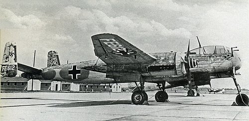
We have commissioned three authors to work on the book - Kjetil Aakra, Marcel Hogenhuis and Martin Streetly. However, I am doing a little research of my own. I am also a model maker and one of the biggest bugbears with the available kits seems to be the accuracy (or otherwise) of the engine nacelles. When looking at numerous photos of production model He 219s, many people have pointed out that the Thrust Line of the engines and cowlings points ever so slightly downward (see attached image - note the exhausts which are perpendicular to the engine thrust line.)

Now it's my contention that this phenomenon is something to do with the addition of extra fuel tanks in the production variants, but I was wondering if anyone had for example William Wolf's 'B-26 Marauder The Ultimate Look' - as far as I understand it, a direct comparison between the B-26C and B-26G should show a change in the engine nacelle shape and the incidence to the wing. I want to demonstrate that changes in later models of the He 219 also resulted in a noticeably similar visible difference between production and prototype models.

If the pertinent information is in Wolf's book then I (or rather our authors) can then say that this phenomenon could be found on many aircraft of this period, not just the He 219.

I'm sure it's not just the B-26G that we can compare here. Are there other aircraft of the period that show noticeable changes in the shape/thrust line of engines? The wing root of the He 219 that is disassembled at the Udvar Hazy Center is definitely aligned with the airframe's longitudinal axis, but (again referring to the attached image) the engine gondolas are definitely tilted at a slight angle.

I'm hoping we can have an interesting debate about this phenomenon!

Rich Screen Shot 2020-06-18 at 13.51.08.png
 
Last edited:
If you want to prove the thrust line changed between prototype and production, drawings and photos are the way to go. It's hard to judge from one photo!

Not sure that analogy to other designs is relevant here. It is however definitely the case that other contemporary designs had similar alterations. The P-38 changed engine model and thrust lines from the XP-38 for example. Altered thrust lines for piston engines could be a sign of compensation for balance/stability issues. Equally, the angle of attack in high speed flight and the angle at which the plane sits on it's undercarriage on the ground are very different things. Perhaps at high speed, the angle of the thrust line is perfectly aligned to the airflow and the nose is a little high, which wasn't catered for on the prototype.
 
Last edited:
Note that jets often have offset thrust lines for a variety of reasons, with much greater effect then piston engine thrust lines. Ultimately the only way to be *sure* of the reason for the change is documentation - anything else is simply more-or-less-informed speculation.
 
[...] Perhaps at high speed, the angle of the thrust line is perfectly aligned to the airflow and the nose is a little high, which wasn't catered for on the prototype.
Sometime the most important parameter is cruise and the thrust line would be the one that maximize the pull (/push) effect with the higher Cl/CD position for the wing.

If engines are swap with a radical effect on power, thrust line would have to be corrected as well as the angle b/w the chord line at cruise and the thrust line to reflect the variation in mass and/or CG (different wing pitch).

Regarding max speed, a greater impact on drag is drag related to lift. Many planes of that era fly with their noze slightly down (109, B-52 at low alt...).

Last but but not least, don't forget wing twist along the span (washout) that might alter the perception of the position of the engine if seen with different wing section as reference.

My 2 cents.
 
Re. Overscan "Ultimately the only way to be *sure* of the reason for the change is documentation - anything else is simply more-or-less-informed
speculation." AMEN! From experience, trying to measure accurately design parameters such as AOI (angle of incidence), airfoil chord, thrust
lines relative to longitudinal reference,etc. using photographs or even direct reference to actual airframes is pretty much a waste of time. I was
given total access to a Ju 88 to photograph, measure, etc, and I am an engineer who has experience with field measurement of equipmeent.
The problemis that aircraft are very complex shapes and the parameters have precise definitions that do not necessarily relate to identifiable
points on an airframe. You need drawings from the source, in this case, Heinkel. Even the drawings in German aircraft tech manuals are no
guarantee of accuraccy.
Next, once you have accurate dimensional and arrangement information, unless you have documentation of the original design process, ,i.e.
design studies, reports, calculations, correspondence, speculation is just that and pretty worthless.
Fortunately, some of the type material needed for design analysis is available from the Wright Field captured documents available from
USA NASM, I do not know if there is much on the He 219, I do know my collection has very little hard data on that type.
Another source is Eddie Creek, in addition to his photo collection, he had a lot of previously unseen tech stuff in my subject area.
Soo, if you want to be "high end" it is not just about pretty profiles, drawings and photos.
Finally, no matter how hard you try, there will be errors and omissions.
Best regards,
Artie Bob
 
Rich, this is a magnificent quest. Looking quickly at a handful of photos, I cannot say for certain that the thrust line of the engines of the He 219 is distinctly not in line with the fuselage reference lines (water lines). The wing obviously has several degrees of incidence (likely twist for washout, too) that distracts from seeing how the nacelles are rigged. It also doesn't help that the plane sits with such a pronounced nose-up attitude on its revolutionary tricycle landing gear. The answer is out there. After all, the US Air and Space Museum has a recently restored He 219 airframe, and I'd bet their restoration researchers have amassed a thick file of historical German documents.

Good luck!

(Attached is the open-domain black and white photo of the captured He 219 with the Project Lusty designation "FE612" that shows the complications of the geometry, as well as a non-official line drawing.)
 

Attachments

  • He 219 rt side FE612.jpg
    He 219 rt side FE612.jpg
    524.9 KB · Views: 124
  • He 219 side view line dwg.pdf
    97.5 KB · Views: 64
[...] Perhaps at high speed, the angle of the thrust line is perfectly aligned to the airflow and the nose is a little high, which wasn't catered for on the prototype.
Sometime the most important parameter is cruise and the thrust line would be the one that maximize the pull (/push) effect with the higher Cl/CD position for the wing.

If engines are swap with a radical effect on power, thrust line would have to be corrected as well as the angle b/w the chord line at cruise and the thrust line to reflect the variation in mass and/or CG (different wing pitch).

Regarding max speed, a greater impact on drag is drag related to lift. Many planes of that era fly with their noze slightly down (109, B-52 at low alt...).

Last but but not least, don't forget wing twist along the span (washout) that might alter the perception of the position of the engine if seen with different wing section as reference.

My 2 cents.

I would agree particularly with the last point;- aeroelastic’s (the amount of flight induced wing flexing, especially twist) is notoriously difficult to predict before first flight even for today’s big players, using the latest analysis tech. So quietly, almost unnoticed to most observers, it’s routine to fine tuning the wing twist based on real flight loaded observations because it makes a big difference to the cruise fuel burn..... of course a few sub optimal examples might have been built before that’s done;- note the early production airframes of the latest airliner going to scrapyards (787 the ‘terrible teens’) or museum’s.

If it looks right on the ground it’s probably wrong in flight.
 
Last edited:
Zoukei-Mura built their He-219 kit off their examination of the NASM plane. It might be worthwhile contacting them and see if they would share their documentation since they went through the process of very precise measurement of the aircraft to develop their model kit. Information on the development of their He-219 kit can be found on this page at the series of links 038 through 041 on this page: https://www.zoukeimura.co.jp/en/products/sws06_He219Uhu.html
 

Attachments

  • Zoukei Mura Uhu Edition Links.JPG
    Zoukei Mura Uhu Edition Links.JPG
    205.7 KB · Views: 111
  • ZM He-219 2.JPG
    ZM He-219 2.JPG
    83.9 KB · Views: 117
  • ZM He-219.JPG
    ZM He-219.JPG
    112.8 KB · Views: 115
Note that jets often have offset thrust lines for a variety of reasons, with much greater effect then piston engine thrust lines. Ultimately the only way to be *sure* of the reason for the change is documentation - anything else is simply more-or-less-informed speculation.

thanks, noted!

[...] Perhaps at high speed, the angle of the thrust line is perfectly aligned to the airflow and the nose is a little high, which wasn't catered for on the prototype.
Sometime the most important parameter is cruise and the thrust line would be the one that maximize the pull (/push) effect with the higher Cl/CD position for the wing.

If engines are swap with a radical effect on power, thrust line would have to be corrected as well as the angle b/w the chord line at cruise and the thrust line to reflect the variation in mass and/or CG (different wing pitch).

Regarding max speed, a greater impact on drag is drag related to lift. Many planes of that era fly with their noze slightly down (109, B-52 at low alt...).

Last but but not least, don't forget wing twist along the span (washout) that might alter the perception of the position of the engine if seen with different wing section as reference.

My 2 cents.

Interesting points... regarding more powerful engines, ironically this wasn't the case with the He 219. Eric 'Winkle' Brown wasn't particularly enamoured of the (captured, British evaluated) aircraft, saying it was underpowered. (Wings of the Luftwaffe - Brown)

The He 219 was also designed for the Jumo 222 in the 2000-2500 hp performance class, with which it had achieved excellent flight performance. Due to the development deficits in the Jumo 222 caused by the RLM, the He 219, similar to the Ju 388, had to be equipped with engines that were too weak. (Junkers Ju 388: Development, Testing and Production of the Last Junkers High-Altitude Aircraft - Christoph Vernaleken)

As for the washout, I read somewhere that this occurs outboard of the engine gondolas.


Re. Overscan "Ultimately the only way to be *sure* of the reason for the change is documentation - anything else is simply more-or-less-informed
speculation." AMEN! From experience, trying to measure accurately design parameters such as AOI (angle of incidence), airfoil chord, thrust
lines relative to longitudinal reference,etc. using photographs or even direct reference to actual airframes is pretty much a waste of time. I was
given total access to a Ju 88 to photograph, measure, etc, and I am an engineer who has experience with field measurement of equipmeent.
The problemis that aircraft are very complex shapes and the parameters have precise definitions that do not necessarily relate to identifiable
points on an airframe. You need drawings from the source, in this case, Heinkel. Even the drawings in German aircraft tech manuals are no
guarantee of accuraccy.
Next, once you have accurate dimensional and arrangement information, unless you have documentation of the original design process, ,i.e.
design studies, reports, calculations, correspondence, speculation is just that and pretty worthless.
Fortunately, some of the type material needed for design analysis is available from the Wright Field captured documents available from
USA NASM, I do not know if there is much on the He 219, I do know my collection has very little hard data on that type.
Another source is Eddie Creek, in addition to his photo collection, he had a lot of previously unseen tech stuff in my subject area.
Soo, if you want to be "high end" it is not just about pretty profiles, drawings and photos.
Finally, no matter how hard you try, there will be errors and omissions.
Best regards,
Artie Bob

Thanks! I guess I can try and contact the NASM. I've already made tentative contact with the Udvar Hazy Center, and I did actually have intentions to fly out there. I think that ambition is now buggered up due to bloody covid though.

Eddie Creek is already part of our team - he's supplying the photos and other docs;)

Rich, this is a magnificent quest. Looking quickly at a handful of photos, I cannot say for certain that the thrust line of the engines of the He 219 is distinctly not in line with the fuselage reference lines (water lines). The wing obviously has several degrees of incidence (likely twist for washout, too) that distracts from seeing how the nacelles are rigged. It also doesn't help that the plane sits with such a pronounced nose-up attitude on its revolutionary tricycle landing gear. The answer is out there. After all, the US Air and Space Museum has a recently restored He 219 airframe, and I'd bet their restoration researchers have amassed a thick file of historical German documents.

Good luck!

(Attached is the open-domain black and white photo of the captured He 219 with the Project Lusty designation "FE612" that shows the complications of the geometry, as well as a non-official line drawing.)

many thanks! As mentioned earlier, washout occurs outboard of the engine gondolas. I've no idea how this would affect my / our / your perception of the angle of incidence of the engines.

You are also right about the landing gear and the nose high attitude of the forward section, it plays havoc with what you are looking at.

[...] Perhaps at high speed, the angle of the thrust line is perfectly aligned to the airflow and the nose is a little high, which wasn't catered for on the prototype.
Sometime the most important parameter is cruise and the thrust line would be the one that maximize the pull (/push) effect with the higher Cl/CD position for the wing.

If engines are swap with a radical effect on power, thrust line would have to be corrected as well as the angle b/w the chord line at cruise and the thrust line to reflect the variation in mass and/or CG (different wing pitch).

Regarding max speed, a greater impact on drag is drag related to lift. Many planes of that era fly with their noze slightly down (109, B-52 at low alt...).

Last but but not least, don't forget wing twist along the span (washout) that might alter the perception of the position of the engine if seen with different wing section as reference.

My 2 cents.

I would agree particularly with the last point;- aeroelastic’s (the amount of flight induced wing flexing, especially twist) is notoriously difficult to predict before first flight even for today’s big players, using the latest analysis tech. So quietly, almost unnoticed to most observers, it’s routine to fine tuning the wing twist based on real flight loaded observations because it makes a big difference to the cruise fuel burn..... of course a few sub optimal examples might have been built before that’s done;- note the early production airframes of the latest airliner going to scrapyards (787 the ‘terrible teens’) or museum’s.

If it looks right on the ground it’s probably wrong in flight.

thank you, worth bearing in mind. AFAIK all the production He 219's had the same engines. Not sure about changes to the wing shape throughout its service life though. Less than 300 airframes were built. Will have to look into this further!

Zoukei-Mura built their He-219 kit off their examination of the NASM plane. It might be worthwhile contacting them and see if they would share their documentation since they went through the process of very precise measurement of the aircraft to develop their model kit. Information on the development of their He-219 kit can be found on this page at the series of links 038 through 041 on this page: https://www.zoukeimura.co.jp/en/products/sws06_He219Uhu.html

Well funnily enough I am quite friendly with Kuniyoshi, the big boss man's son. I got talking to him at the IPMS Nationals a few years ago, and ZM have agreed to let us use their scale drawings in the book (albeit amended by us). I will certainly enquire further as to their measurements, but don't forget (and this is frequently mentioned on modelling forums) that they took all of their measurements with the wings off the fuselage.
 
Last edited:
Aeroelastic wing structural twist is different to washout;- it’s sometimes called wing jig shape. The whole wing is deliberately built In the jig with a twist such that the flight loads will correct back to the design intent flight orientation. The washout is part of the design intent orientation so its jig shape is likewise deflected back to the desired figures . Also I’m aware of the final optimal flight wing taking several iterations after the first prototype, with normally the first iteration being applied to the next wing in build fairly shortly after first flight. In my experience the wing jigs are made so that a twist adjustment is readily accommodated as the production run progress's.
It means the wing jig shape will be different to the 1g on ground shape which will be different to the flight shape.

Holy cow! Thanks for the answer...

Have you read this?


No idea how good it is, but as a critique of previously published books on the He 219, it would be worth a try.

well, Ron Ferguson was originally writing the book for us, before he broke contract and disappeared ( much more to it than I am willing to go into here.) Our authors are aware of the book, not sure if the answer to this question is in it but I can find out
 
On the subjects of wash-out and aero-elasticity ....
Wash-out is most commonly used to tailor wing stall characteristics. It involves setting the wing-tip angle of incidence slightly shallower (nose down) to delay tip stall until after the wing-root is fully stalled. The goal is to maintain aileron (roll) control when the wing is partially stalled.
Other ways - to delay tip stall - include changing the airfoil from root to tip, stall fences, etc. The most recent NASA research (1970s) produced the extended leading edge cuffs as seen on the Cirrus and Kodiak.
 
Yes, Riggerrob, but it also serves to decrease the induced drag of the wing, by making the lift vector practically zero at the tip.
Aero-elasticity is a complex phenomenom, that is inherent to the construction characteristics of the wing and the material used. It normally makes forward swept wing very difficult to maintain elastic stability. That's why you see so little forward swept winged aircraft, despite the aerodynamical advantages.
 
This is probably obvious to all, but I'll point it out anyway, just in case: useful as they are, photographs introduce their own distortions, as anyone who has photographed a tall building with a normal lens has found. The focal length of the lens, the relative distances between parts of the image, depth of field, how the photographer holds the camera, and even the degree to which the camera keeps the film flat and perpendicular to the axis of the lens can alter the "real" shape of the object. The eye also introduces corrections/distortions of its own, which complicates the issue still more. So, while I am hardly enough of an expert on optics to say anything definitive on such things, I'd join the others in advising caution when drawing conclusions from photos alone. The photo that you attached appears to have been taken from fairly close in and from slightly to one side (note the distortion in the Balkenkreuz). The nose and tail are well off axis and in a different plane relative to engine nacelles and the wing tip, which is closer to the lens than any of the other parts. So it is at least possible that the apparent, relative alignments in the image are not conclusive.

That said, the problem of accuracy extends beyond photography. Accuracy is always relative to the conditions under which observations are made, whether in photography or in historical research. There is no one, reliable source of truth. There are only reasonable judgments.

For instance, while the colors in period color photos do depend in part on color specifications (FS, RLM, etc.), they also depend on variations in paint manufacture, storage, age/stability, and application methods, on ambient lighting, on weathering, on the time of day, atmospheric conditions, exposure, the chemistry and age of the photographic media, the mechanics of reproduction, scale effects, etc. So even the best photo cannot prove definitively what a given aircraft actually looked like at a given moment in time. This makes many of the more doctrinaire arguments that you sometimes hear at IPMS about authentic color seem a bit silly to me: I used to illustrate this with photos of a vividly blue F-104 at high altitude under a clear sky and another dull gray F-104 on the ground under a late afternoon haze.

Seen in this light, even factory drawings should be viewed with caution. Is a given drawing preliminary, corrected, final? Did manufacturing issues force major revisions that were subsequently lost or discarded, leaving the researcher with misleading, superseded sheets? Were the final drawings actually followed in all respects at every factory that built a given aircraft? Or were there locally made changes? Are the surviving drawings originals, copies, or copies of copies? On what media are they preserved? High-quality cloth, paper, or acetate sheets drawn with chemically stable, non-fading inks? Period blueprint sheets? Tracing paper? Microfilm? Photostat? Or are they later reproductions that try to reconcile conflicting, multiple originals? Are they forgeries? And so on.

The bottom line is that, as with all historical research, one obtains the best possible accuracy by making sensible use of all of one's available evidence and by understanding the provenance and history of that evidence as well as one can. Then one makes one's best judgment, presents one's case, and waits for the reviews. There never is a last word--which is a good thing for those of us who are enthusiasts, researchers, authors, reviewers, and/or publishers.
 
Aeroelastic wing structural twist is different to washout;- it’s sometimes called wing jig shape...It means the wing jig shape will be different to the 1g on ground shape which will be different to the flight shape.

I had not thought of this. It raises the additional question of what the drawing shape of a wing is in relation to the "real" shape of the wing "on the aircraft". Presumably, a factory manufacturing drawing defines the jig shape of a wing. But a general arrangement drawing from the same source might try to show the expected on-ground or in-flight shape of the same component.

So here, too, accuracy is relative both to the conditions under which an object is observed and to the purposes for which observations are made. For best results, the researcher/observer has to be aware of both factors before rendering judgment. Unarticulated, facts are meaningless. They only become information when explained.

What is real? It depends.
 
German bomber, and night fighter development, started with requirements, moved on to a wind tunnel model to actual flight testing. I have seen photos of regularly spaced wool tufts on the wings of a bomber which were filmed. Then the test pilot went through a defined number of maneuvers. The film was then analyzed to record actual air flow. I have read translated reports where the pilot listed any complaints about handling and the responsiveness of controls. As time passed, German designers were better able to solve certain problems because a knowledge base had been built up.

I have seen films of aircraft wings being put together, I don't know how fine the tolerances were but once a shape had been chosen, that was it. In the case of fighters, a few field conversion kits were created like changing machine-guns for 20 mm cannon. One presumes a factory test aircraft was flown to evaluate these.
 
thank you for all the replies. I am starting to build up a picture of what will be involved in writing some copy for our book...
I thought these might help, they are the drawings Zoukei Mura created after 3D scanning the entire airframe at Udvar Hazy (bearing in mind the wings were not attached to the airframe at the time). Note that these drawings also have the slight forward tilt of the engine gondolas. These drawings were confirmed to us by the researcher / author Ron Ferguson as the finest he'd seen, although he gave us a long list of things that needed to be done to improve them - that, however, is academic. For the purpose of this conversation I have attached the side-view only. I have added the red line myself (not sure of the technical name for it). Screen Shot 2020-06-20 at 22.53.28.png
 
The name for the red line is the centerline. Imagine the entire aircraft in 3D revolving around it. Another detail is the c/g or center of gravity. In aircraft, a weight balance needs to exist from front to back.
 
I had not thought of this. It raises the additional question of what the drawing shape of a wing is in relation to the "real" shape of the wing "on the aircraft". Presumably, a factory manufacturing drawing defines the jig shape of a wing. But a general arrangement drawing from the same source might try to show the expected on-ground or in-flight shape of the same component.

In my experience the key reference general arrangement drawing is called the “Ground Line Drawing” which depict the aircraft on its landing gear, at one g and normally max take off weight.

The wing jig shape drawing is only used by manufacturing. The principal flight shape drawings are ones derived from wind tunnel, or more recently CFD. Wind tunnel models start off as a very stiff representative of the flight, machined from ultra high tensile steel or Teak. As the development progresses, models with representative stiffness or even parametric stiffnesses can be used to investigate the likely flight shape and dynamic stability, more commonly known as flutter..... a further aeroelastic dark art.

Another thought occurred to me relating to the He 219. It’s landing gear is aft of the spar and the heavy engine is forward. So the moment couple will tend to nod the engine downwards while on the ground. With a prop there’s added complexity;- when running, the engine/prop produces gyro loads/moments, not to mention that the air coming aftwards has an upward vector on one side and downward on the other. Not easy, but if your into this kind of thinking good fun to sort it out.
 
...Note that these drawings also have the slight forward tilt of the engine gondolas....

The thrust-line of the engines looks roughly parallel to the ground line in the drawing. So, essentially, the angle of attack of the aircraft nose and wing would seem to be elevated for take off. Perhaps one of those with more knowledge of how this would determine takeoff and cruise characteristics can explain why.
 
What I know about airplane design and what affects flight comes from building and flying radio controlled model aircraft. The forces acting on RC models are the same as for full sized aircraft and their reactions are generally the same.

The reason for downward pointing nacelles: Imagine a bar balanced on a fulcrum. If you mounted a motor and prop on top of the bar over the fulcrum and ran it, the bar would still stay balanced because the thrust or pull is balanced over the fulcrum. If you moved the motor to the side of the fulcrum and added a balancing weight on the opposite side of the fulcrum so the bar stayed level and ran it, the thrust would be pulling at an offset of the fulcrum and towards the direction of the fulcrum. To bring things back into equilibrium, if you point the motor away from the fulcrum the right amount, everything will go forward in the same direction as the vertical line of the fulcrum. This is not a perfect explanation but as good as I could come up with at the moment.

Applying this to a model airplane, if the engine thrust line is very close to or parallel to a line through the center of the leading edge and trailing edge of the wing, the plane will neither climb nor dive when power is applied. If the thrust line is significantly below and parallel to the center of the leading edge and trailing edge line, the plane will climb under throttle requiring down trim to maintain level flight. When you reduce the throttle in level flight, the down trim will have to be removed or the plane will dive because of the down trim. To correct this, downthrust or pointing the thrust line down forward will allow the plane to fly level with little or no trim needed to fly level power on or off.
 
Again from model experience, the positive angle of the airplane sitting on its gear means that as the plane nears takeoff speed, the wing being at a positive angle of attack will lift the plane off if it is going fast enough without elevator input. To shorten the takeoff roll, more power can be applied with up elevator to increase the wing's angle of attack and generate sufficient lift to take off lift sooner.

The CG on a trike gear aircraft will be slightly forward of a vertical line perpendicular to the ground line and through the centerline of the main wheels. If the main wheels are too far forward, the plane can wind up sitting on its tail when there is no crew or fuel on board.
 
The name for the red line is the centerline. Imagine the entire aircraft in 3D revolving around it. .
I’ve always seen this called the “Horizontal Fuselage Datum” as it’s not parallel to the ground or engine thrust line. It’s the reference datum for fuselage manufacture and often can be considered as the fuselage drag acting point or displacement there from.
 
...Note that these drawings also have the slight forward tilt of the engine gondolas....

The thrust-line of the engines looks roughly parallel to the ground line in the drawing. So, essentially, the angle of attack of the aircraft nose and wing would seem to be elevated for take off. Perhaps one of those with more knowledge of how this would determine takeoff and cruise characteristics can explain why.

I just checked and this is the case.
 
Applying this to a model airplane, if the engine thrust line is very close to or parallel to a line through the center of the leading edge and trailing edge of the wing, the plane will neither climb nor dive when power is applied. If the thrust line is significantly below and parallel to the center of the leading edge and trailing edge line, the plane will climb under throttle requiring down trim to maintain level flight. When you reduce the throttle in level flight, the down trim will have to be removed or the plane will dive because of the down trim. To correct this, downthrust or pointing the thrust line down forward will allow the plane to fly level with little or no trim needed to fly level power on or off.
While what you say is correct I don’t think it’s a consideration with the He219. With a standard commercial twin airliner the thrust line is inherently low so the nose up pitching is corrected by a mass moment ie moving the engine well forward of the neutral pitch axis (but this always comes at a price as unlike engine thrust, mass moment is constant.... these are highly cruise optimised with powerful trim systems...moot point currently). So considering the 219 engine appears to canted downwards on the ground, if remains like this in flight (I doubt) it will produce a nose down pitch moment. With mass moment effect from engines/ammunition/guns/radar/crew also tending to pitch the nose this would seem unwise. I reckon if the design intent was to use the engine thrust to counter a mass moment it would require the engine thrust line to be rotated upward ie the opposite to what they done. To my eye the engine thrust line is so close to the drag line there was little concern about using engine thrust to balance pitch moments. Indeed on the earlier aircraft most designers tried to achieve as simple loads and moment balance as possible*;-it made the stability and control design more predictable.

* Note that on bomber aircraft, gun belt ammunition is stored close to cg and supplied to turret via tracking. This minimise moment changes as it expended.
 
Last edited:
fascinating stuff guys! thanks for this.

Perhaps it would help if I added some info about the He 219's design (this actually from a chapter in 'Junkers Ju 388: Development, Testing And Production of the Last Junkers High-Altitude Aircraft' by Vernaleken and with regards to the competition between Heinkel and Junkers and He 219 vs Ju 388):

'The He 219 was also designed for the Jumo 222 in the 2,000 to 2,500 hp performance class., which would have given an excellent performance. Restrictions imposed on the Jumo 222’s development by the RLM meant that, like the Ju 388, the type had to be equipped with less powerful engines. Heinkel turned to the DB 603....'

So given that the aircraft was designed for more powerful engines, would this have any bearing on our discussion?
 
If the engine weighed less than the Jumo 222, a downward tilt would produce something of a counteracting down force, but ballast in the nose would be an easier solution.
 
Down size of engine power - No not really.

I’ve only just noticed the comments in the original post ref the B26 - yes aeroelastic twist effects are far more pronounced in a high aspect ratio wing.
 
If the engine weighed less than the Jumo 222, a downward tilt would produce something of a counteracting down force, but ballast in the nose would be an easier solution.

the DB 603 weighed (dry weight) 920kg and the Jumo 222 1,088kg. I'm not sure of the implications for this argument
 
With a standard commercial twin airliner the thrust line is inherently low so the nose up pitching is corrected by a mass moment ie moving the engine well forward of the neutral pitch axis (but this always comes at a price as unlike engine thrust, mass moment is constant.... these are highly cruise optimised with powerful trim systems...moot point currently). So considering the 219 engine appears to canted downwards on the ground, if remains like this in flight (I doubt) it will produce a nose down pitch moment. With mass moment effect from engines/ammunition/guns/radar/crew also tending to pitch the nose this would seem unwise. I reckon if the design intent was to use the engine thrust to counter a mass moment it would require the engine thrust line to be rotated upward ie the opposite to what they done. To my eye the engine thrust line is so close to the drag line there was little concern about using engine thrust to balance pitch moments. Indeed on the earlier aircraft most designers tried to achieve as simple loads and moment balance as possible*;-it made the stability and control design more predictable.

so then, do you have a conclusion as to why the He 219 engines are tilted forward?
 
Less power = lower cruise speed => increase in pitch for cruise.

Hence, since more alpha was needed from the wing at cruise, the engine had to be tilted downward to be perfectly in line during cruise (all the engine force component then acts on traction).
 
Less power = lower cruise speed => increase in pitch for cruise.

Hence, since more alpha was needed from the wing at cruise, the engine had to be tilted downward to be perfectly in line during cruise (all the engine force component then acts on traction).

aha! That's great, I think we are getting to a satisfactory conclusion to this debate. What does 'more Alpha' mean please? And are you therefore suggesting that had the Jumo 222 been used, we would not see the downwards tilt of the engine gondolas? The Jumos were heavier by nearly 200kg, and also more powerful
 
Right - some more information which may have a bearing on things:

Up to about mid-1944 the He 219 was powered by DB 603 A engines which were not optimised for performance above ca. 6,300 metres. The Zoukei Mura drawings show the same DB 603A engines. According to Ron Ferguson, the fuel tank hatches on the rear of the engine nacelles in the drawings are appropriate only to the He 219 A-7 variant and possibly some late A-2 variants. The Smithsonian He 219 was a very late A-2 variant and was definitely fitted with nacelle fuel tanks.

Therefore we are talking extra weight, extra length of the nacelles and therefore I assume an extra need to balance out all of this weight be shifting the angle of attack of the engine gondolas.

**I have also read somewhere (will have to check where) that, due to manufacturing limitations of complex sheet metal shapes later in the war, the fuel tank hatches in the nacelles would have been flat as opposed to curved. I am wondering if this has any bearing at all on our visual perception of the shape and 'forward tilt' of the engine gondolas....I will do some more research.**
 
With a standard commercial twin airliner the thrust line is inherently low so the nose up pitching is corrected by a mass moment ie moving the engine well forward of the neutral pitch axis (but this always comes at a price as unlike engine thrust, mass moment is constant.... these are highly cruise optimised with powerful trim systems...moot point currently). So considering the 219 engine appears to canted downwards on the ground, if remains like this in flight (I doubt) it will produce a nose down pitch moment. With mass moment effect from engines/ammunition/guns/radar/crew also tending to pitch the nose this would seem unwise. I reckon if the design intent was to use the engine thrust to counter a mass moment it would require the engine thrust line to be rotated upward ie the opposite to what they done. To my eye the engine thrust line is so close to the drag line there was little concern about using engine thrust to balance pitch moments. Indeed on the earlier aircraft most designers tried to achieve as simple loads and moment balance as possible*;-it made the stability and control design more predictable.

so then, do you have a conclusion as to why the He 219 engines are tilted forward?
Yes but please read my previous posts. The wing is not rigid, it flexes bending/twist and the tilt forward you see on the ground is not there once the wing is loaded in flight.......aeroelastic
1592763611748.jpeg
Although the wing bending is well known, the wing similarly twist when flight loads are applied (Less noticeable/dramatic). The trick is to get the wing into the best shape for cruise when in flight, irrespective of what this looks like on the ground......Hence you see the tilt forward.

Apologies but it best I can do at explaining this to you.
 
Last edited:
Less power = lower cruise speed => increase in pitch for cruise.

Hence, since more alpha was needed from the wing at cruise, the engine had to be tilted downward to be perfectly in line during cruise (all the engine force component then acts on traction).

aha! That's great, I think we are getting to a satisfactory conclusion to this debate. What does 'more Alpha' mean please? And are you therefore suggesting that had the Jumo 222 been used, we would not see the downwards tilt of the engine gondolas? The Jumos were heavier by nearly 200kg, and also more powerful
The incident (AOA) of the aerofoil at level cruise is normally set to zero, you have to drop well below that before you see even a degree.
 
Back
Top Bottom