that looks fantastic, thanks Hood. Just a couple of observations:
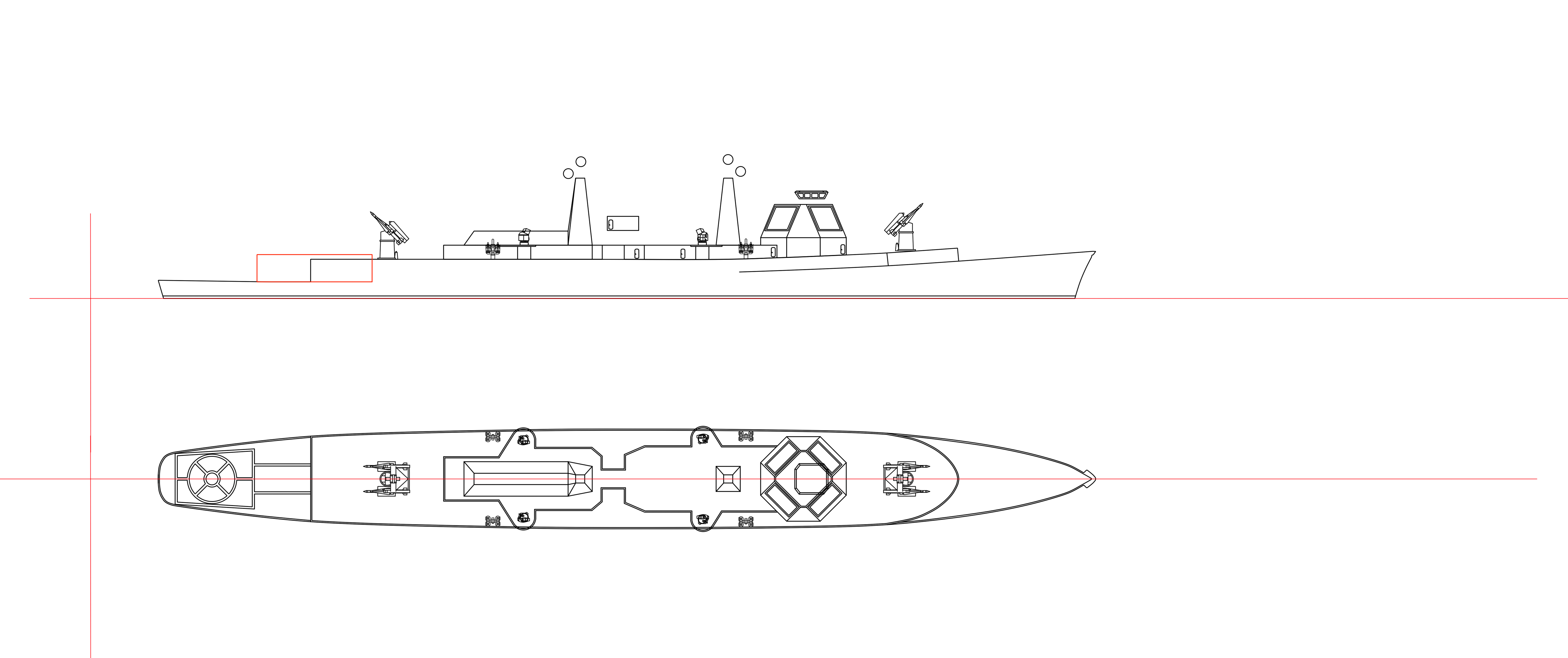
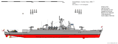
1) Based on the original drawings I think you can clean up the fantail, raise it by a deck and then have a helicopter hangar immediately aft of the aft NIGS launcher with its roof at the same height as the roof of the NIGS magazine/at the deck level of the NIGS launcher. This would give the empty two deck high space seen on the original drawings, that leads out onto the fantail - that I believe is space for a helicopter hangar. It would also give the ship a handsome, if bulky, flush deck appearance with the fantail following the line from the bow, which is what I think the drawings show.
Let me have a look at the plan again and I will get back to you. The blockhouse behind the NIGS magazine certainly seems too small to be a hangar. I would think at least a single Wessex would be desired.
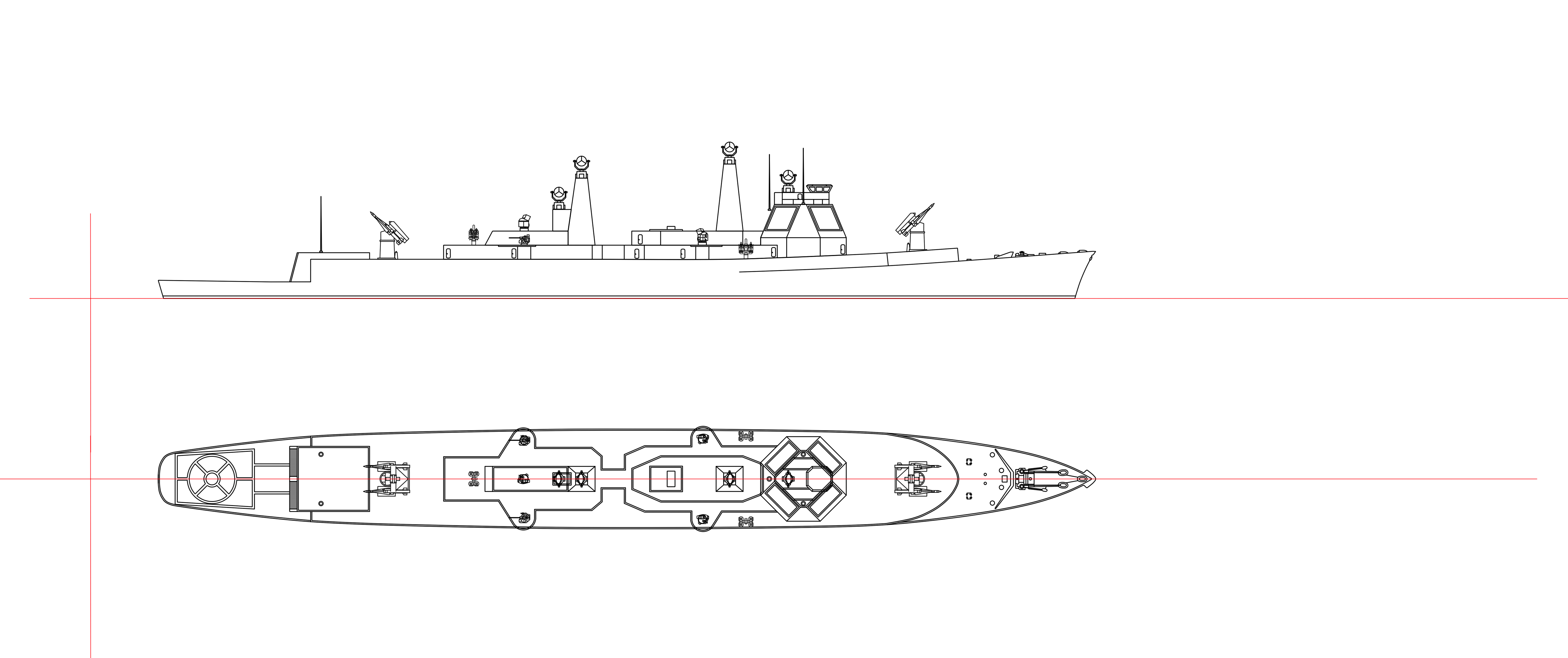
2) I think the radar blockhouse needs to be split in two given the comments about power going to both ends of the ship, the aft facing arrays either need to be between the funnels amidships or aft of the aft funnel, amidships seems most likely. Perhaps, in both scenarios, with the relevant (forward in my opinion) funnel integrated with the superstructure housing the radar? The amidships mast could be relocated to the forward superstructure and integrated with it in a way that eases placement of the directors? I also like the idea of angling the arrays 45 degrees from the centreline as in every post Tico AN/SPY-1D ship. Just as a reference point, I note that HMS Bristol actually has a highly angled bridge superstructure with only a very narrow forward facing section. In addition to potentially helping with interference from the launchers it would probably help with firing arcs. It might also be neccessary to raise thebidge and radar blocks by another deck.
Are the arrays you depict 20ft wide by 15ft high?
I was in two minds about a split or single blockhouse. Its frustrating that the snippets we have show nothing of any aft array block.
I have based this directly off the NIGS launcher plan which shows the fore edge of the superstructure block. It seems to indicate a flat angled front so I went with arrays parallel to the main axes of the ship. The base of the block seems to be 27ft assuming the bridge structure is the same width as the magazine block. That gives room for the array and 3.5ft of space around it on either side. Here comes the rub, if all the radar arrays are angled 45 degrees then the side panels will be angled back the same amount, the taper would soon prevent an array being fitted (I haven't calculated it but the edge of the top deck would be smaller than 20ft I would think).
So either; a) the drawing really is generic, b) your angled array argument makes more sense in that context.
If we go with the angled array approach its possible an aft block could be fitted just ahead of the aft funnel, perhaps becoming part of the radar block structure as a mack, would solve the rear illuminator problem too.
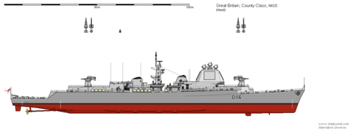
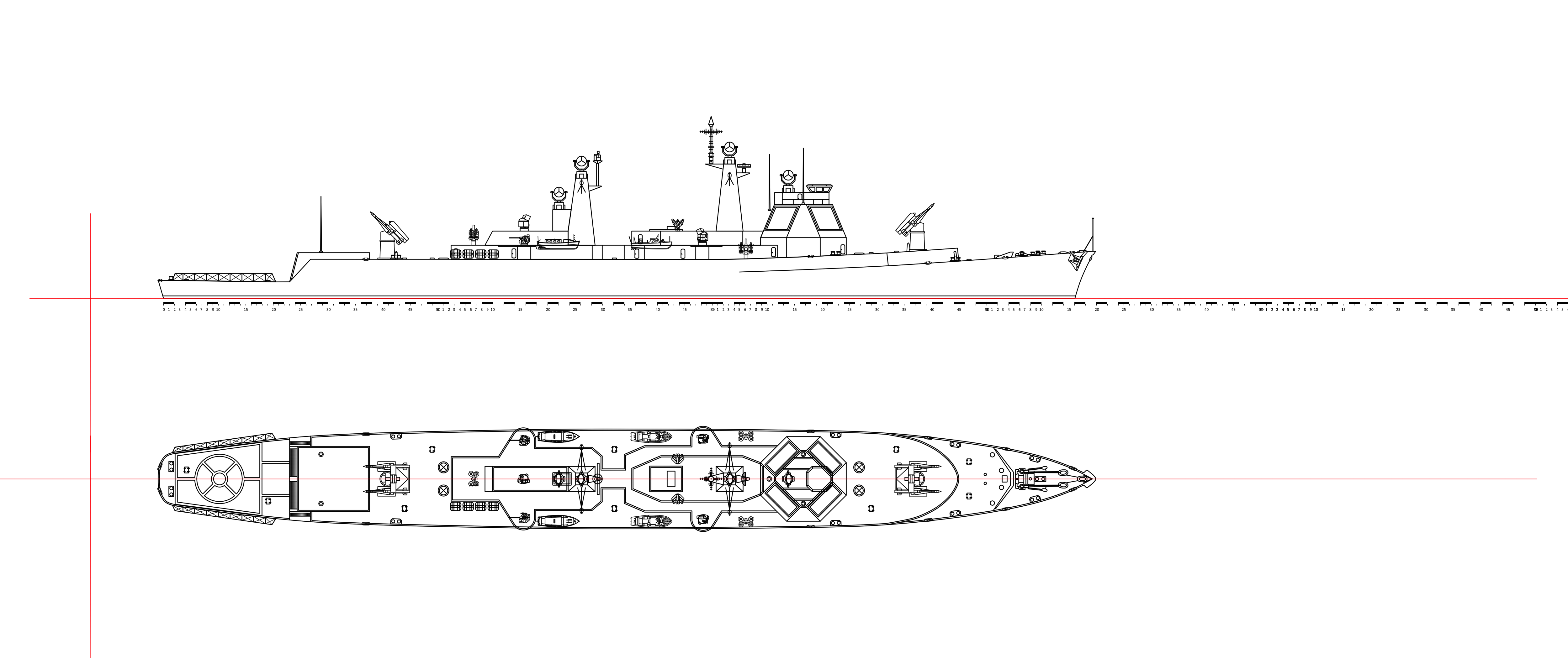
I have to admit I am not happy with the current layout, while plausible it feels too constrained, as you and Starviking point out the forward array seems too low and in general the fore and aft radars would cause problems, we're dealing with the most powerful naval radar Britain has contemplated and I feel it would need clearer arcs to avoid all kinds of problems. I have tried to reconstruct what the plan shows as a best guess to the designers intentions at that point in time. Its in no way an optimised NIGS destroyer/cruiser. But I will play around with the twin block idea some more.
Yes I began with 20 x 20ft but edited to 15ft high when you mentioned that in your recent post.
For those who don't know much about Shipbucket, the scale is 2 pixels = 1 foot, so here the arrays are 40 x 30 pixels.
Frankly I'm impressed, as I'm struggling again to turn anything out that doesn't take days of solid effort. Time I just don't have. A few hours here an hour there weeks will pass before I get anywhere.
Don't give up, it took me tinkering all week to produce this, much of the time was agonising over the details and getting them as plausible as possible.