
You are using an out of date browser. It may not display this or other websites correctly.
You should upgrade or use an alternative browser.
You should upgrade or use an alternative browser.
Sukhoi Su-57 / T-50 / PAK FA - flight testing and development Part I [2010-2012]
- Thread starter Matej
- Start date
- Status
- Not open for further replies.
saintkatanalegacy
Little Miss Whiffologist
- Joined
- 31 March 2009
- Messages
- 718
- Reaction score
- 9
in the available illustration only 1 of the blocker components can be seen though I assumed 2 at different angles in this particular render
also, in case you haven't heard
there's a "pi" in radio waves
also, in case you haven't heard
there's a "pi" in radio waves
flateric said:one can think that compressor fan blades are strictly perpendicular to coming radar waves...
So long as parts of te edges of the fan blades are perpendicular to incoming radar wave, it will reflect some of the radar photons straight back towards the emitter, the same with this blocker. If this blocker is set perpendicular to a straight intake path, then this so called blocker will itself reflect radar energy back to the emitter. So I don't think this component works.
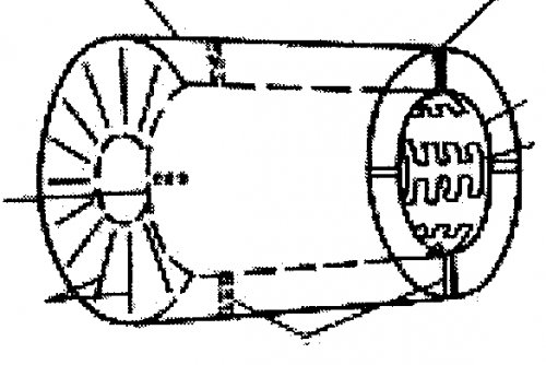
In the latest issue of Aviation week, there is an illustration of a Japanese two spool turbofan design with integral radar blocker for a ATD-x followon. The blocker consists of three components. The first is a set of flat radial vanes with strongly swept back leading edge so their leading edges are not perpendicular to incoming radar waves and do not reflect radar waves straight back along the direction it came from. The second component is a set of deep, strongly curved radial vanes that shields the fan face and forces any air or radar wave traveling down the intake to take a s-turn before reaching the fan. The last component is a third set of thin radial vanes, probably to smooth or condition the airflow before it actually hit the fan face. It appears that in this design, the blocker completely obscures the fan face when viewed straight down the intake.
Spring
ACCESS: Confidential
- Joined
- 4 June 2008
- Messages
- 92
- Reaction score
- 0
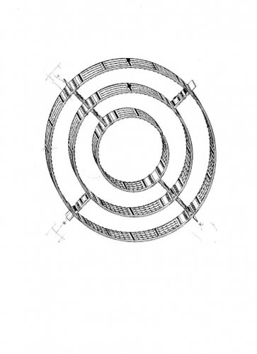
Is this blocker an electromagnetic device? I have seen what seems to be the patent drawing , and it does have weird incriptions over the inner surface, and other weird lines through the circles...the inner surface is weird covered with many pins, the outer surface seems to be the wiring of all of them...
I have not seen any other blocker with such kind of incriptions and details, the plasma thing attacks again?
I have not seen any other blocker with such kind of incriptions and details, the plasma thing attacks again?
Spring
ACCESS: Confidential
- Joined
- 4 June 2008
- Messages
- 92
- Reaction score
- 0
It seems to me any plasma trying to make stealth won't last long in the fast moving
Actually that fast moving air is needed to generate ionization, much like the plane antennas, the problem is the dispertion, which should not be a problem in the air duct.
This is the drawing, this thing is not a blocker IMHO, is probably a excitation circuit, but this is a wild especulation from me...although must say definitively is not a 'blocker'
Attachments
saintkatanalegacy
Little Miss Whiffologist
- Joined
- 31 March 2009
- Messages
- 718
- Reaction score
- 9
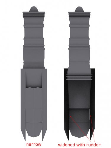
but really though, you'd be able to "block" off radio waves optimally once 2 of these forms "crescents" from the front though it is said that this device would be even longer
- Joined
- 1 April 2006
- Messages
- 10,730
- Reaction score
- 6,760
whatever you think, drawing is authentic, but it shows just a part of blocker, which has its lenght roughly equal to its diameterSpring said:This is the drawing, this thing is not a blocker IMHO, is probably a excitation circuit, but this is a wild especulation from me...although must say definitively is not a 'blocker'
Spring
ACCESS: Confidential
- Joined
- 4 June 2008
- Messages
- 92
- Reaction score
- 0
saintkatanalegacy said:but really though, you'd be able to "block" off radio waves optimally once 2 of these forms "crescents" from the front though it is said that this device would be even longer
I would like to see how this thing is, probably you will be able to see the engine's face through this device, what I'm saying is that it looks like this 'blocker' is not a conventional one, i.e., fitting a molded material covered with RAM, or a glass fiber matrix stuffed with meshes (or a combination of both), which I have been told blockers are made with.
This devide is active , at least i can tell from this segment, it has even it connectors...
saintkatanalegacy
Little Miss Whiffologist
- Joined
- 31 March 2009
- Messages
- 718
- Reaction score
- 9
I'm not actually disagreeing with you...
I'm just assuming that the device is paired such that the "blocking" via what you described is at optimal coverage by experimenting a bit with different angles such that they're not mirror images
but for the sake of keeping things simple, we just refer to it as a "blocker" or an active "blocker"
I'm just assuming that the device is paired such that the "blocking" via what you described is at optimal coverage by experimenting a bit with different angles such that they're not mirror images
but for the sake of keeping things simple, we just refer to it as a "blocker" or an active "blocker"
Flateric,
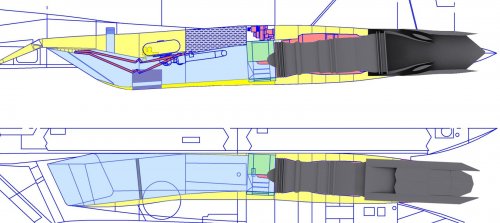
You have recently mentioned on a keypubs posting that prototype 50-3 will have many external differences compared to prototype 1 & 2 (presumably to incorporate much of the stealth treatments). Any idea if they plan to change the moldline of side aspect (towards the aft) to cater to those circular engine housings (which are bad for side aspect RCS)?
Or would that change only with the introduction of those stage 2 engines with flat nozzles (supposedly 8-10 years down the line) ?
IMO, It doesnt make sense if - all that attention paid in side aspect (chining of rear beavertail, reduced size of vertical fins, diamond shaped intakes) is ruined by those circular engine housings.
saintkatanalegacy
Little Miss Whiffologist
- Joined
- 31 March 2009
- Messages
- 718
- Reaction score
- 9
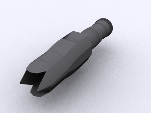
if they'll modify the aft section... it'll probably be at 26° angles and have to extend it to accommodate the unusually long ejector flat nozzles...
I wouldn't even be surprised if the aft moldlines for the engine will somehow "resemble" the YF-23 since the bottom(and probably even the top) area of the ejector seems to be flat as well based on the illustration I posted earlier
I wouldn't even be surprised if the aft moldlines for the engine will somehow "resemble" the YF-23 since the bottom(and probably even the top) area of the ejector seems to be flat as well based on the illustration I posted earlier
- Joined
- 1 April 2006
- Messages
- 10,730
- Reaction score
- 6,760
oh, did I really?sanjeev.k said:You have recently mentioned on a keypubs posting that prototype 50-3 will have many external differences compared to prototype 1 & 2
") I said nothing of 'many external differences'
I said nothing of 'many external differences'moreover, many differences will be take precautions of for us to not see 'em soon
how EMD T-50 will look like, I don't know
Well, actually, - I was referring to this post of yours -> http://forum.keypublishing.co.uk/showthread.php?t=103947&page=28flateric said:oh, did I really?sanjeev.k said:You have recently mentioned on a keypubs posting that prototype 50-3 will have many external differences compared to prototype 1 & 2
moreover, many differences will be take precautions of for us to not see 'em soon
how EMD T-50 will look like, I don't know
#######
50-2 - almost no external differences
most interesting things will start with 50-3...
######
saintkatanalegacy
Little Miss Whiffologist
- Joined
- 31 March 2009
- Messages
- 718
- Reaction score
- 9
I think what he meant was the avionics etc.
there's not much point in changing the aft section until the 2nd phase engine is ready
other than that, might look forward to changes in panel alignments for a "stealthier" form
there's not much point in changing the aft section until the 2nd phase engine is ready
other than that, might look forward to changes in panel alignments for a "stealthier" form
- Joined
- 2 January 2006
- Messages
- 3,524
- Reaction score
- 3,121
EDIT:
Can anyone confirm ... or even has some pictures !??
Reportedly T-50-2 had today its maiden flight:
http://lenta.ru/news/2011/02/23/pakfa/
Reportedly a "mistake" from an Interfax-reporter ... flight will be tomorrow or even in two days.
Deino
Can anyone confirm ... or even has some pictures !??
http://lenta.ru/news/2011/02/23/pakfa/
Reportedly a "mistake" from an Interfax-reporter ... flight will be tomorrow or even in two days.
Deino
saintkatanalegacy
Little Miss Whiffologist
- Joined
- 31 March 2009
- Messages
- 718
- Reaction score
- 9
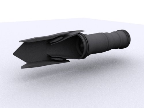
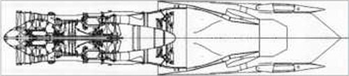
I made a mirror image of turbine+nozzle pic I posted before, modeled it and assumed that the panel would be aligned at 26°(general vertical alignment) since the top and bottom would be flat
after comparing it with paralay's drawing... I find it disturbingly convenient for its size :-\
after comparing it with paralay's drawing... I find it disturbingly convenient for its size
:-\Attachments
saintkatanalegacy
Little Miss Whiffologist
- Joined
- 31 March 2009
- Messages
- 718
- Reaction score
- 9
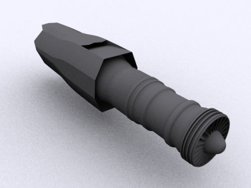
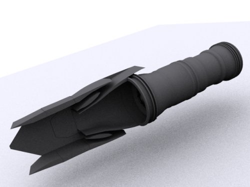
it's not surprising that the ejector flat nozzle would be huge if you've seen the flanker that's been fitted with one...
but, it really does make you think how they will manage the change in center of gravity if ever the nozzles become outrageously heavy
but, it really does make you think how they will manage the change in center of gravity if ever the nozzles become outrageously heavy
- Joined
- 3 June 2011
- Messages
- 17,332
- Reaction score
- 9,070
saintkatanalegacy said:it's not surprising that the ejector flat nozzle would be huge if you've seen the flanker that's been fitted with one...
But what's the point of it? I thought ejectors went out of fashion in the 60s?
saintkatanalegacy
Little Miss Whiffologist
- Joined
- 31 March 2009
- Messages
- 718
- Reaction score
- 9
IR emission reduction most probably... though I'm still wondering about the drag penalty associated with ejector nozzle design...
but hey, even a certain man from australia thinks it's viable for the PAK-FA
but hey, even a certain man from australia thinks it's viable for the PAK-FA
- Joined
- 3 June 2011
- Messages
- 17,332
- Reaction score
- 9,070
saintkatanalegacy said:IR emission reduction most probably... though I'm still wondering about the drag penalty associated with ejector nozzle design...
but hey, even a certain man from australia thinks it's viable for the PAK-FA
Oh, well then it must be good.
saintkatanalegacy
Little Miss Whiffologist
- Joined
- 31 March 2009
- Messages
- 718
- Reaction score
- 9
I dunno... could be similar to this though...
http://www.flodesign.org/pdf/AIAA20020230.pdf
http://www.flodesign.org/pdf/AIAA20020230.pdf
- Joined
- 3 June 2011
- Messages
- 17,332
- Reaction score
- 9,070
saintkatanalegacy said:I dunno... could be similar to this though...
http://www.flodesign.org/pdf/AIAA20020230.pdf
Reminds me of the ejectors on the F-111. I wonder how much they actually got from them vs the TF-30s on the Tomcat (same engine, no ejectors).
saintkatanalegacy
Little Miss Whiffologist
- Joined
- 31 March 2009
- Messages
- 718
- Reaction score
- 9
gonna add this one:
http://www.grc.nasa.gov/WWW/RTE/docs/reno2004.pdf
http://www.grc.nasa.gov/WWW/RTE/docs/reno2004.pdf
Dreamfighter
'Senior Something'
- Joined
- 13 July 2008
- Messages
- 399
- Reaction score
- 384
This flat nozzle-design, is it supposed to vector in yaw as well as in pitch? I think it is 2D-TVC, but I'm not sure...
There seems to be flaps on the top and bottom that could in theory direct the exhaust in pitch, but no appearent flaps on the side to direct the exhaust in yaw. Another possibility, maybe this nozzle is meant to hide afterburner plume? Maybe PAK-FA is intended to engage its afterburner routinely in dog fighting ranges where IR missiles might be a serious threat so this nozzle reduces its vulnerability?
saintkatanalegacy
Little Miss Whiffologist
- Joined
- 31 March 2009
- Messages
- 718
- Reaction score
- 9
Given that any inward deflection of yaw flaps must get in the way of inward deflection of pitch flaps, and vice versa, it's hard to see how the yaw flaps and pitch flaps can deflect at the same time. So it's either VTC in pitch or in yaw, not both at same time.
Avimimus
ACCESS: Top Secret
- Joined
- 15 December 2007
- Messages
- 2,234
- Reaction score
- 499
chuck4 said:There seems to be flaps on the top and bottom that could in theory direct the exhaust in pitch, but no appearent flaps on the side to direct the exhaust in yaw. Another possibility, maybe this nozzle is meant to hide afterburner plume? Maybe PAK-FA is intended to engage its afterburner routinely in dog fighting ranges where IR missiles might be a serious threat so this nozzle reduces its vulnerability?
It could be intended to hide the normal jet exhaust plume. If they use a more powerful engine there may still be an acceptable thrust ratios without afterburner. The Russian analysis might value IR stealth more highly. One has to remember that the primary goal of radar stealth was originally to make it easier to penetrate and survive in proximity to surface-to-air missile batteries - not aerial combat. At the medium ranges that air-combat tends to take place at infra red signature may come into play.
For example, if a T-50 was stealthy enough to prevent a firing solution until it was within about 40km of an F-22, and the F-22 flew with afterburner or had used up its five minute cooling system - the American fighter wouldn't be that much harder to hit than any other fighter. Perhaps the PAK-FA is designed to combine survivability at medium range (supersonic maneuverability and stealthy features) until its low IR signature, sensor suite and other qualities gives it a strong advantage?
Aren't the nozzles announced to be only 2d TVC? Or is this an attempt to confuse us
Dreamfighter
'Senior Something'
- Joined
- 13 July 2008
- Messages
- 399
- Reaction score
- 384
chuck4 said:So it's either VTC in pitch or in yaw, not both at same time.
Well, that was what I was wondering about: not full 3D like on the Su-27 derivatives, but the possibility to incorporate non-simultaneous pitch- and yaw-vectoring in such a flat nozzle (though that may make it more complex/heavy).
saintkatanalegacy
Little Miss Whiffologist
- Joined
- 31 March 2009
- Messages
- 718
- Reaction score
- 9

- Joined
- 1 April 2006
- Messages
- 10,730
- Reaction score
- 6,760
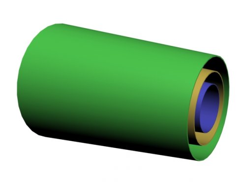
some cylinders just needn't to be as long as external one to trap waves...and external one can consist of several shorther ones...as I said, zillion variants, but idea of wave trap is clear
saintkatanalegacy
Little Miss Whiffologist
- Joined
- 31 March 2009
- Messages
- 718
- Reaction score
- 9
word from Groomi: "stay tuned tomorrow or the day after tomorrow"
http://groomi.livejournal.com/33229.html
http://groomi.livejournal.com/33229.html
- Joined
- 3 June 2011
- Messages
- 17,332
- Reaction score
- 9,070
flateric said:50-2 has performed first taxi tests today
Pics?
- Status
- Not open for further replies.
Similar threads
-
 Sukhoi Su-57 / T-50 / PAK FA - flight testing and development Part II [2012-current]
- Started by overscan (PaulMM)
- Replies: 3K
-
 Sukhoi Su-57 / T-50 / PAK FA first flight - pictures, videos and analysis [2010]
- Started by flateric
- Replies: 872
-
Sukhoi PAK FA news and speculation (T-50, I-21) Part II [2008-2009]
- Started by overscan (PaulMM)
- Replies: 451
-
Sukhoi PAK FA news and speculation (T-50, I-21) Part I [2006-2008]
- Started by overscan (PaulMM)
- Replies: 455
-
Vladimir Sergeevich Ilyushin 31-03-1927 - 01-03-2010
- Started by flateric
- Replies: 4