Merriman's Submarine Modelling Masterclass

[best David Attenborough narrator's soto-voice:]

Here, we observe the chance meeting of two members of genus "Subaquaneam Caeruleam Tunicam", literally, the "Blue Shirted Submariner".

Gazing warily from a distance, the two will circle cautiously while issuing intricate vocal challenges and responces, much like the US Robotics Modem of yore negotiated baud and encoding protocol handshakes. Results can be varied, ranging from protocol failure resulting in an incapacitated Shore Patrol and a wrecked alcohol dispensary, to a high PRF encoding lock leading to a life-long friendship cemented by similar experiences.

Which will result from this encounter? Let's keep our voices down as our cameras attempt to record this rarely witnessed ritual in the wild Internet...
 
Last edited:
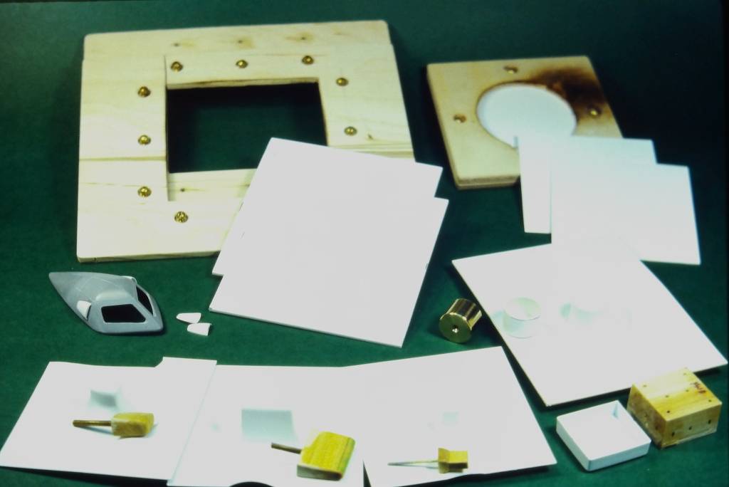
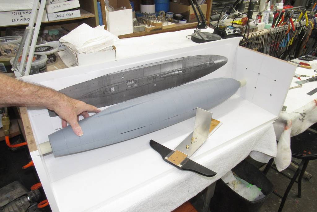
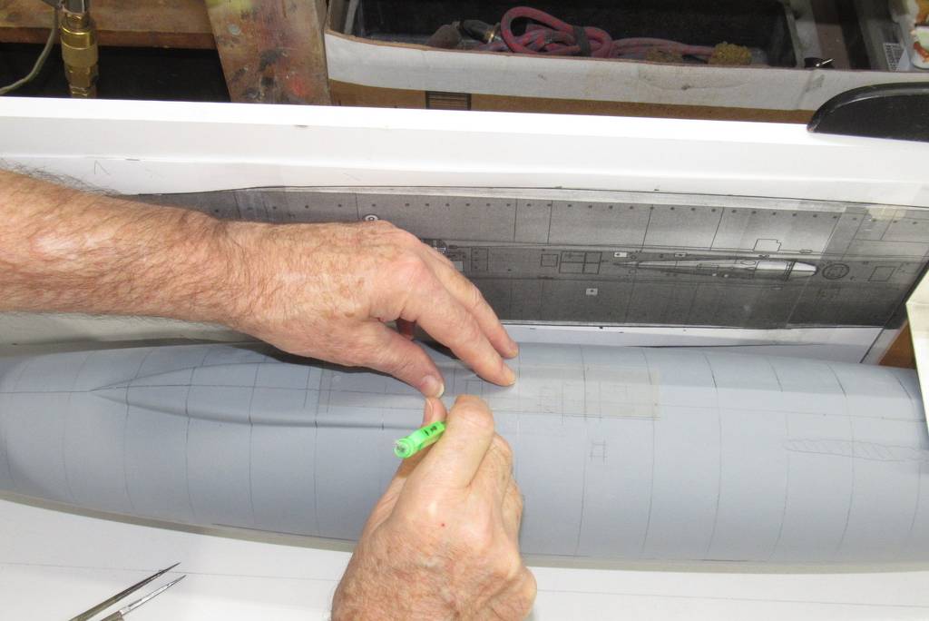
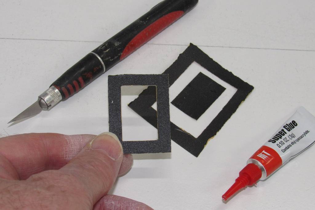
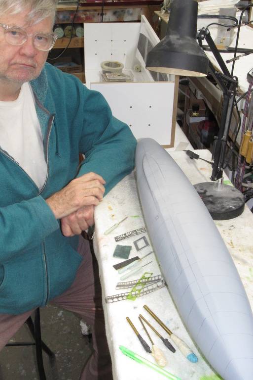
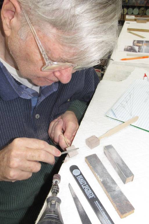
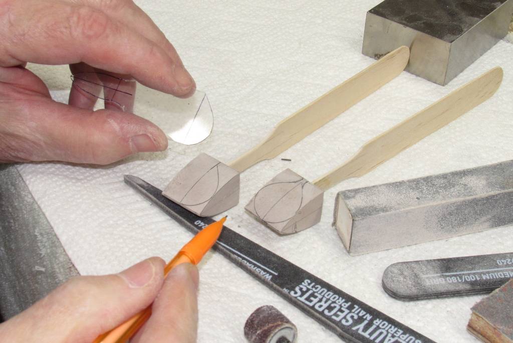
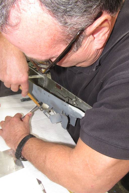
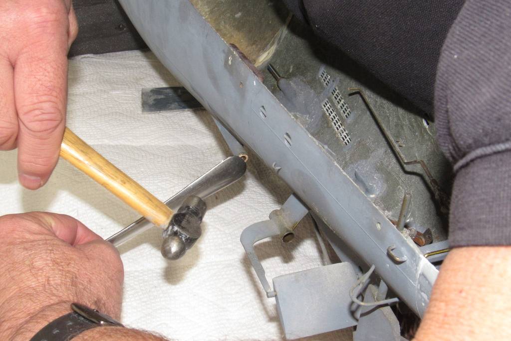
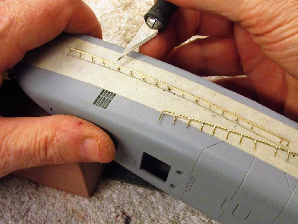
As always: I love studying your photos, to see what tips and tricks I can pick up. Loved seeing the sandpaper applied to certain key areas, on the latest editions of your waterline marking tool; and the brass marking-device-holding clamps, too. And lots of other clever stuff, in other places, too.

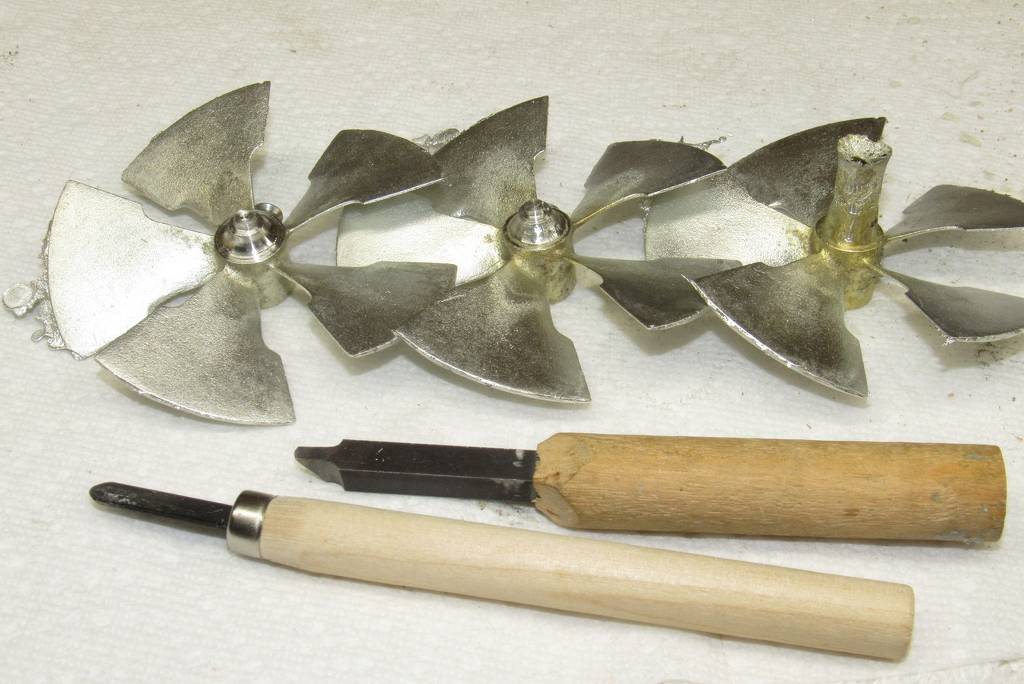
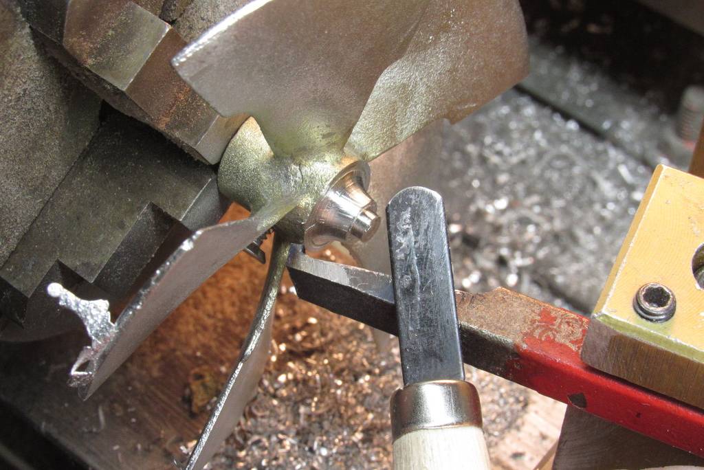
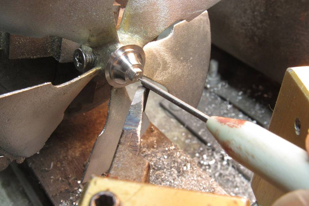
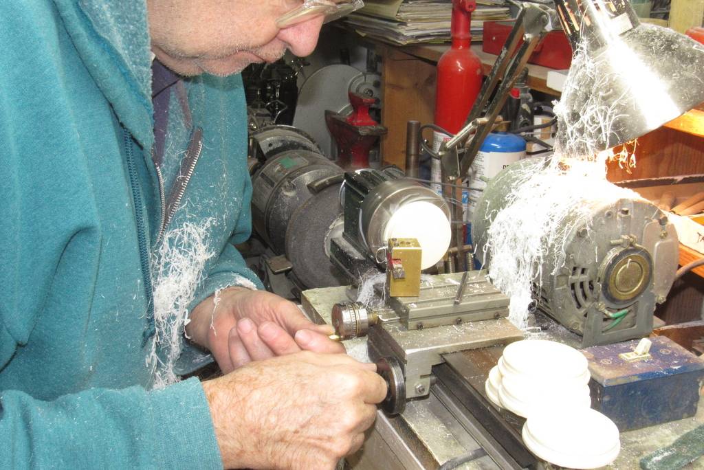
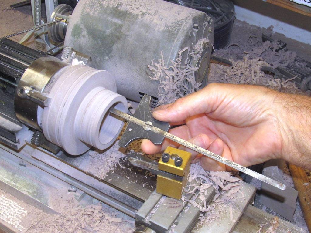
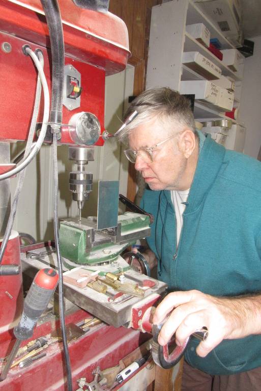
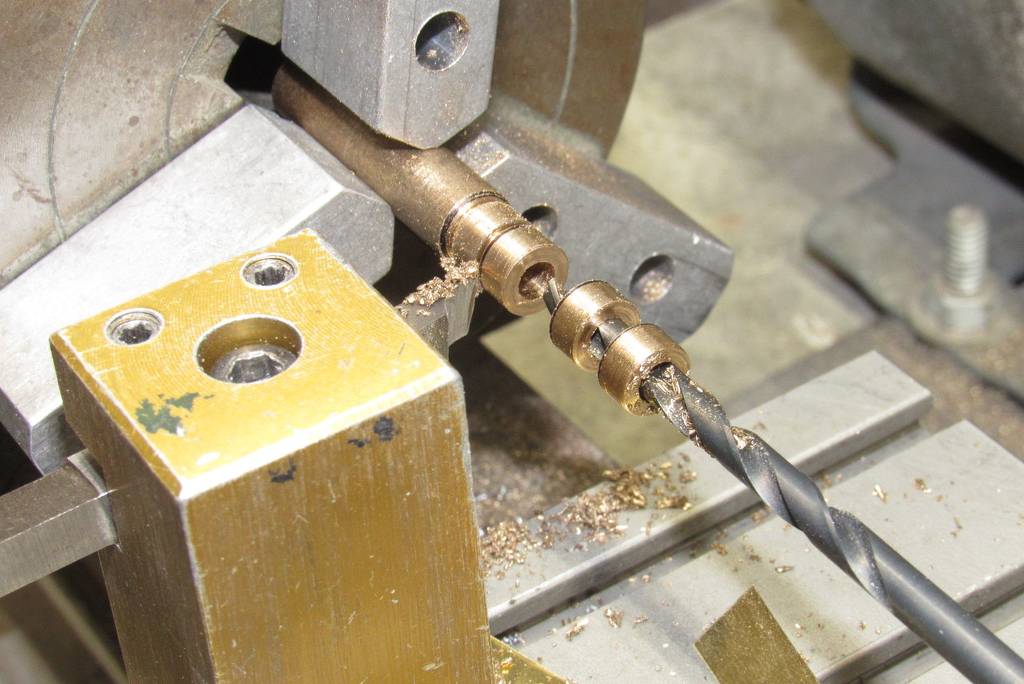
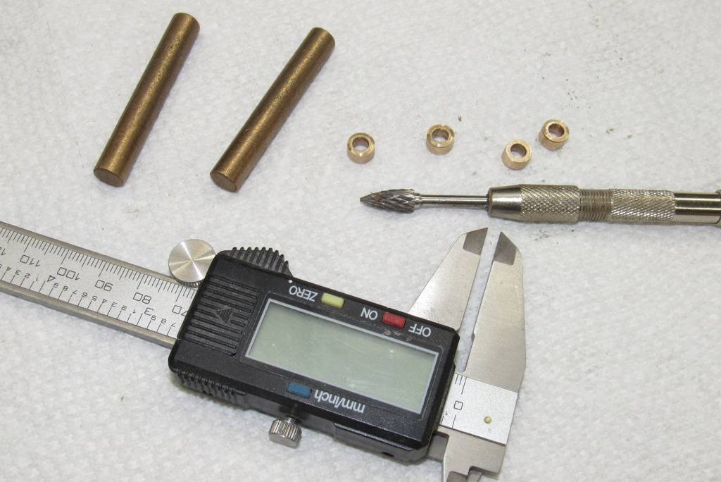
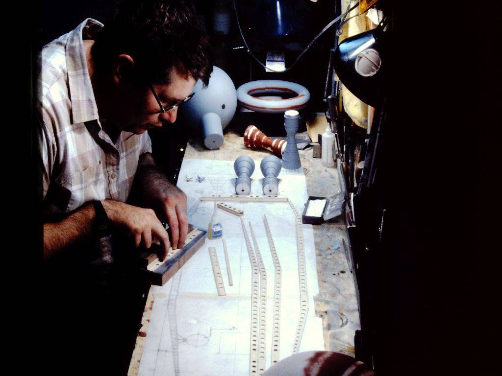
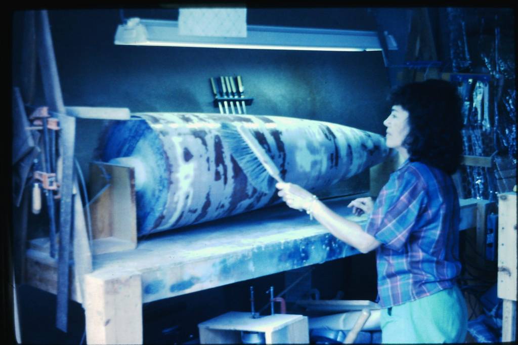
About those lathe pics, from a page back ... any chance of seeing (if / whenever you see fit, time-wise) some close-up pics on the hand-operated, wooden-handled lathe tools that you made?

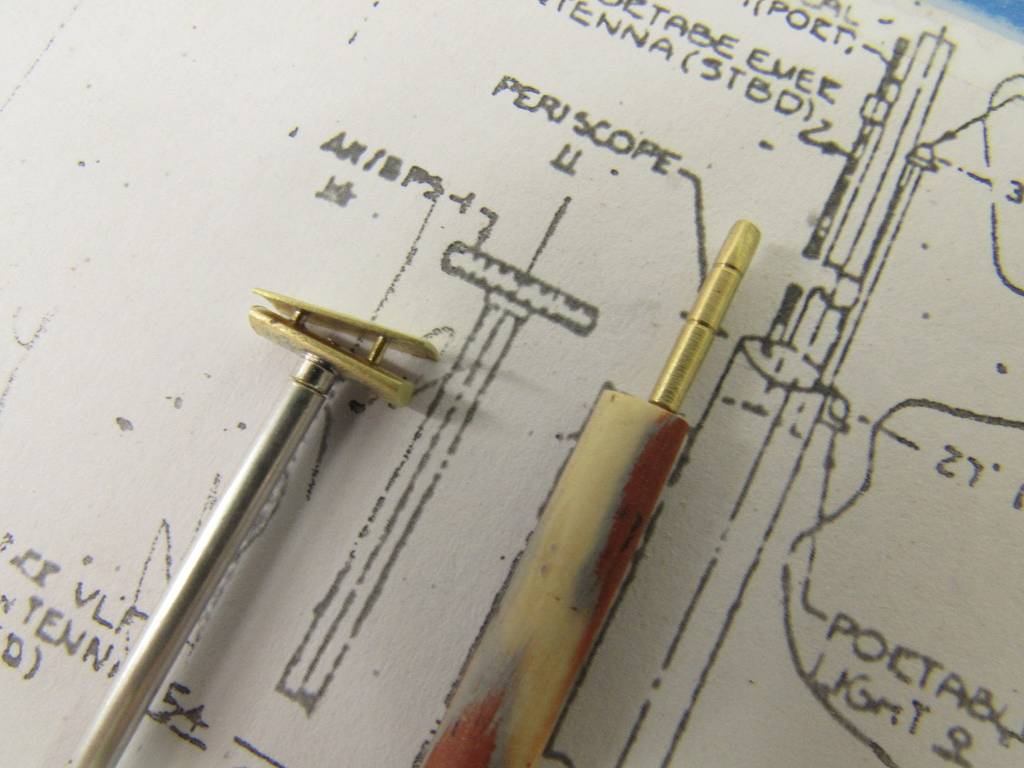
I realize they're for use with a "wood lathe" style of lathe, where the operator holds the cutting devices in his hands; but I'm guessing the metal portions were (perhaps?) originally meant for or were from a metal-cutting (or screw-cutting) style lathe? With the heads on them shaped as you pleased, edge-wise; but then instead of mounting them in a permanently-affixed tool-holder, on a metal-cutting style of lathe, you used those pieces as hand tools, instead? Or am I totally wrong on that? Was it some other kind of steel you used, for the metal portions of those cutting tools?

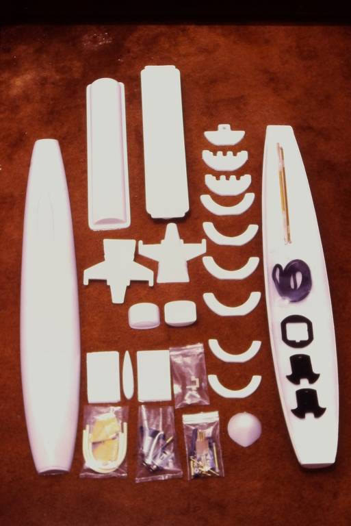
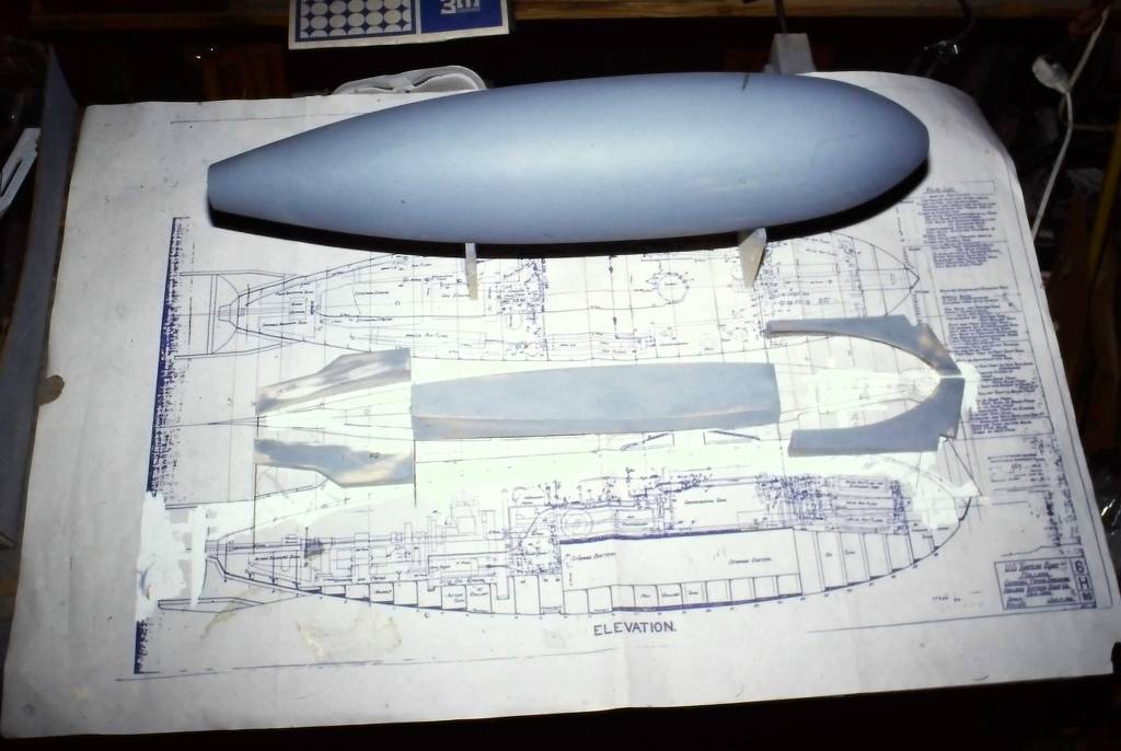
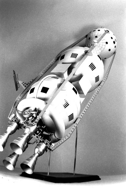
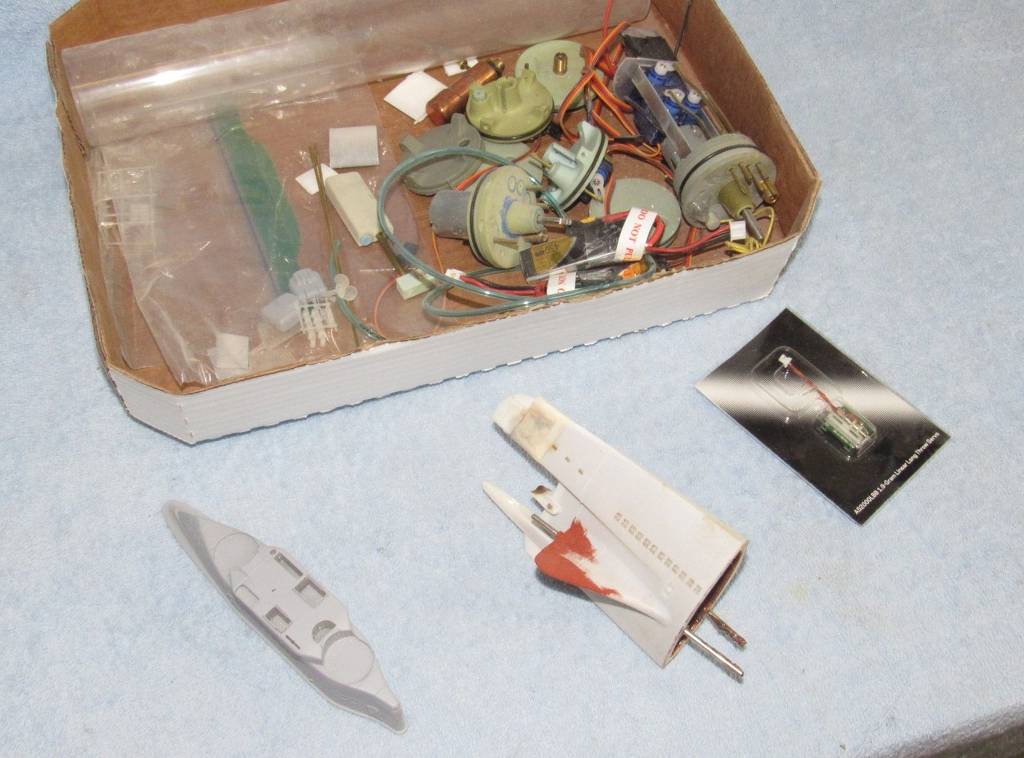
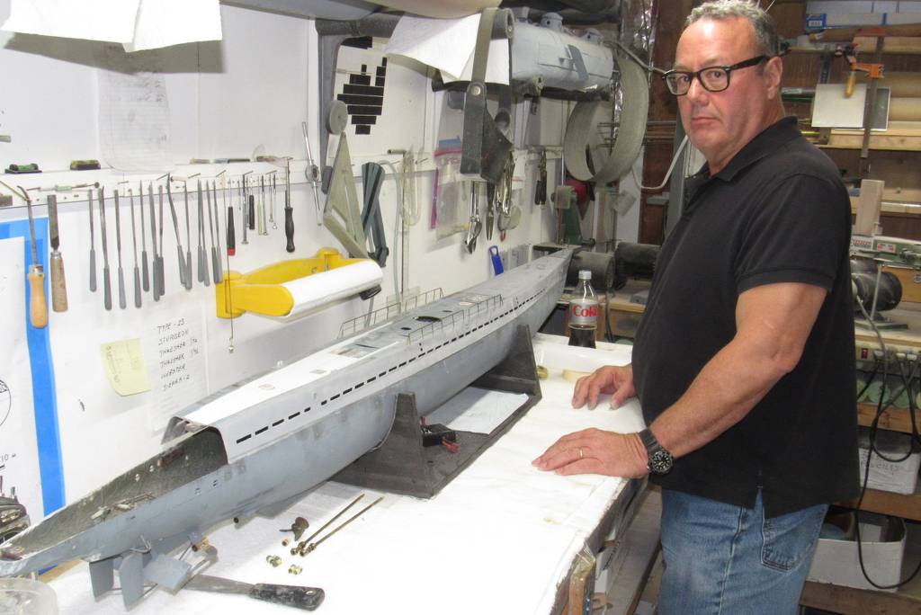
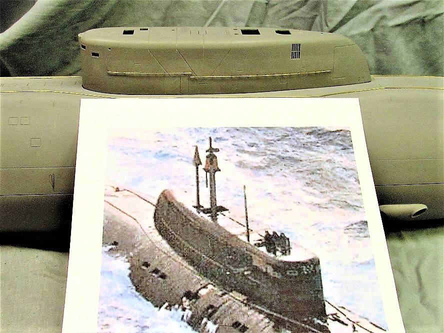
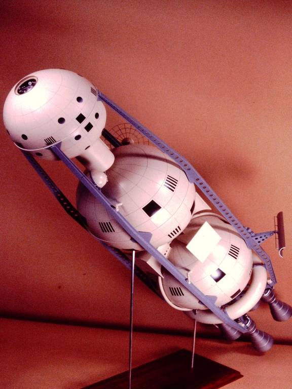
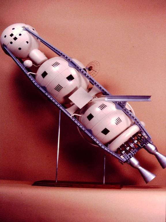
As an aside: All of this very cool sub-stuff I'm seeing had me looking through storage totes, to see if my memory was right, about how far I had once gotten, on "figuring out the shape" of a fun little submarine design by Bill Campbell, of "Weird-Ohs" model kit fame, from a decade or so ago, now. (Geez! Has it been that long?!) It made me feel like, if I wasn't already on deadline for a completely different project, I'd be giving Dunkvasser's sub model another long look; and maybe working on that one, again. Oh well. I guess I'll have to resurrect that project, at some other time. But it felt good just to get out the pieces, and remember how far along I'd gotten.

Thanks for posting all of this assorted coolness, sir!
 
I had the same question that Scott Kenny did -- but I'm assuming it's likely the latter choice, due to the flux canister being seen in the images; and what looks like a length of solder, sitting near the area of the presumed joint. (But with you, David, one never knows what cleverness lurks in the hearts of some people, etc., and how many tasks a smart person can simultaneously do!?)

Thanks much for those photos of those hand-held lathe tools! That was a glorious explanation! I especially loved seeing what I'm presuming is a dedicated o-ring groove cutter (adjustable for final cut-depth, apparently) being used, with what my Ye Olde Machinist's Training tells me is the lathe's actual intended cutter; but being used as a tool rest, instead! (Like I said: "Cleverness Overload"!)
 
Brass electroplating those axe-head screws? Or is that soldering a new blade into the old one?
Replacing a blade that popped off. (If I had done a proper soldering job in the first place, this would not have been necessary).

Yeah, that's my partner in crime, Jake, resistive soldering a replacement blade into the hub. Using this technique localizes the heat at the joint. The rest of the work remains at room temperature, so we didn't have to suffer lifting of the surrounding putties, primer or paint.
 
I had the same question that Scott Kenny did -- but I'm assuming it's likely the latter choice, due to the flux canister being seen in the images; and what looks like a length of solder, sitting near the area of the presumed joint. (But with you, David, one never knows what cleverness lurks in the hearts of some people, etc., and how many tasks a smart person can simultaneously do!?)

Thanks much for those photos of those hand-held lathe tools! That was a glorious explanation! I especially loved seeing what I'm presuming is a dedicated o-ring groove cutter (adjustable for final cut-depth, apparently) being used, with what my Ye Olde Machinist's Training tells me is the lathe's actual intended cutter; but being used as a tool rest, instead! (Like I said: "Cleverness Overload"!)
Correct on all counts, Ward.

(For those looking over our shoulders, Ward is one hell of a model builder himself, and we have been kicking projects around for decades).

David
 
Replacing a blade that popped off. (If I had done a proper soldering job in the first place, this would not have been necessary).

Yeah, that's my partner in crime, Jake, resistive soldering a replacement blade into the hub. Using this technique localizes the heat at the joint. The rest of the work remains at room temperature, so we didn't have to suffer lifting of the surrounding putties, primer or paint.
Never did any resistive soldering... electrical via iron, silver via MAPP gas back in the day.
 
The winged rocket--an original creation?
We were a second-party contractor to build two exhibit models for the IBM Blueprint for Space exhibit. The big three-stage ferry rocket and the moon reconnaissance orbiter, both von Braun designs from the Viking books and Collier's articles. Here's more photos of that work:


That's a surprisingly small subdriver unit inside the WW2 boat. I was expecting a much larger central ballast tank.
 
That's a surprisingly small subdriver unit inside the WW2 boat. I was expecting a much larger central ballast tank.

When I surveyed the above waterline portions, I was delighted to find that most structures were of thin wall thickness -- as ballast weight has to equal above waterline displaced water weight, I only needed 60 ounces of water to get the boat to near neutral trim submerged.

(As the specific gravity of GRP is close to 1 all I had to do was weigh the above waterline structures -- fortunately the hull split was at the waterline -- add ten percent for slop, and I had the needed weight of ballast water. The length of the ballast tank cylinder was adjusted to hold that weight of water).


With the kind permission of this sites Administrator, I'm announcing a zoom meeting next Saturday at the Nautilus Drydocks forums. Something that may be of interest to you.

Specifically, I'll be presenting an illustrated talk about the advantages, processes, materials, and tools of plastic sheet thermoforming.

The DIVE TRIBE zoom meetings are a bi-monthly event and feature topics that are focused on the construction and operation of static and radio-controlled model submarines. However, the presentations and general discussion are also of value to advanced model kit assemblers and scratch-builders alike.

Heads up though: a year's subscription to these zoom meetings -- in which all hands can, and are encouraged, to participate -- is for DIVE TRIBE members only. That fee will put you back fifty-bucks.

However, if you want a taste of what we do without a hit to your pocketbook, our fearless DIVE TRIBE leader, Bob Martin, has posted over at YouTube a recent and complete zoom meeting.

View: https://youtu.be/kzzdmoMPCZM


If you want to join the DIVE TRIBE, here's how:


Here are some of the photos that will be accompanying Saturdays presentation:


So, let me see if I'm following your workflow here. You carved one each screw blade (one for each direction of rotation), cast 3 each. Now you're installing cast blades on master hubs to make a larger single casting?
 
So, let me see if I'm following your workflow here. You carved one each screw blade (one for each direction of rotation), cast 3 each. Now you're installing cast blades on master hubs to make a larger single casting?
Perfect, Scott. You got it right. Though, as a practical matter, I made more than three blade blanks per assembly.

Needed one to be a template to mark the blade root-hub interface, and another to serve as a template to cut the blades to a root profile that runs into the hub, but not long enough not block the hubs bore.

David
 

Similar threads

Back
Top Bottom