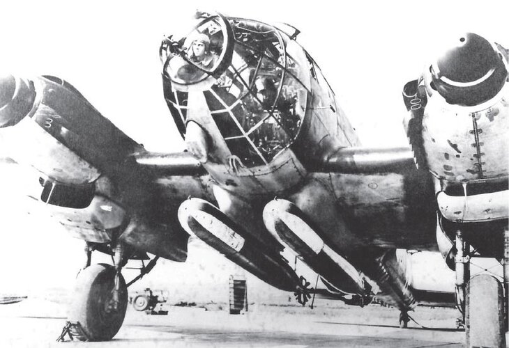
He-111 exhaust stack pipes/intakes

Prophet141

ACCESS: Confidential
Joined
25 April 2022
Messages
115
Reaction score
76
1696109683233.png
1696109544346.png

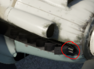
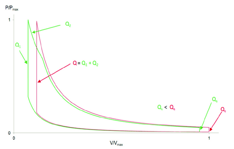
I've been talking to someone who pointed out the highlighted area on the He-111 H16's engine nacelles. They suspect it's designed to lower the pressure within the exhaust stacks, thereby increasing the efficiency of the Otto cycle as shown in the diagram below. The green lines represent a lower pressure in the exhausts. 1696110017462.png

Thanks, whatever the answer may be.
 
I've been talking to someone who pointed out the highlighted area on the He-111 H16's engine nacelles. They suspect it's designed to lower the pressure within the exhaust stacks, thereby increasing the efficiency of the Otto cycle as shown in the diagram below. The green lines represent a lower pressure in the exhausts.
Thanks, whatever the answer may be.
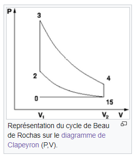
Otto Cycle? Normal for Heinkel engines ... French piston engines are Beau de Rochas cycle ... ;)


1696110874931.png
 
I don't see the relationship between the exhaust pressure and those cycles. In my view, these diagrams are propably showing a two stroke engine with the Otto and a halfway Seiliger process. In the pink one, all the heat is released at TDC and in the green one some of the heat is released at TDC and some later.

Please explain, how this pipes lowerd the back pressure. My idea is, that was propably a device to reduce the visibility of the exhaust flames.

BTW: the Austrians would call it Christian Reitmann cycle

 
Last edited:
The idea was that it would increase the velocity of the air flow through the exhaust and therefore lower the pressure. I had personally considered that it might have been to reduce the visibility of the exhaust.

The question is whether or not anybody has a concrete answer?
 
The idea was that it would increase the velocity of the air flow through the exhaust and therefore lower the pressure. I had personally considered that it might have been to reduce the visibility of the exhaust.

The question is whether or not anybody has a concrete answer?
Note that in a piston engine the expansion is volumetric. Not against a constant backpressure like in a gasturbine.
The volumetric expansion ratio is fixed by the engine design.
The pressure in the cylinder at end of expansion (at BDC) is much higher than ambient pressure.
Lowering the exhaust stub pressure would not lower the pressure inside the cylinder at BDC and therefor not effect power or efficiency.

(Adding a turbocharger could therefor generate additional power by expanding the cylinder exhaust further down to ambient pressure.
In the absence of a turbocharger the best way to make use of the cylinder exhaust pressure is to use ejector type exhaust stubs to maximise exhaust thrust.
)
 
The question is whether or not anybody has a concrete answer?

My best guess is that the pipes running through the exhaust stubs are heat exchangers.

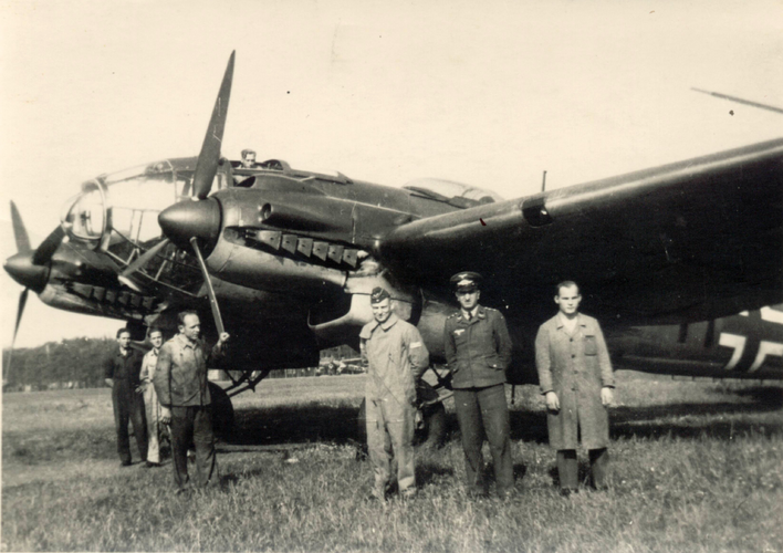
The photo below of a 111H torpedo bomber shows that the pipes are not round. I suppose to increase their surface area for heat transfer.

Cold ambient air enters by ram pressure and is warmed up by the hot exhaust for use as .................... (I don't really know).

H 111H torpedo bomber.jpg
 
Heating the inhabited spaces in the fuselage? (Just like my old Volkswagen.)
 
Heating the inhabited spaces in the fuselage? (Just like my old Volkswagen.)
And/or airframe de-icing . . .
EDIT: You are correct !
See HERE ( you will have to scroll down the page somewhat) :-


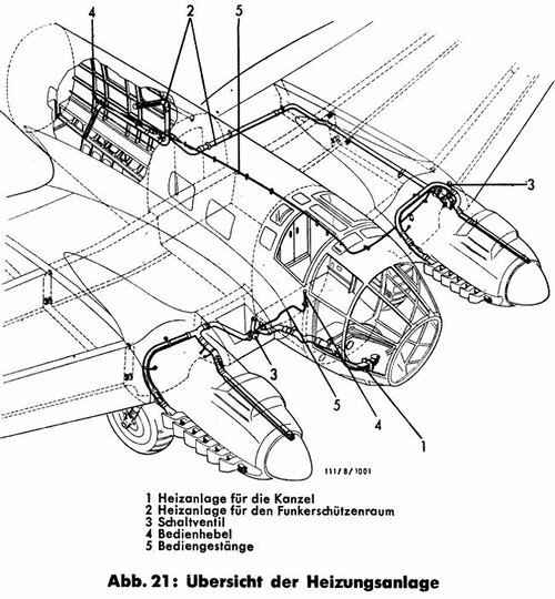
"A warm air heating system is available to heat the cockpit and the radio operator's room.
Fresh air is heated by the exhaust gases and led through pipes into the rooms to be heated. The heating is regulated from the cockpit and from the radio operator's room."
(machine translation)

Image0020.jpg


cheers,
Robin.
 
Last edited:
Note that in a piston engine the expansion is volumetric. Not against a constant backpressure like in a gasturbine.
The volumetric expansion ratio is fixed by the engine design.
The pressure in the cylinder at end of expansion (at BDC) is much higher than ambient pressure.
Lowering the exhaust stub pressure would not lower the pressure inside the cylinder at BDC and therefor not effect power or efficiency.

(Adding a turbocharger could therefor generate additional power by expanding the cylinder exhaust further down to ambient pressure.
In the absence of a turbocharger the best way to make use of the cylinder exhaust pressure is to use ejector type exhaust stubs to maximise exhaust thrust.
)

The first part is true, the in clyinder pressure is allways higher (at least at full load) than the ambient pressure.

The second part is not correct, the piston has to push out the exhaust gases and requires more work to do so with an increased back pressure.

I dind't believe in a heating system, since those pipes would rob a lot of power from the exhaust pulses and a cooling water based heating system is more logic on the first glance, but the air heating war less prone to damage and propably lighter.
 
I dind't believe in a heating system, since those pipes would rob a lot of power from the exhaust pulses and a cooling water based heating system is more logic on the first glance, but the air heating war less prone to damage and propably lighter.
I think, that heating system, based on warm air has one more advantage: it's easier to mount and maintain - even "leaks" of air in the junctions or due to damages doesn't made system unworkable. Literally, you couldn't loose working agent, just the overall heyating would decrease.
 
Well, that what I ment with less prone to damage...
Curiously, the same Heinkel company made He-100 fighter with vapour-cooling system. They definitely should decide, what stuff more vulnerable and important on aircraft: heating air or cooling water!
 
There is more to it than just the vulnerability, water cooling offers constant heat flow independently from the engine power and it doesn't require high temperature materials. Also, there is no inpact on exhaust thrust performance.
 
The first part is true, the in clyinder pressure is allways higher (at least at full load) than the ambient pressure.

The second part is not correct, the piston has to push out the exhaust gases and requires more work to do so with an increased back pressure.
I was merely trying to explain in a few lines to the topic starter that at the end of the power stroke (piston at BDC) the pressure in the cylinder is not affected by the pressure in the exhaust stubs. A Jumo 211 engine with a (volumetric) compression ratio of 6.5 (defined as: cylinder volume at BDC divided by cylinder volume at TDC) also has a volumetric expansion ratio of 6.5. That does not change if the exhaust stub pressure changes. His graph was not correct.
I agree that that is not the whole story. Apart from some power required to push out the exhaust gas, the exhaust stub pressure also has some impact on scavanging which will cost some power.

I was hoping that the heated air was used for something interesting, but now it turns out to be for cabin heating. That's a bit disappointing.
 
Pushing out the exhaust gases in a turbo charged engine requires quite a lot on energy.

The exhaust stacks could have had a positive or negative effect, depending on the lenght.
 
Pushing out the exhaust gases in a turbo charged engine requires quite a lot on energy.

The exhaust stacks could have had a positive or negative effect, depending on the lenght.
The stacks in the picture do not go to a turbo, those are short stacks straight off the cylinder head.

Stacks going to a turbo would have either a single exhaust point or a pair of exhausts, one large for the turbo and one small for the wastegate.
 

Similar threads

Back
Top Bottom