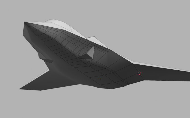
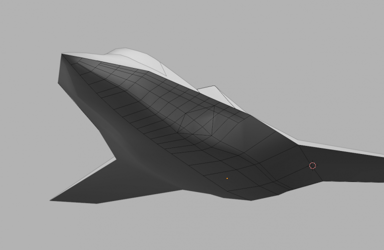
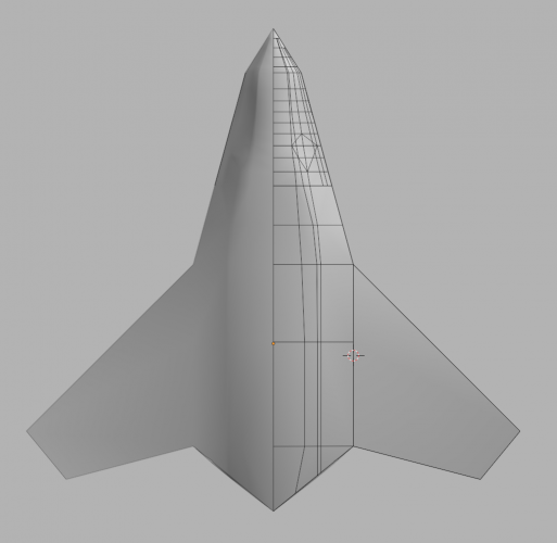
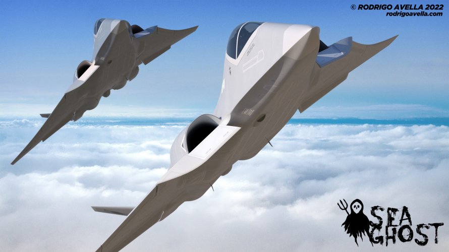
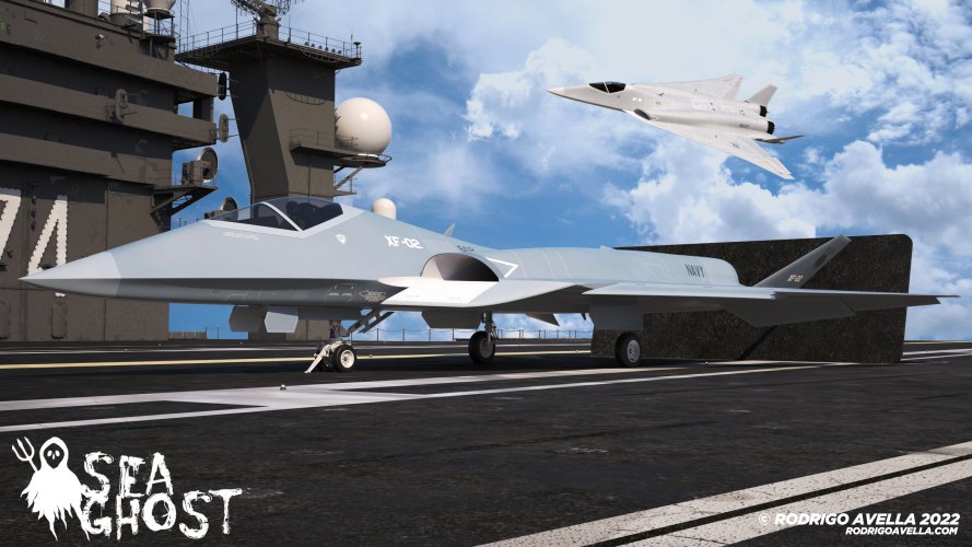
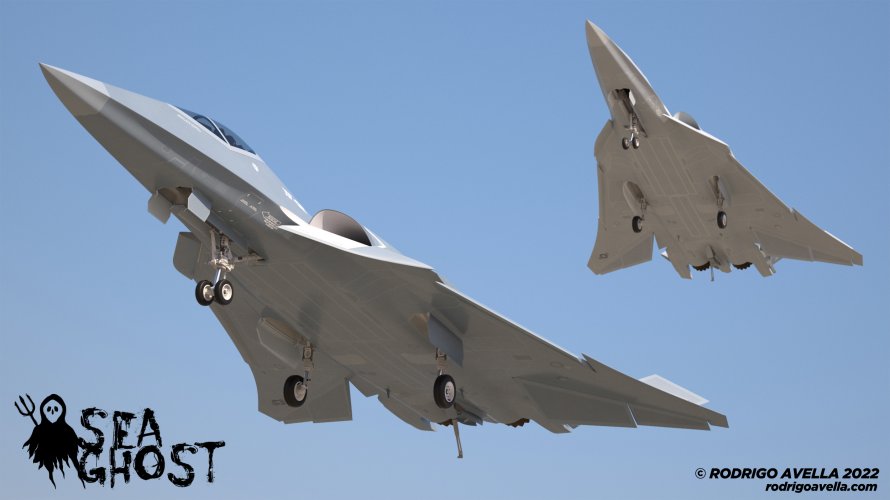
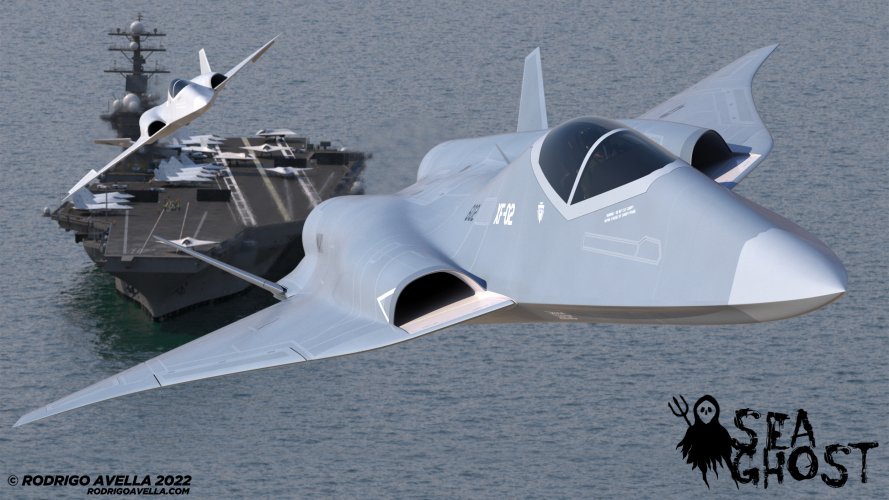
Alright. This is probably the most optimal solution I could come up with.

Length: 19.3m
Volume: 84m3
MTOW: 96,000 lbs
Thrust: 40k lb

Guaranteed Loadout:
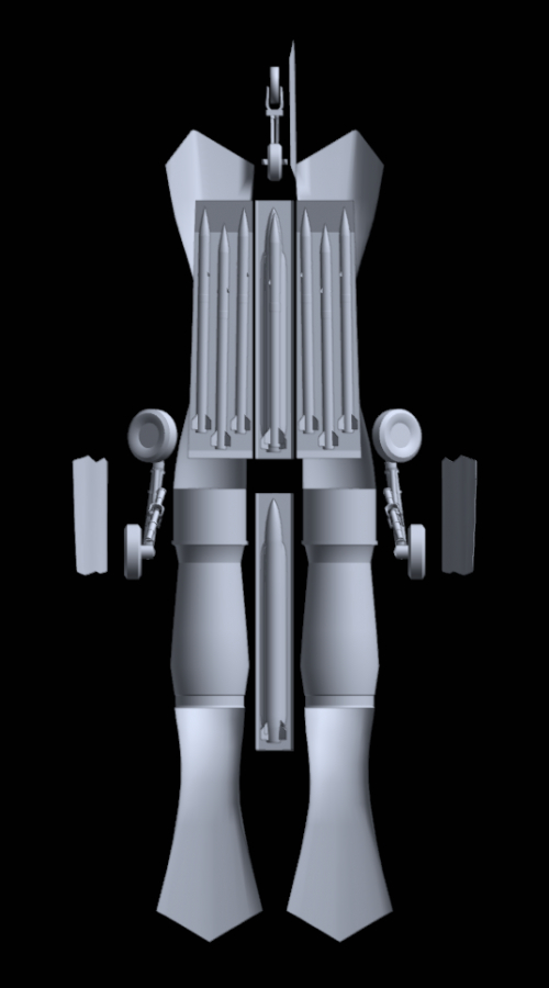
- 6x AIM120 sized AAMs
Optional Loadout:
- 2x LRAAMs Or 2x SiAW/AARGM-ER (widened the strakes too)
- The sides still have enough room to shove an additional sidewinder on each side, but I didn't model it for fear that I've already gone overboard with weapons.

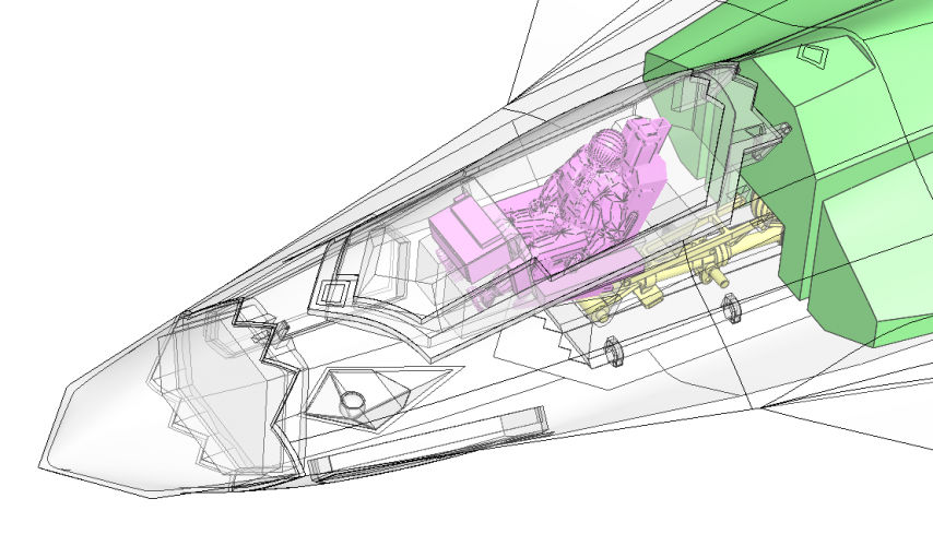
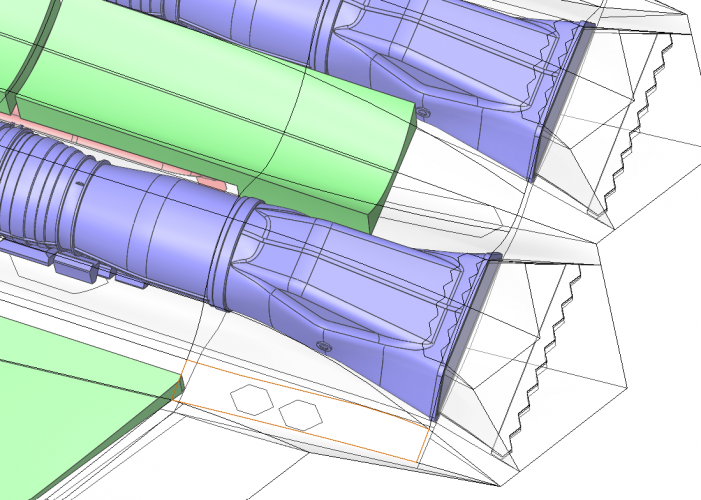
The engine is 51 inches diameter (48 inches + 3 more). The fuselage is thicker than the YF-23 and should afford enough space for engine related parts above and below it.

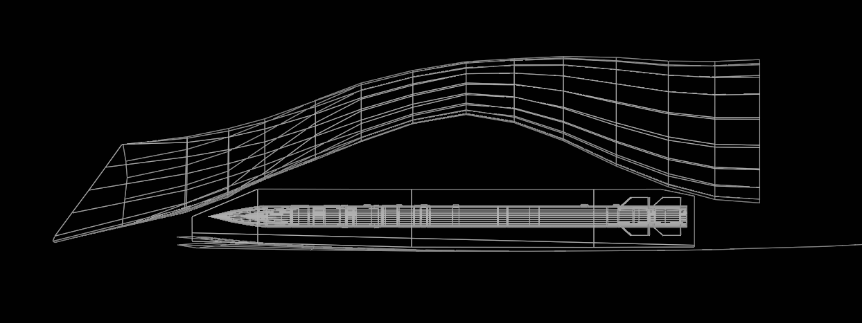
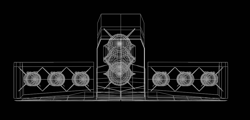
The weapon bays are modeled only as an estimation of the empty area. There's quite a bit of room between the intakes and the weapon bays for whatever bloat goes there. The aft weapon bay can be stricken from the model if it absolutely needs to fit a bunch of other engine related stuff, but there should still be enough room above it to mount engine related things. The central weapon bays are quite a bit deeper than the flatter AAM bays. The weapon bay doors open the same way the F-22 doors open. There's no space for an additional door hinge for the center bay and it doesn't seem worth it to sacrifice two AAMs to have an individually opening center bay.

Weapon bay views. This is the side view only of the AMRAAM bays. The bay has a depth of 1.6ft.
1765963625164.png
1765963745432.png

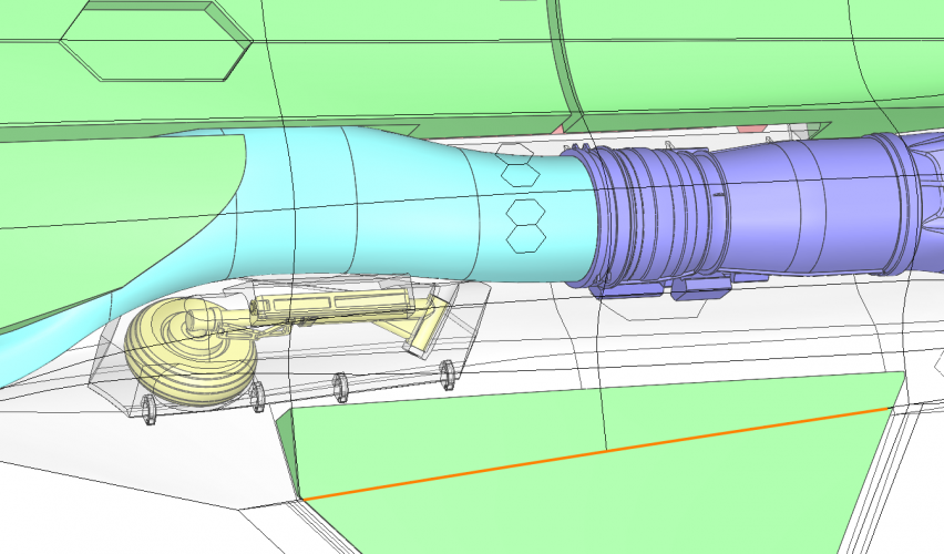
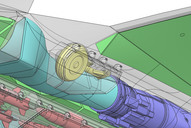
The wheels have a similar 4 - 5 inch gap with the intakes / engine walls, and even as they are still a little tight inside the wheel bays, the wheel bay could probably be expanded a tiny bit more.

Volume wise, I think I could compress it further down to sub 80m3, but everything would have to be much much tighter and I think I'm running on fumes at this point. The hardest thing to work into is actually the stupid wheels but the easy solution here is to just expand the wing root fairing and call it a day.


1765958017010.png 1765958296384.png
It is 2:30 AM in the US of A. Gonna go take a good long nap now... hopefully I can finish this up and send it out and move on to something that doesn't require me spending 4 days to figure out how to shove a wheel into an airframe :D
 
Last edited:
Alright. This is probably the most optimal solution I could come up with.

Length: 19.3m
Volume: 84m3
MTOW: 96,000 lbs
Thrust: 40k lb
Great work!
It is 2:30 AM in the US of A. Gonna go take a good long nap now... hopefully I can finish this up and send it out and move on to something that doesn't require me spending 4 days to figure out how to shove a wheel into an airframe :D
I feel you :D
 
I also modified my model slightly to give the engines more space. This increased the volume to 78.87 m³...

Model 432 specs:
Length: 19.5 m
Wingspan: 14.0 m
Volume: 79 m³
MTOW: 90566 lb (41080 kg) ... Same density as @Reddington777 used (520 kg/m³)
Thrust: 2x 40000 lb

F-22 specs, for comparison:
Length: 18.92 m
Wingspan: 13.56 m
Volume: unknown
MTOW: 83500 lb (37875 kg)
Thrust: 2x 35000 lb

Edit: In addition, Su-57 specs:
Length: 20.1 m
Wingspan: 14.1 m
Volume: unknown
MTOW: 77162 lb (35,000 kg)
Thrust: 2x 32,000 lb


NGDA_Airframe_432_052.png
 
Last edited:
Alright. This is probably the most optimal solution I could come up with.

Length: 19.3m
Volume: 84m3
MTOW: 96,000 lbs
Thrust: 40k lb

Guaranteed Loadout:
- 6x AIM120 sized AAMs
Optional Loadout:
- 2x LRAAMs Or 2x SiAW/AARGM-ER (widened the strakes too)
- The sides still have enough room to shove an additional sidewinder on each side, but I didn't model it for fear that I've already gone overboard with weapons.
I'm really digging it, I think this is really close to what the beast is currently looking like.

And I'm torn about the Sidewinder bays.
On the one hand, they are overkill. What on earth is going to get close enough to this thing to need a Sidewinder to tell it to piss off?
On the other hand, that real estate could be useful for radar arrays.
And on the gripping hand, it is really useful to have a side bay for a HalfRAAM etc to maintain your stealth while still able to send a missile at someone.


Volume wise, I think I could compress it further down to sub 80m3, but everything would have to be much much tighter and I think I'm running on fumes at this point. The hardest thing to work into is actually the stupid wheels but the easy solution here is to just expand the wing root fairing and call it a day.
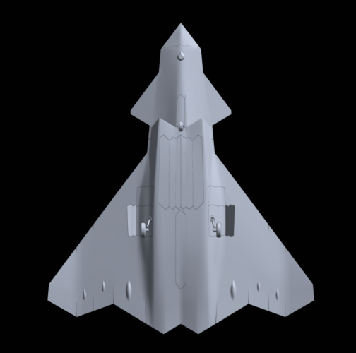
No, I think this is about the right size. 80-90m3 feels like a better size than sub-80.
 
On the other hand, that real estate could be useful for radar arrays.
Yes. This and DEW. I'm not familiar with radar arrays, but would cheek arrays and DEW weapons fit where the sidewinder bays would of been?
And on the gripping hand, it is really useful to have a side bay for a HalfRAAM etc to maintain your stealth while still able to send a missile at someone.
Could be useful for the sheer number of UAVs roaming around.
 
Last edited:
i just wonder
since Boeing merge with McDonnell-Douglas
Could F-47 based on JAST 7 concept by McD-D ?
JAST 7 looks remarkably similar to what I arrived at, so if I turn out to be right then the lineage is clear.

Maybe LM should look back at the JAST studies again to see what an upgraded F-35 could look like too.
 
Last edited by a moderator:
Quite right NightmareMoon3. I do not like what it looks like one bit if that is indeed what the finished F-47 IS going to look like.
 
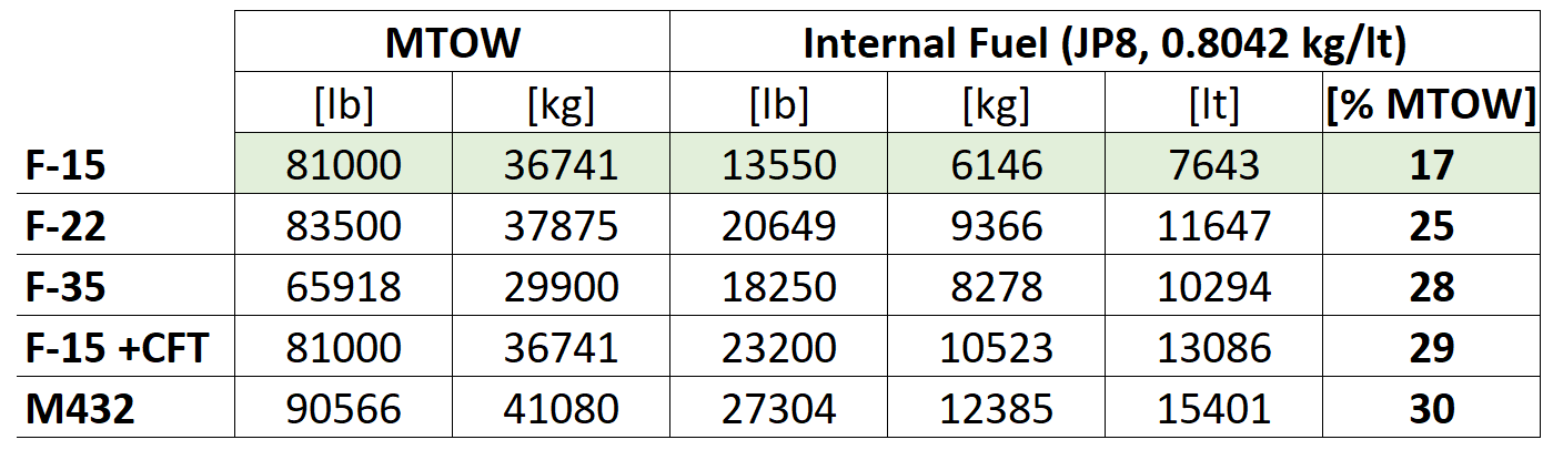
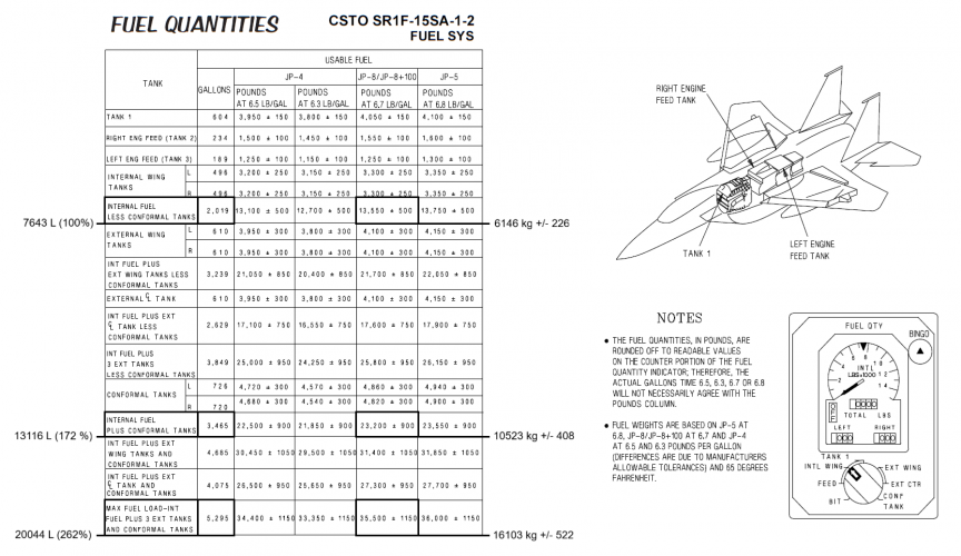
To estimate the fuel capacity of the Model 432, I integrated fuel tanks. For modeling the tanks, I used a copy of the solid model, cut it into the desired pieces and shrinked them. … Total volume: 15401 liters

For comparison:*

M432_FuelQuantities_003.png
*The F-15's internal fuel specs are taken from the flight manual and served as the basis for calculating the values for the other aircraft.
 

Attachments

  • Flight Manual_F-15SA_Fuel_002.png
    Flight Manual_F-15SA_Fuel_002.png
    397.8 KB · Views: 205
  • M432_FuelQuantities_002.PNG
    M432_FuelQuantities_002.PNG
    1.1 MB · Views: 231
  • M432_FuelQuantities_001.PNG
    M432_FuelQuantities_001.PNG
    961.8 KB · Views: 241
Last edited:
To estimate the fuel capacity of the Model 432, I integrated fuel tanks. For modeling the tanks, I used a copy of the solid model, cut it into the desired pieces and shrinked them. … Total volume: 15401 liters

For comparison:*

View attachment 795900
*The F-15's internal fuel specs are taken from the flight manual and served as the basis for calculating the values for the other aircraft.
So when do we get this on MSFS?
 
To estimate the fuel capacity of the Model 432, I integrated fuel tanks. For modeling the tanks, I used a copy of the solid model, cut it into the desired pieces and shrinked them. … Total volume: 15401 liters

For comparison:*

View attachment 795900
*The F-15's internal fuel specs are taken from the flight manual and served as the basis for calculating the values for the other aircraft.
What tolerances / clearances did you use for fuel tanks?
 
What tolerances / clearances did you use for fuel tanks?

Of course, it's important to remember that this is just a conceptual design and does not represent a real aircraft with an internal structure.

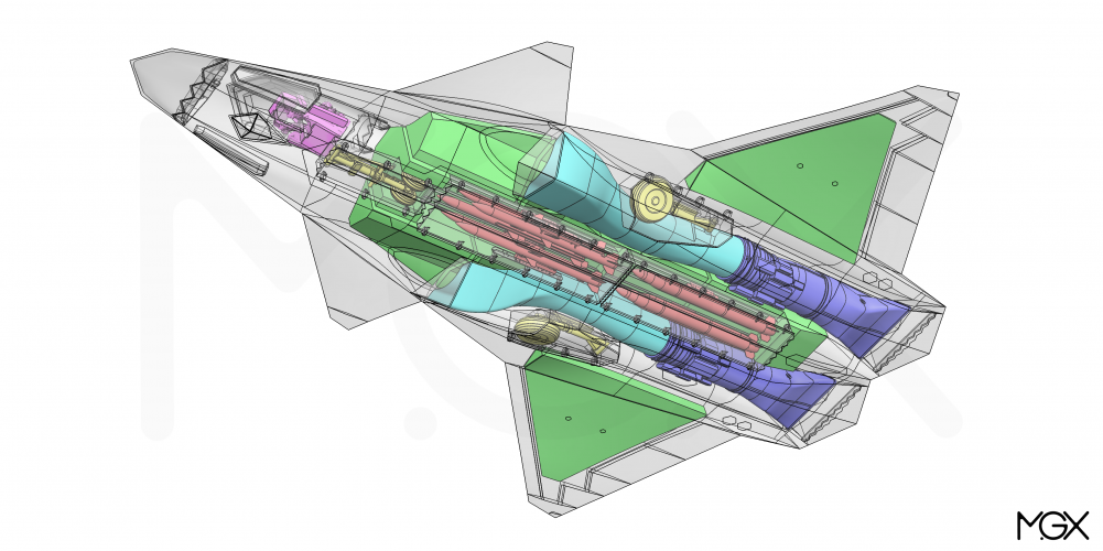
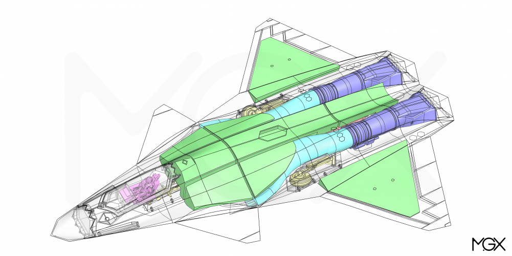
To keep the tanks from becoming unrealistically large I left some space in certain areas. For example, the space in front of the engines, which surrounds the intake ducts, is completely clear. I also left plenty of space to the left and right of the engines, towards the wings. Likewise, there is plenty of space around the main landing gear bays and at the bottom of the ducts.
Screenshot 2025-12-21 175620.png Screenshot 2025-12-21 175726.png

Furthermore, I have accounted sufficient space for various equipment, in the front and rear section of the fuselage.
Screenshot 2025-12-21 181533.png Screenshot 2025-12-21 181824.png

Where the tanks touch the outer skin, I maintained a gap of approximately 2 inch (wings 1 inch). Internally, for example, where the tanks touch the weapons bays, the gap is only about 0.5 inches. I also cut the entire centre body into seven parts, each 4 inches apart.

It is an estimate, but I think the accuracy is within reasonable margin.

Btw, the tanks occupy 19.5% of the aircraft's total volume.
 
Last edited:
To estimate the fuel capacity of the Model 432, I integrated fuel tanks. For modeling the tanks, I used a copy of the solid model, cut it into the desired pieces and shrinked them. … Total volume: 15401 liters

For comparison:*

View attachment 795900
*The F-15's internal fuel specs are taken from the flight manual and served as the basis for calculating the values for the other aircraft.
That does check with what I was guesstimating for my FAXX, though I was assuming a lighter mission takeoff weight (no externals)
 
That does check with what I was guesstimating for my FAXX, though I was assuming a lighter mission takeoff weight (no externals)
The chart shows maximum takeoff weight (MTOW).

Btw, it's remarkable that the F-35 has roughly the same percentage of fuel as the F-15 with CFTs, but obviously the F-15 doesn't have a weapons bay.
 
Last edited:
I've been contemplating two different F/A-XXs: one nearly subsonic, similar in performance to the hornet, and another leaner but more kinematically capable.

Below is a mock up based on NG's ESAV model, their ATA proposals and their apparently irrevocable love for cranked kites (plus some early F/A-XX drawings found in PPTs).

For dorsal intakes, would it be possible to have split ducting as follows:

1. The always open dorsal inlet constantly stays open.
2. A ventral inlet that remains closed typically but at high AoA, it could open up to consume air from the bottom
3. A lower forward fuselage that always pushes air over the ventral inlet mouth and the inlet mouth when closed is a flush bump along the fuselage, incurring a drag penalty but allowing ingestion of ventral air when dorsal intakes don't have enough air.

Not sure if already done or not. If someone did this already then that's great news. It could also just be completely infeasible.

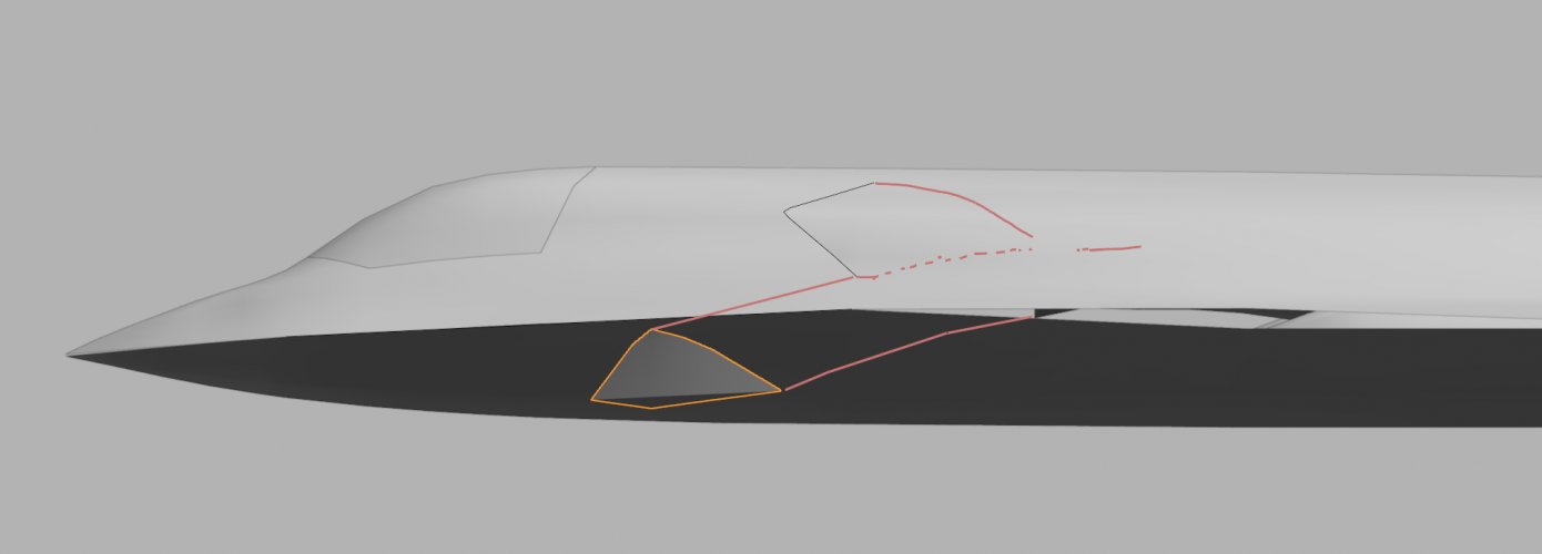
Below the red outlines the ducting. The dotted red line is some kind of paneling or door that opens up the top inlet or the bottom inlet. If inlet length is problematic, I could certainly have the two intakes just right on top of each other and aligned. I'll just have to move / remove the two LRASMs
1766431165443.png

Deployed:
The bottom inlet can be thought of as a lever wrapped in flexible material, that pops out from the fuselage when deployed, and becomes flush with the fuselage when stowed.
1766431298619.png
Stowed:

The bottom forward fuselage doesn't travel with the chine but is somewhat narrower and gradually pushes air over the stowed ventral intake. When needed, the ventral intake opens into the airstream and ingests air to support the dorsal intake.
1766431321841.png
1766432315617.png
Is this a thing? or even workable at all?
 

Attachments

  • 1766431201630.png
    1766431201630.png
    89.5 KB · Views: 155
Last edited:
screenshot_20251210_002800_chrome-jpg.795741

thanks @GRM
i have to clean my screen and keyboard from Vomit...
 
For dorsal intakes, would it be possible to have split ducting as follows:

1. The always open dorsal inlet constantly stays open.
2. A ventral inlet that remains closed typically but at high AoA, it could open up to consume air from the bottom
3. A lower forward fuselage that always pushes air over the ventral inlet mouth and the inlet mouth when closed is a flush bump along the fuselage, incurring a drag penalty but allowing ingestion of ventral air when dorsal intakes don't have enough air.

Is this a thing? or even workable at all?

I think that, in general, split intake ducting should be avoided whenever possible. It should only be considered if a simpler solution isn't applicable, or it offers significant advantages. Otherwise it only adds weight, drag and complexity.
 
I think that, in general, split intake ducting should be avoided whenever possible. It should only be considered if a simpler solution isn't applicable, or it offers significant advantages. Otherwise it only adds weight, drag and complexity.
Does the split intake itself create more drag? or just the shaping to accommodate it?

I can kind of understand the cause - when the plane's body is angled enough, intakes sitting atop the plane would have it's airflow interrupted by the plane's own body and won't be able to ingest enough air, but how much AoA would cause this isn't clear to me. Northrop's ATA proposal also had dorsal intakes so perhaps for a strike only fighter, the AoA requirements aren't as high and there's no need to build complicated ducting to acommodate it.

For a more kinematically capable fighter, the natural answer might be using levcons - if I understood the root of the problem correctly.
 
Does the split intake itself create more drag? or just the shaping to accommodate it?
I meant that in general terms. Splitting the duct increases the wetted area (drag).
I can kind of understand the cause - when the plane's body is angled enough, intakes sitting atop the plane would have it's airflow interrupted by the plane's own body and won't be able to ingest enough air, but how much AoA would cause this isn't clear to me. Northrop's ATA proposal also had dorsal intakes so perhaps for a strike only fighter, the AoA requirements aren't as high and there's no need to build complicated ducting to acommodate it.
There was a lengthy discussion about dorsal intake in this thread...
https://www.secretprojects.co.uk/th...eight-multirole-fighter-lmf.38539/post-508131

I also came up with some ideas how to implement a dorsal intake on a stealth fighter..
https://www.secretprojects.co.uk/th...eight-multirole-fighter-lmf.38539/post-576929
and how to improve high AoA performance...
https://www.secretprojects.co.uk/th...eight-multirole-fighter-lmf.38539/post-625374

For a more kinematically capable fighter, the natural answer might be using levcons - if I understood the root of the problem correctly.
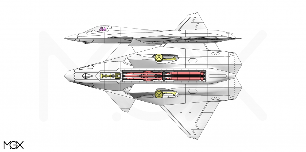
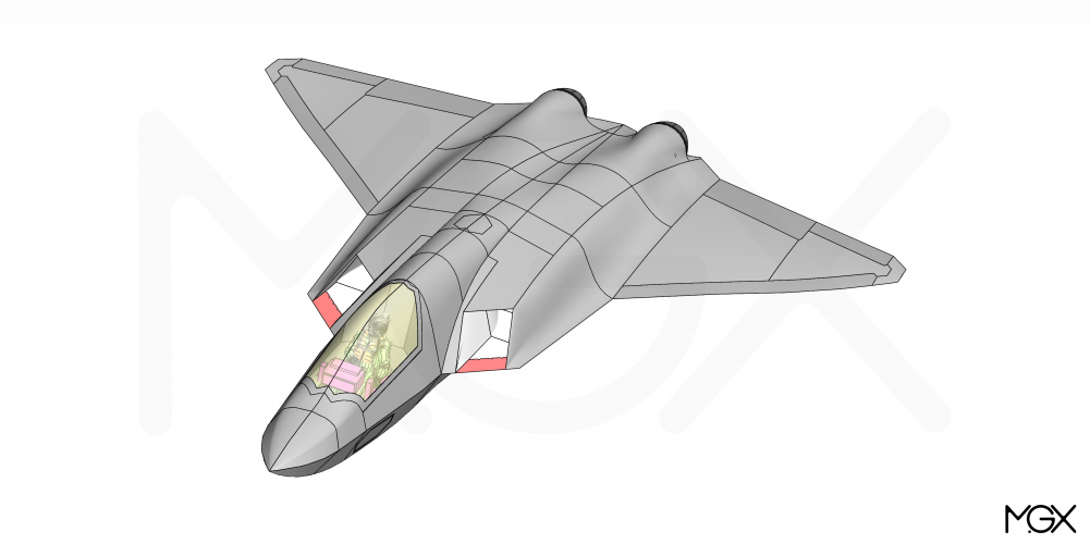
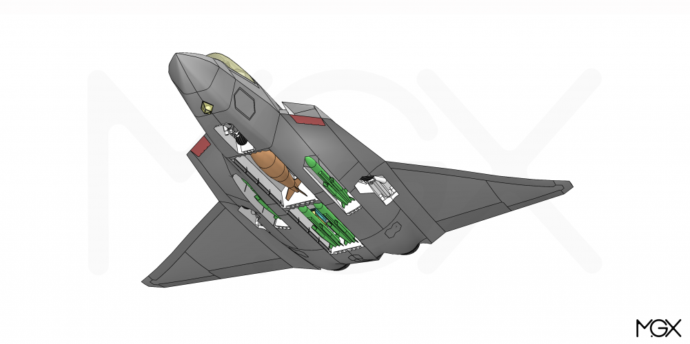
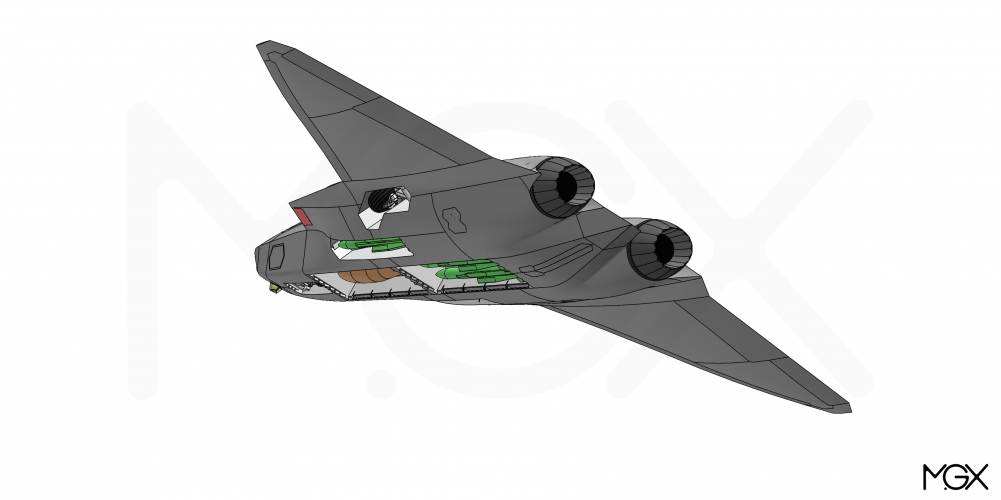
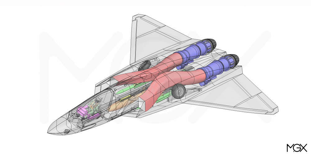
LEVCONs may work well for dorsal intakes. I designed something along those lines at some point. Those are not really LEVCONs, rather movable lower intake lips, like those found on the EF Typhoon (marked red). This should improve high AoA performance and the dorsal intake arrangement keeps the underside clear, which allows for more flexibility in the placement of the bays for weapons and landing gears...

This model was intended as a European answer to the F-35, powered by two engines with 3D thrust vectoring, in the size of the F414/EJ200 :)
 

Attachments

  • MGX_MMF_001.PNG
    MGX_MMF_001.PNG
    586.6 KB · Views: 230
  • MGX_MMF_002.PNG
    MGX_MMF_002.PNG
    631.3 KB · Views: 209
  • MGX_MMF_004.PNG
    MGX_MMF_004.PNG
    422.3 KB · Views: 204
  • MGX_MMF_003.PNG
    MGX_MMF_003.PNG
    882.1 KB · Views: 196
Last edited:
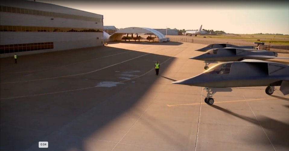
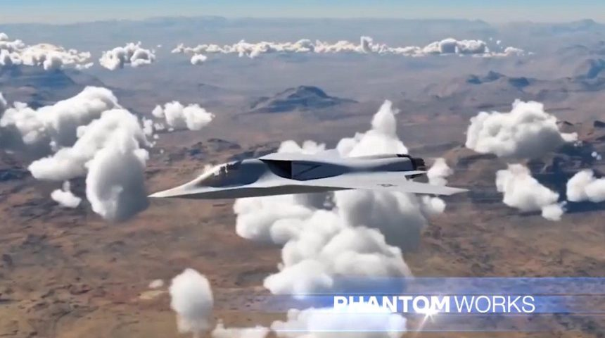
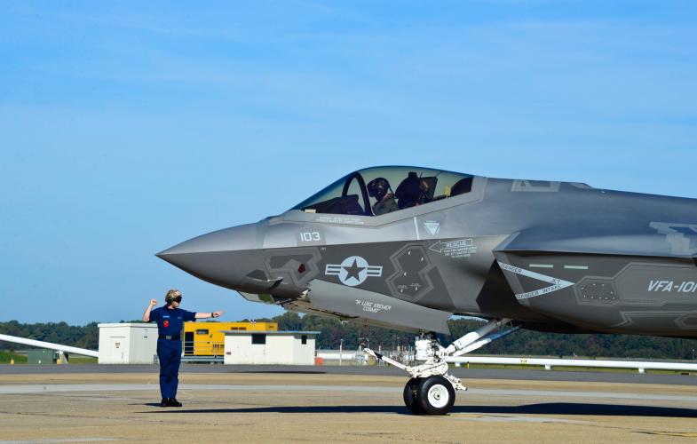
There is a great debacle back and forth over a common service platform. But this is being shown in the F-47 page and that render has a launch bar and last I checked the airforce doesn't have danger marks for their intake. Outside of that one, as common as it has been displayed, the last non-navalized 6th gen fighter that Boeing displayed was the one with the converting tail plane.
 
I meant that in general terms. Splitting the duct increases the wetted area (drag).

There was a lengthy discussion about dorsal intake in this thread...
https://www.secretprojects.co.uk/th...eight-multirole-fighter-lmf.38539/post-508131

I also came up with some ideas how to implement a dorsal intake on a stealth fighter..
https://www.secretprojects.co.uk/th...eight-multirole-fighter-lmf.38539/post-576929
and how to improve high AoA performance...
https://www.secretprojects.co.uk/th...eight-multirole-fighter-lmf.38539/post-625374


LEVCONs may work well for dorsal intakes. I designed something along those lines at some point. Those are not really LEVCONs, rather movable lower intake lips, like those found on the EF Typhoon (marked red). This should improve high AoA performance and the dorsal intake arrangement keeps the underside clear, which allows for more flexibility in the placement of the bays for weapons and landing gears...

This model was intended as a European answer to the F-35, powered by two engines with 3D thrust vectoring, in the size of the F414/EJ200 :)
Hi! What a beautiful design. Congratulations.
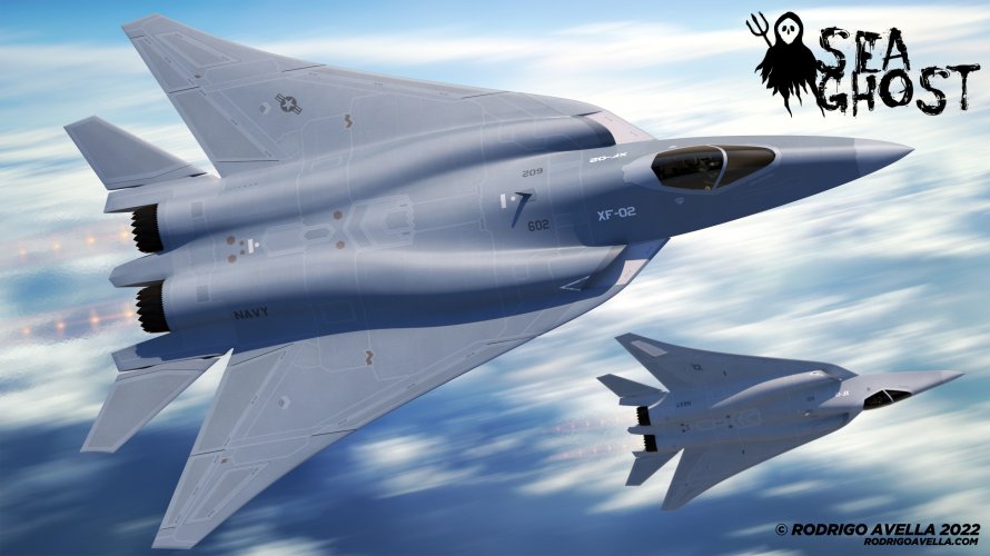
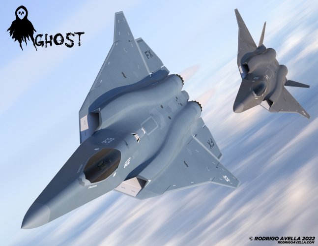
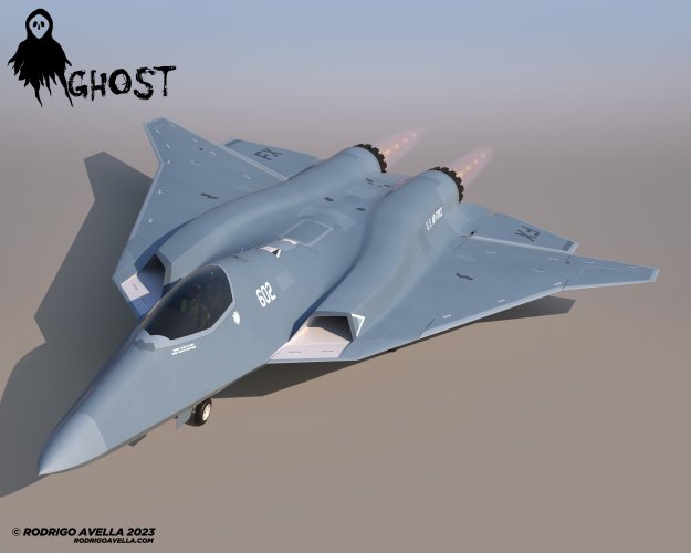
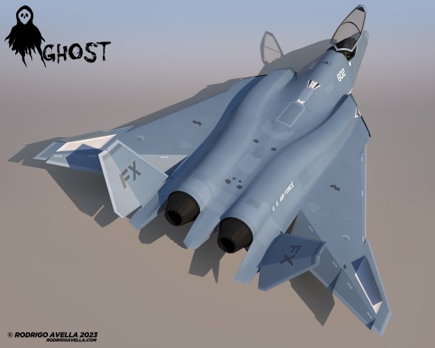
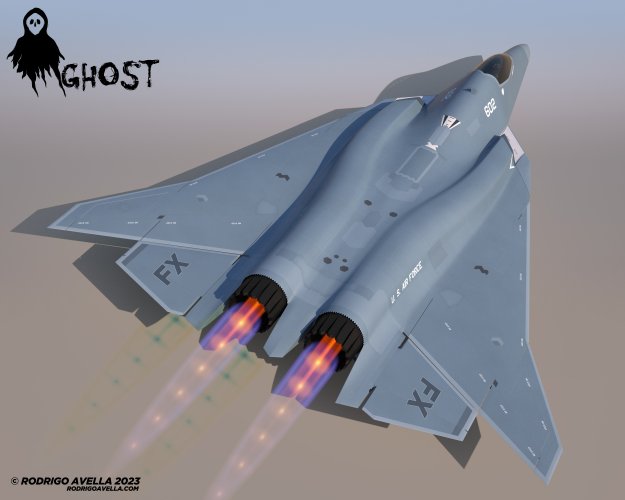
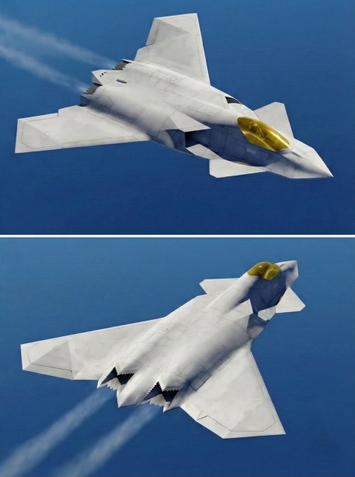
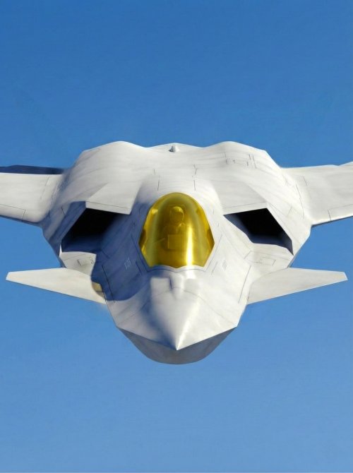
A few years ago, I tried something similar for an FX and FA-XX concept:
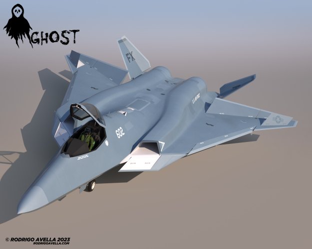
You can see it in the FA-XX video and in some images.
I never did a fluid dynamics simulation to see how it would work.


03.jpg

05.jpg

08.jpg
02.jpg
13.jpg
01.jpg
05.jpg

06.jpg 07.jpg 08.jpg
 

Similar threads

Back
Top Bottom