Oblique Flying Wing ?

Steve Morris’ 20 ft OFW (first flight 1994). It was designed to fly at sweep angles between 35° and 68° and a maximum speed of about 65 mph. (Photo courtesy of the Hiller Aviation Museum).
The oblique flying wing small-scale demonstrator
aircraft was built to study handling qualities,
investigate computer control algorithms for stability
augmentation, and to demonstrate the feasibility of
the inherently unstable configuration. The model's
configuration matches the design developed by
researchers at NASA Ames Research center for
use as a 400 passenger SST that would fly from Los
Angeles to Tokyo at Mach 1.6, but have the same
ticket price as a 747. The full-size aircraft has a 400
ft. span and all 400 passengers sit inside the center
portion of the wing (figure 1). The sweep angle
varies in flight from 35" at take-off to 68" at cruise
for reduced supersonic wave drag. The airplane is
unstable in pitch so that efficient airfoil shapes can
be used and so that the internal volume of the wing
can be efficiently filled with passengers.
The model (figure 2) has a 20 ft. wingspan and
weighs 80 lbs.
source:
Flight tests of an oblique flying wing small scale demonstrator
AIAA-1995-3327
AIAA Guidance, Navigation and Control Conference, Baltimore, MD, Aug 7-10, 1995, Technical Papers. Pt. 3 (A95-39609 10-63), Washington, DC, American Institute of Aeronautics and Astronautics, 1995, p. 1416-1425


Morris OFW Flight Testing
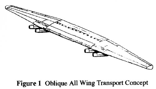
During the above studies, NASA Ames funded Steve
Morris at Stanford University to build and fly two smallscale
OFW aircraft; these were the first powered oblique
flying wing flight demonstrations. NASA’s grant allowed
Morris to develop these demonstrators in order to study
handling qualities, investigate control algorithms for stability
augmentation, and demonstrate the feasibility of the
inherently unstable configuration and its applicability to the
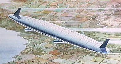
full-scale OAW transport discussed above (specifically to
emulate the 1991 design depicted in Figure 43). In support of
the F-8 OWRA program, Morris had previously analyzed the
lateral accelerations of the AD-1 simulation results and found
a way to simultaneously optimize the aerodynamic
configuration and the handling qualities of oblique wing
aircraft. Morris research in support of his thesis addressed
issues discovered during the OWRA program including
aeroelastics, stability and control, and aerodynamic issues of
oblique wing aircraft.75
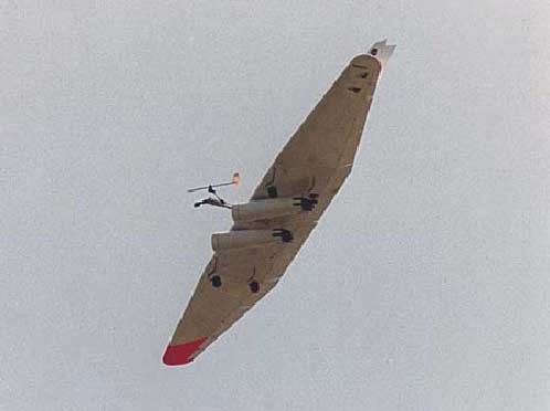
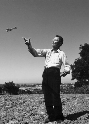
The first model (Figure 48) was a 10 ft span radio
controlled aircraft powered by a single propeller, capable of
pivoting to effect the vehicle sweep angle between 25° and
65°. Aircraft characteristics are given in Table 14. The
model was statically stable in pitch and had no flight
computer for stability augmentation, being manually
controlled using radio control.*
For control, the aircraft used three trailing edge surfaces
and a single all-moving vertical fin. It crashed on its first
flight due to pitch effects of the single large vertical tail: the
aerodynamic load centroid of the fin was too far
above the plane of the wing, producing a significant
pitching moment that overpowered the pitch
authority of the flaps. A vortex lattice code was
used to model this and to explore ways of correcting
this phenomenon. Morris’ studies showed that if the
fin was canted, the aerodynamic force vector from
the fin could go through the pitch axis, decoupling
the force. Many vertical tail configurations were
tested with a final result of using two smaller fins.
The model was flown extensively over a 6 month
period, as shown in Figure 49, eventually flying up
to sweep angles of 65° briefly to verify that there
was adequate control authority to trim the aircraft at
this flight condition. During several of the flights,
Morris attached long streamers to the trailing edge
to see the sweep angle in flight. 75-77, *
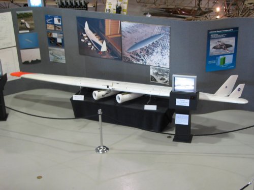
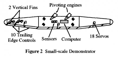
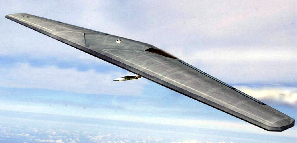
The second aircraft had a 20 ft (unswept) span
and used 10 trailing edge control surfaces, as well
as two all-moving vertical fins. The aircraft was sized to be a 5%-scale model of the full-scale 400 passenger OAW
(Figure 43). Trailing edge surfaces were sized to be 25% of the local wing chord in order to produce the most
control authority within a reasonable size. The vertical fins were sized for sufficient control authority in the event of
an engine failure, but the centroid of the loading was kept close to the surface of the wing in order to avoid pitch
coupling.
The second aircraft weighed 80 lb and was powered by two radio control model aircraft 5 hp single cylinder
engines driving ducted fans that produced 12.3 lb of thrust at 23,000 rpm; the fans could pivot to effect the variable
sweep in flight from 35° to 68°. The 48 oz of fuel was sufficient for about 6 minutes of flight time. The landing gear
was a fixed, quadracycle gear arrangement with four wheel steering to allow the aircraft to taxi. The model used
three flight sensors: a 3-axis rate gyro, an angle of attack, and angle of sideslip vane, and a wind turbine air speed
indicator. Figure 50 shows a general comparison of the two aircraft.
The airframe was constructed of an aluminum spar with steel sub-spars to support the landing gear, engines and
fins. Wing ribs covered by Kevlar and foam molded skin formed the aircraft surface. The leading edges were formed
from balsa and fiberglass; the entire trailing edge was comprised of the balsa control surfaces, which were sized by
the maximum torque that the servos could produce.
Prior to flight, the model was evaluated in a
captured “flight” affixed on a universal three-degree of
freedom pivot on top of an automobile. The vehicle
was driven at the full range of flight speeds, exposing
the aircraft to a realistic environment with
aerodynamic forces and moments approximately
equivalent to those in flight. This testing was used to
verify the desired function of the stability
augmentation system, control surface authority, and
trim settings prior to first flight. Ten series of tests
were conducted at Moffett Field/Ames Research
Center, providing a thorough investigation of the
aircraft’s aerodynamic behavior and its stability
augmentation system with a variety of control gain
settings.
The model was 1.5-1.7% statically unstable in
pitch. Initially, it was intended to be 7% unstable (to
match the proposed operational vehicle), but during
the vehicle testing, the off-the-shelf servos were
determined to be too slow to control the vehicle
adequately. In addition, vehicle testing also
showed that the ducted fans created a pitching
moment, because their thrust line passed below
the aircraft center of gravity. It had been hoped
that the resulting induced flow over the control
surfaces would increase their effectiveness
sufficiently that a small flap deflection would
correct this moment. Vehicle tests, however,
showed that at full power, the thrust-dependent
pitching moment was too great to be trimmed by
a flap deflection. As a result, deflecting vanes
were placed in the fan efflux, reorienting their
thrust through the center of gravity. Once these
were installed, the vehicle tests proved that there
was no change in pitch trim with throttle changes.
The final series of vehicle-mounted “flights”
were conducted to verify the stability and trim
settings. The controls were set so that the aircraft
would have no rolling moment at the lift-off
conditions of 10° angle of attack and 35° sweep,
in order to minimize the danger of losing the
aircraft during take-off.
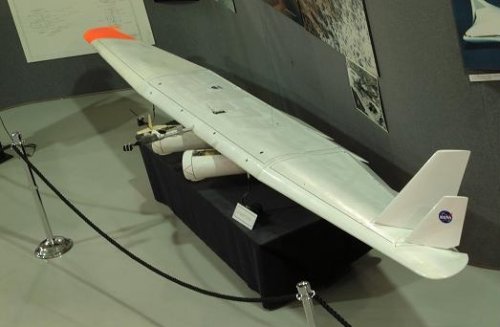
The 20 ft model performed a single flight in
May 1994 at Moffett Field, adjacent to NASA
Ames (Figures 51 and 52). During a 23 second
take-off roll, the aircraft accelerated to 45 mph
and then rotated for lift off. It flew to an altitude
of 150 ft and made a left hand turn around the
airfield. The model was flown at speeds from 25
to 65 mph (at 35° sweep). During the second
circuit, the wing sweep was momentarily
increased to 50°. At the end of this pass, the
model was landed to ensure it didn’t run out of
fuel. Total flight time for this flight was only 4
minutes. Budget constraints precluded additional
flight testing.
NASA had hoped to follow the supersonic
wind tunnel tests and Morris’ small OFW tests
with a 1/10th-scale supersonic unmanned
demonstrator, but sufficient interest and funding
did not materialize.
source (one of the authors is forum member Mike Hirschberg aka vstol)
A Summary of a Half-Century of Oblique Wing Research
Michael Hirschberg CENTRA Technology, Inc., Arlington, VA, UNITED STATES; David Hart CENTRA Technology, Inc., Arlington, VA, UNITED STATES; Thomas Beutner DARPA, Arlington, VA, UNITED STATES
AIAA-2007-150
45th AIAA Aerospace Sciences Meeting and Exhibit, Reno, Nevada, Jan. 8-11, 2007
 

Attachments

  • nasa ames ofw.jpg
    nasa ames ofw.jpg
    56.1 KB · Views: 410
  • Morris 2nd OFW model.jpg
    Morris 2nd OFW model.jpg
    136 KB · Views: 382
Orionblamblam said:
I believe that's the Hiller museum in California, south of San Fran.

bingo
 

Attachments

  • Hiller Museum 80ft OWF.jpg
    Hiller Museum 80ft OWF.jpg
    54.2 KB · Views: 346
Matej said:
It seems to be NASA project. NASA was relatively active in this technology as the civil counterpart to Northrop Grumman.

Yeah I did know that. I've seen another old UAV test vehicle for the OFW at the Smithsonian Institute. I can't wait to see this design exploited more in the future if it ever does get exploited. I'm no expert but it looks like a promising way to shift the aspect ratio of an a/c to optimize for efficiency in different flight regimes.
 
A 1989 airliner concept based on the same configuration:
 

Attachments

  • NASA 1989 Flying Oblique Wing.JPG
    NASA 1989 Flying Oblique Wing.JPG
    28.6 KB · Views: 122
I wonder how much of an obstacle rotating (generally podded) engines and the single large axis of the wing present when considering RCS reduction in such a configuration? Does it have VLO potential?
 
if you will take time to read link that was just above your post you will find NG OFW bomber concept that doesn't have podded engines at all - they are hidden in centerplane and fixed, feeded through all envelope by magic of complicated intake geometry
 
With the engine problem fixed according to the link posted then there doesn't appear to be any problem with an Oblique Flying Wing's RCS to my knowledge. There aren't that many control surfaces to reflect off of so that would certainly be a plus for a low observable design.
 
flateric said:
if you will take time to read link that was just above your post you will find NG OFW bomber concept that doesn't have podded engines at all - they are hidden in centerplane and fixed, feeded through all envelope by magic of complicated intake geometry

Yes - there are even pictures...

:-[

Thanks!
 
Northrop Grumman went on to explore stealthier concepts with embedded engines.
 

Attachments

  • ngc_ofw copy.jpg
    ngc_ofw copy.jpg
    224.2 KB · Views: 29
  • ofwnew.jpg
    ofwnew.jpg
    20.7 KB · Views: 28
  • ng_ofw_op.jpg
    ng_ofw_op.jpg
    179.3 KB · Views: 29
  • US2008074795_05032009_gz_en.x4-b.jpg
    US2008074795_05032009_gz_en.x4-b.jpg
    21.6 KB · Views: 30
  • 09029796.pdf
    1.2 MB · Views: 9
  • (WO.pdf
    103.3 KB · Views: 6
I'm no aerodynamicist, but I would be highly concerned about any potential of undesirable asymmetric aerodynamic side effects of such configurations. But what exactly are the potential advantages of any asymmetric configuration supposed to be in the first place anyway?
 
Last edited:
I'm no aerodynamicist, but I would be highly concerned about any potential of undesirable asymmetric aerodynamic side effects of such configurations. But what exactly are the potential advantages of any asymmetric configuration supposed to be in the first place anyway?
In the case of an oblique flying wing, the advantage of efficiency across subsonic and supersonic regimes given by variable geometry without the weight and complexity of a symmetrical swing wing (somewhat negated when you put those swivelling engine pods on it though). As you say, the aerodynamics didn't work out well - particularly with roll control.

With different asymmetric configurations, there are other advantages.
 

Attachments

  • WG2.jpg
    WG2.jpg
    84 KB · Views: 16
  • 50821562623_ab51c42712_c.jpg
    50821562623_ab51c42712_c.jpg
    80.9 KB · Views: 20
Last edited:
Northrop did explore a nuclear-powered asymmetric flying wing bomber as an alternative to Convair's NX-2. The intent was to get the crew as far away as possible from the reactor by putting them in a pod on the port wingtip while the reactor was immediately starboard of the central engine bay. No oblique mode though, just asymmetric.
 

Attachments

  • NukeWing-PortAngle-ABU.jpg
    NukeWing-PortAngle-ABU.jpg
    33.7 KB · Views: 22
  • nuke-wing-starboard.jpg
    nuke-wing-starboard.jpg
    68.3 KB · Views: 21
That’s where the B-wing came from ;)

Any oblique b-plane designs? The wing blades could scissor/X out in a symmetrical fashion at first.
 
That’s where the B-wing came from ;)

Any oblique b-plane designs? The wing blades could scissor/X out in a symmetrical fashion at first.
Neat idea but I don't think it would work. The differing wing orientations (forward higher, trailing lower on one side and the opposite on the other) and the differing aerodynamic interactions between the wings would probably create significant asymmetries in pitch and roll that would create a lot of drag to trim out. I'd guess that the aerodynamics during wing travel would be a mess also, also due to interactions between the forward and aft wings..
 
I was thinking about such a layout of fly-back boosters…the same attachment points on a rocket core could perhaps also be used as a pivot point…wheels on the engine block.

Rocket ascends “pointy end up” but comes down engine-block leading the way…looking a bit like like a radial airplane.

No violent pitch-over, no boost-back..something a bit more gentle.
 
I'm no aerodynamicist, but I would be highly concerned about any potential of undesirable asymmetric aerodynamic side effects of such configurations. But what exactly are the potential advantages of any asymmetric configuration supposed to be in the first place anyway?

See https://ntrs.nasa.gov/api/citations/19870009137/downloads/19870009137.pdf for the flying qualities of the AD-1. At sweep angles below about 45 degrees, they seem benign. Above that, they seem to get more challenging.

As for why "In 1952 Dr. R. T. Jones proved that for any flight Mach number minimum drag at a fixed lift is achieved by an elliptic wing planform with an appropriate oblique sweep angle. Since then, wind tunnel tests and numerical flow models have confirmed that the compressibility drag of oblique wing aircraft is lower than similar symmetrical sweep designs." (https://ntrs.nasa.gov/citations/19930074026)

It doesn't seem like much has been done with oblique wing studies for quite a while. I don't think it's a dead end, but I think a successful oblique-wing transport (or bizjet) would need a powerful stability augmentation system.
 
No violent pitch-over, no boost-back..something a bit more gentle.
Again, more unsubstantiated statements. Pitch over is not "violent". It is done in rarified air, much like in a vacuum. Fly back is more stressful. Lift, maneuvers and landing add side loads the vehicle requiring more structure and mass. Boost back and landing produce loads in the axial direction for which the vehicle is already designed for. Plus they can do barge landings, something flyback can't do.

Boost back allows for the minimal mass for a reusable vehicle.
 
That’s where the B-wing came from ;)

Any oblique b-plane designs? The wing blades could scissor/X out in a symmetrical fashion at first.
Messerschmitt P.1109. Never built, let alone flown.
 

Attachments

  • 0kheyraw5fq21.jpg
    0kheyraw5fq21.jpg
    23.9 KB · Views: 9
  • unnamed-1.jpg
    unnamed-1.jpg
    13.3 KB · Views: 6
  • unnamed-2.jpg
    unnamed-2.jpg
    35.2 KB · Views: 7
  • unnamed.jpg
    unnamed.jpg
    29.7 KB · Views: 17

Similar threads

Back
Top Bottom