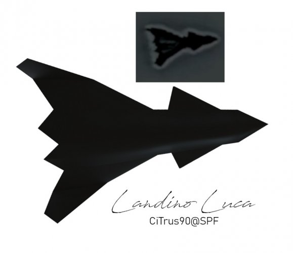
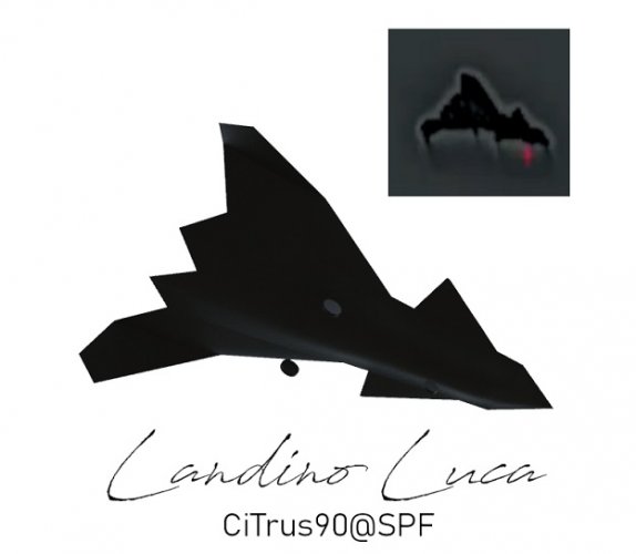
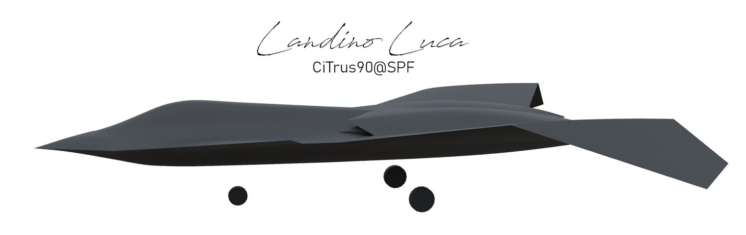
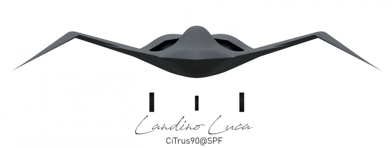
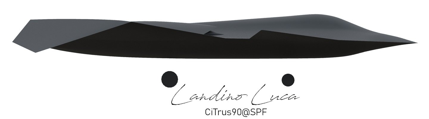
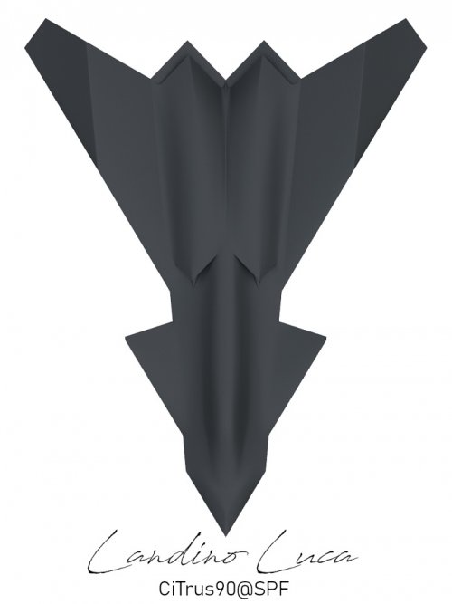
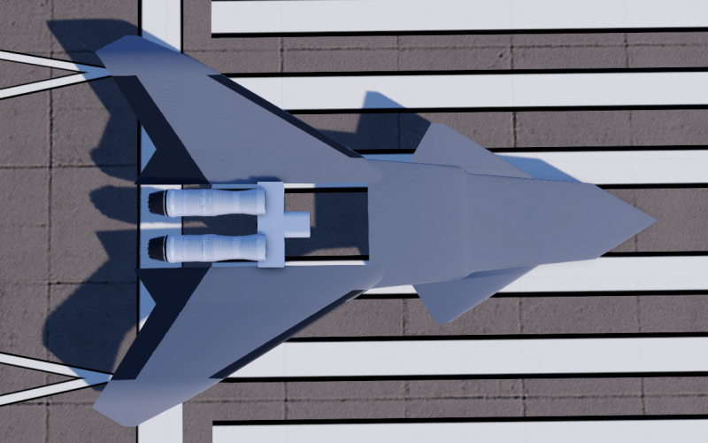
CGI - Attempted reconstruction of ProjectFear possible Boeing AII-X demonstrator

CiTrus90

Credibility is down! Kill ratio is up!
Senior Member
Joined
16 January 2015
Messages
885
Reaction score
4,846
Since I was told that the CGI - Possible configuration of the Boeing F-47 NGAD thread would not be the appropriate one for posting an attempt at visually reconstructing the aircraft shown in the ProjectFear alleged Boeing NGAD F-47 demonstrator video - June 2026 thread, I decided to start a new one.

I'll also post a few speculations of mine and will try to explain why I've taken some of the choices present in my reconstruction, so please bear with me.

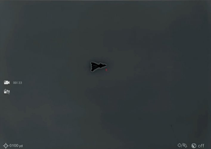
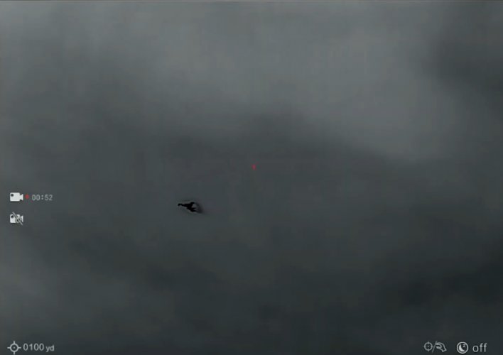
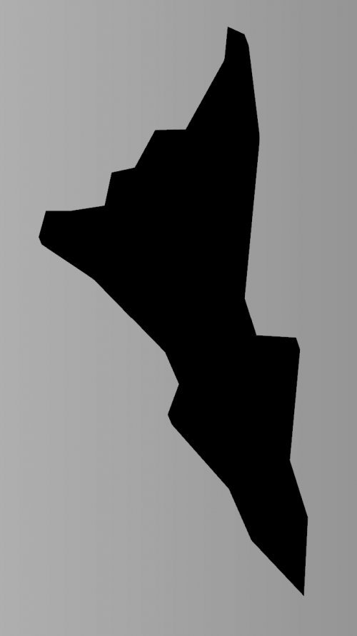
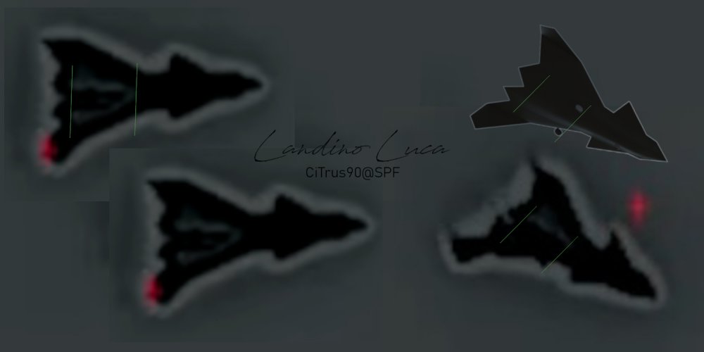
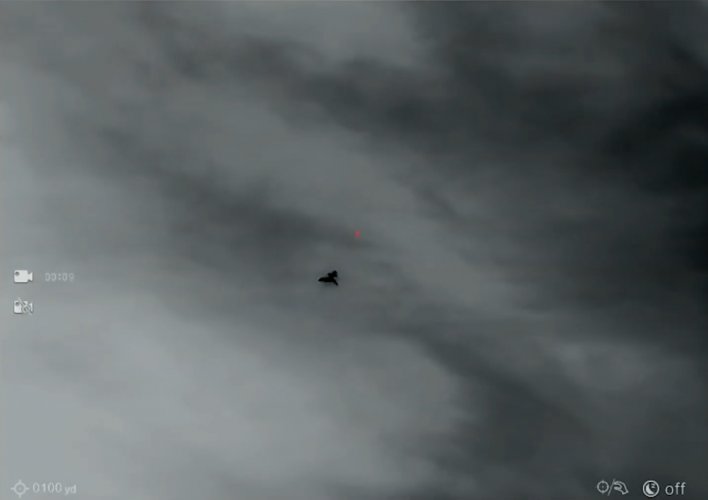
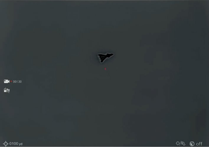
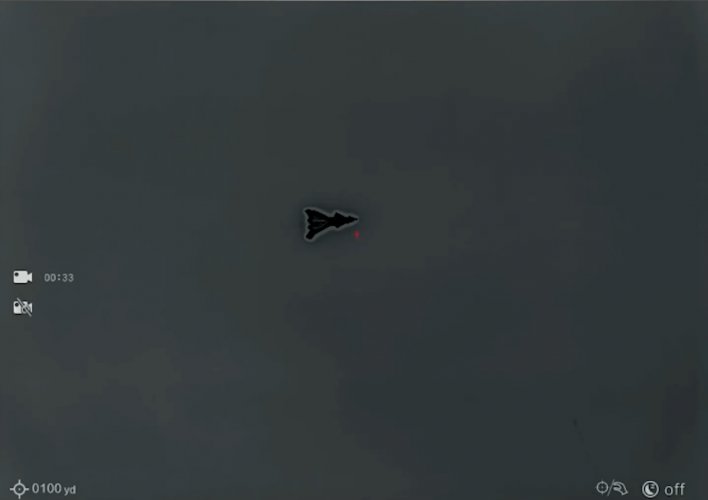
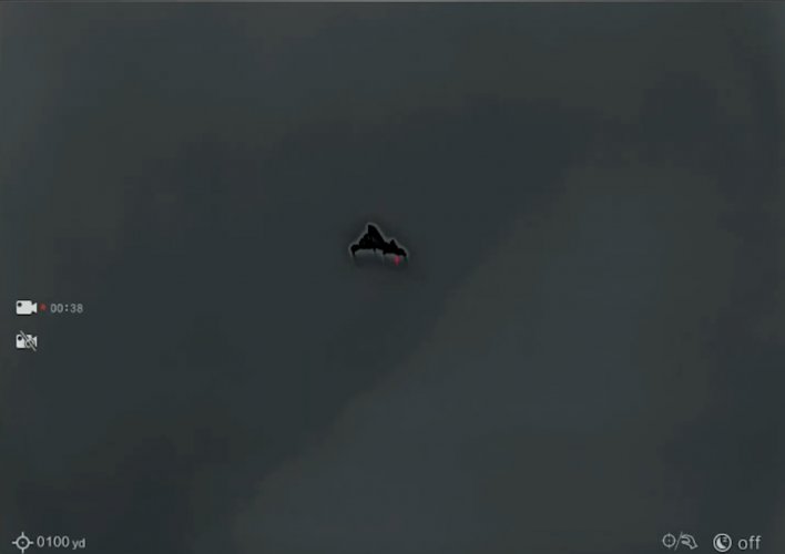
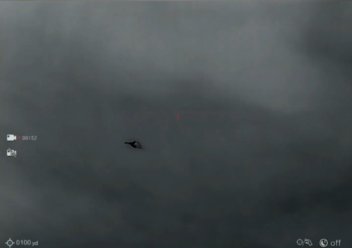
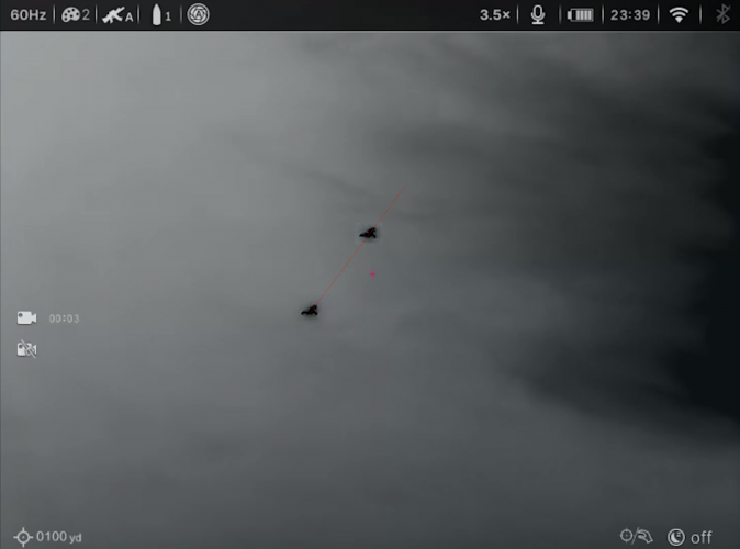
I've focused my attention on analyzing the 3 following screenshots taken from ProjectFear's youtube video, at around the 50 minutes mark:
Screenshot 3.jpg
Screenshot 4.jpg
Screenshot 6.jpg
These are the 3 frames that I believe to be the most useful for attempting a visual reconstruction of the aircraft in question.
The first picture shows the silhouette of the planform, almost perpendicular to the camera's POV. The second one shows the aircraft starting to fly away from the observers, together with the hint of a landing gear on the left side of the vehicle. The final frame shows the aircraft now getting further away from the camera, where the angles of both the main wings and canards in relation to each other are now visible and, again, a possible hint of a frontal landing gear.

As I pointed out in a previous post in another thread as well, all frames of the overflight show an area of discontinuity in coloration on the underside of the aircraft. This area is limited to a pair of symmetrical stretches at the rear of the vehicle.
My suggestion is that these differently colored areas (which appear white and are, hence, hotter than their surrounding surfaces) correspond to openings on the underside of the aircraft, compatible with landing gear bays. The heat we see is very probably seeping from the nearby engines.
Screenshot #2 is also suggestive (even more so than screenshot #3) of the presence of a lowered landing gear.

Given the length of these white stretches, that I believe to be the landing gear bays, and the position of the wheel (visible in screenshot #2), my assumption is that this aircraft is quite small.
How small precisely, I cannot say, since no marks in the background are available for reference and to conduct measurements, but it would certainly be compatible in size with the Boeing Bird of Prey or the Scaled Composites Model 401's overall dimensions.

This leads me to believe that the crew of ProjectFear was able to capture a demonstrator, which is reasonable to presume might be for the AII-X program and that, given the similarities common with the heavily redacted pictures that were released by the USAF of its F-47 program, this is a Boeing product.

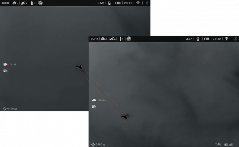
I then started to make an attempt at reconstructing its shape by trying to match in perspective the object to all 3 different screenshots at the same time.
This method has its shortcomings as, first and foremost, the available footage is far from 4K quality, so the lower resolution implies that some shapes and details will unfortunately be lost and will need to be guessed.

Perspective matching of frames #1 and #2:
Bandit - flybyA small.jpg
Bandit - gearA small.jpg

Correctly guessing the edge alignments and their relative angles is not at all an easy task, even more so when you are dealing with a 3d object where you have to take into account that some reference points might be lower or higher in relation to each other and not just more forward or backward, more left and right. So please take my reconstruction with all the necessary caution that the limitations of the available starting material impose on my even more limited abilities.

Do note from the last picture, where the landing gear is positioned: I think this reinforces my belief in the fact that this is a "small-sized" demonstrator.

And now for the full reconstruction:
Bandit - 1A small.jpg
Bandit - frontA small.jpg
Bandit - sideA small.jpg
Bandit - topA small.jpg

As you can see, I've chosen dorsal intakes for my reconstruction.
This is due to length of the gear bays that I pointed out to previously in the text above, together with the consideration of the small size of the aircraft.

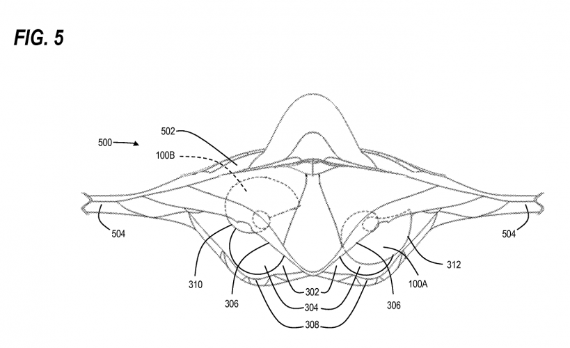
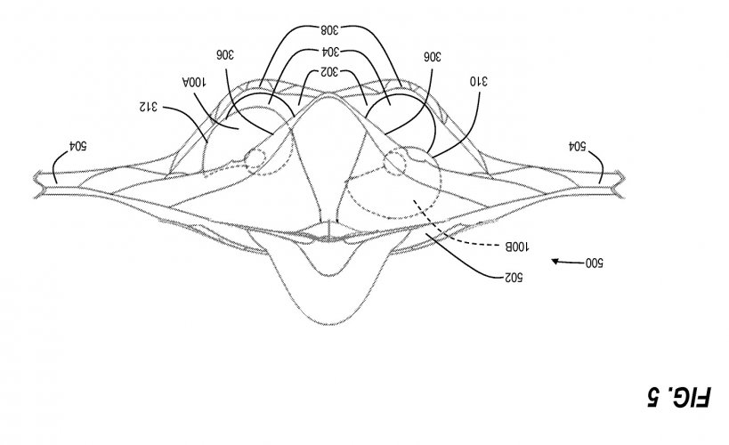
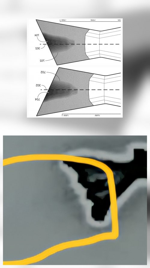
What might be considered a DSI bump in front of the intakes, is in reality an attempt at depicting a technology disclosed in a Boeing patent titled Variable-geometry rotating spiral cone engine inlet compression system and method, which shows a picture that I found of great interest:
US08690097-20140408-D00005 (1).png
Which became even more interesting once I decided to rotate the image upside down:
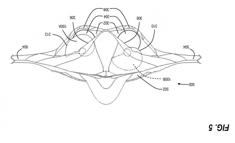
US08690097-20140408-D00005 (2).jpg

Other patents from Boeing reference some degrees of variable geometry that could apply to both the canards and the exterior part of the wings as well. I'm pointing this out because the footage, towards the end of the recording of the overflight, appears to me suggestive of some changes in planform/geometry, but the quality of the video is too poor to make a definitive judgment on this point.

That's all for now.
Constructive criticism is welcome.
Endless pages of speculation on specs and capabilities are not, so if you have any suggestions based on what you believe a demonstrator for the F-47 should be like, but that are not based on the information that can be inferred from the available footage, keep it to yourselves.
There is already enough entropy in the Universe as is, please.

Thank you.
 
How well does this match with the official F-47 renders? I still have a pet theory that these are closer to the demonstrator than the final plane.
 
There have been comments made about F-47s agility and maneuverability - if these are correct I take them as originating from Boeings AII-X planes characteristics, which seemingly clash with dorsal intakes….do you think moving them forward (potentially quite a bit) might be worth looking at?
Thank you, but as I stated in my opening post, I'm just trying to base myself on the available footage while trying to refrain from going too far with speculation.
Specs and capabilities are not something that I'm currently interested in, since we will not be able to know anything about those numbers in the foreseeable future.

All discussions about those notions risk sliding into fanboying territory and I'm sure I'm not the only one that feels exhausted by the endless speculations that have become widespread on SPF in the last years. Here, I only care about data that I can corroborate with my eyes.

I'm happy to patiently wait and learn more with time, once more information gets progressively available.
I know that I know nothing.
Socrates
We are lucky to have gotten this footage from the ProjectFear crew and this is all that I feel comfortable analyzing at the moment.

How well does this match with the official F-47 renders? I still have a pet theory that these are closer to the demonstrator than the final plane.
Keeping in mind that the F-47 renders were heavily doctored?
Conceptually I would say they appear to be "similar" from what little is visible of the official renders, but they only show like 1/3 of the aircraft, so I wouldn't be able to tell much at all.
 
Is there enough length there for the engines? The distance between the intake and exhaust looks quite short for the expected relative size of the engines.
 
Is there enough length there for the engines? The distance between the intake and exhaust looks quite short for the expected relative size of the engines.
For a series of reasons, some of which I explained above, I expect this aircraft to be a demonstrator similar in scale to BoP or Model 401.

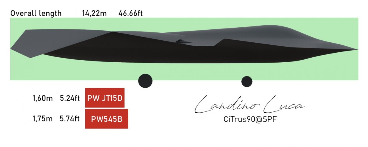
So, if the aircraft in question were a demonstrator the same size of the Boeing Bird of Prey, for example, these would be the relative dimensions between the airframe and the engines (do keep in mind that their diameter is not to scale in my drawing, only their length):
Bandit - side engines small.jpg
The red boxes represent the overall length of the PW JT15D (the turbofan used by both the BoP and the Model 401) and of the PW545B (the PW535, which is slightly shorter than the PW545, is used by the Model 437).
 
Last edited by a moderator:
For a series of reasons, some of which I explained above, I expect this aircraft to be a demonstrator similar in scale to BoP or Model 401.
That's a fair enough assumption

I think it's more likely that they'd be looking to demonstrate the controllability of the novel configuration over a wide flight envelope rather than just low speed. But who knows?
 
So these are just preliminary shapes of what I have. A good friend* of mine eluded that if HE were designing his own jet that the intakes would be DSI and undermounted because the maneuverability requirement needs to be kept with a would-be demonstrator pulling high amounts of AOA. Furthermore, variable DSI cones are a VERY reasonable bridge gap to get the LO aspects of the inlet while being able to get past 1.4-1.8 comfortably. I haven't done it yet, but apparently all moving wing tips may as well be a good bridge gap solution for solving Directional stability but are seen as necessary. Imagine like having a mini YF-23 tail section on your wingtip. But this is all hypothetical of course.
 

Attachments

  • KXTABIRD1.png
    KXTABIRD1.png
    17.5 KB · Views: 79
  • KXTABIRD2.png
    KXTABIRD2.png
    17.6 KB · Views: 72
Last edited:
Asked differently, what does “full-scale” mean to you (or Will Roper!)?
What it means to Will Roper, I have no idea. We should probably ask him?
To me it means the same thing that Overscan said here as well:
Full scale here meaning manned aircraft size, not a subscale UAV I think. I don't think you can conclude the AII-X was the same size as the F-47.

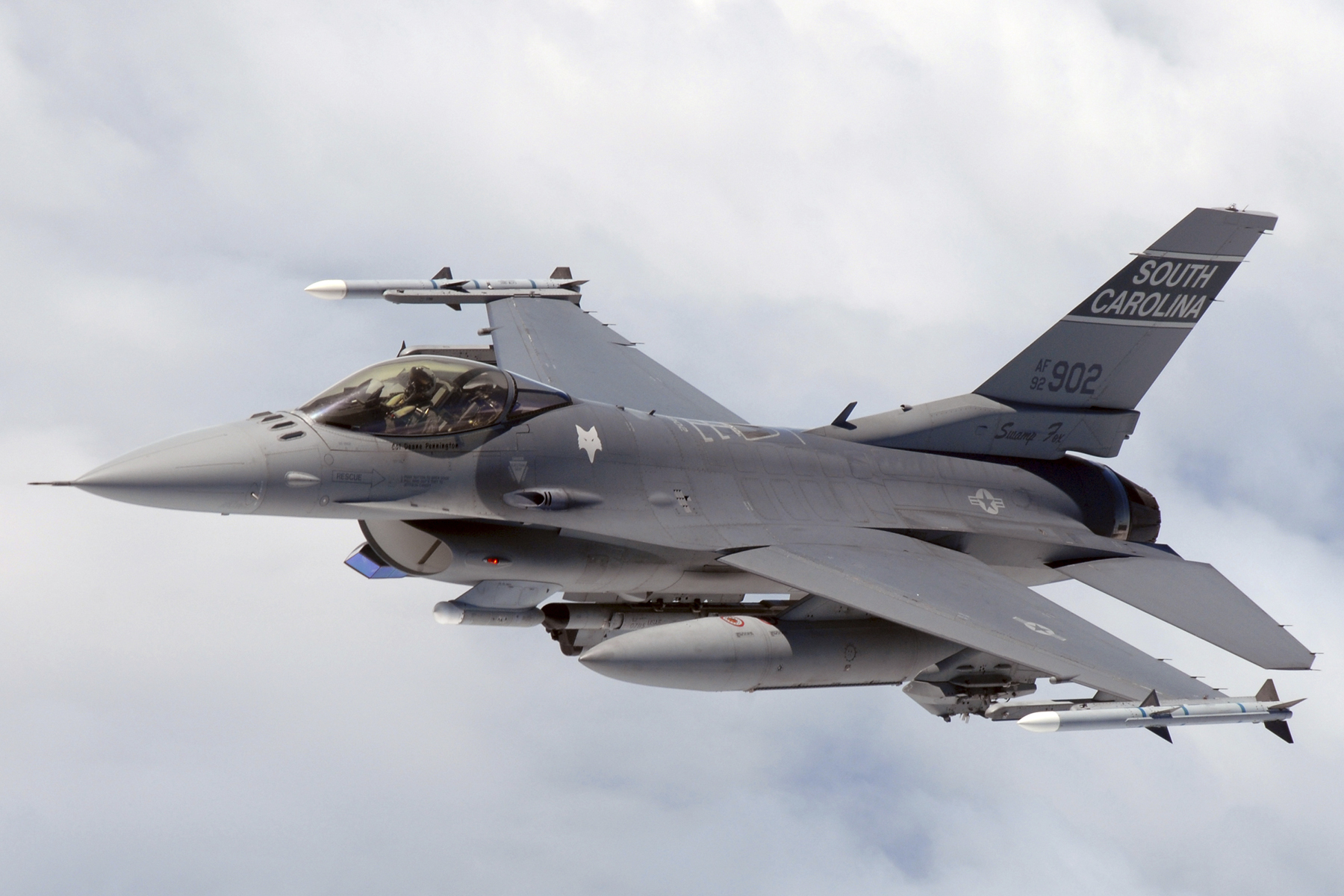
This is a "full-scale" F-16:
F16_SCANG_InFlight.jpg

This is a "full-scale" 1:48 model of an F-16:
fsm-wb0707_12.jpg

A bit of a sarcastic example, but it is meant to emphasize that this is the same thing as saying "full-scale F-47" vs "full-scale flight demonstrator for the F-47".
From a semantics point of view "full-scale" here gives no reference or clues about size.
It only excludes that the demonstrator is a smaller-scale test article of the final demonstrator.

Now, why I do think this aircraft is "not-big"?
As I wrote in my opening post, take a look at the lightly colored areas towards the rear of the aircraft caught on thermal camera:
Bandit - landing gear.jpg
I believe those to be the landing gear bays, which appear white/hot because, since they are open, we are catching a glimpse of the internal structure of the aircraft close to the engines.

Those white streaks are long (significantly so) when compared in length to the rest of the airframe.

So there are only 2 options for this, in my opinion:
- either this airplane's landing gears are as long as a Concorde's and that's why the bays need to be that long in comparison to the overall length of the aircraft
or
- the landing gears are proportional to the rest of the aircraft's dimensions, which implies that the aircraft is on the smallish side

Keep in mind that, if the landing gears were to be very long, the wheel that we can sort of guess in screenshot #2 in my original post would be a lot further apart (downward) from the rest of the black silhouette of the aircraft, because you have to imagine the wheel as positioned at the extremity of a swinging arm (the landing gear itself).
So the longer the gear bay in order to house the landing gear is, the further away from the silhouette would be the wheel.

A good friend* of mine eluded that if HE were designing his own jet
As I stated at the start of the thread, I'm trying to base myself only on what's visible from the available footage.
From what I see, especially where the landing gear appears to be, it seems less probable to me that the intakes could be on the bottom of the aircraft, but I could be wrong.

because the maneuverability requirement needs to be kept with a would-be demonstrator pulling high amounts of AOA. Furthermore, variable DSI cones are a VERY reasonable bridge gap to get the LO aspects of the inlet while being able to get past 1.4-1.8 comfortably.
And this is why I'm trying to base myself only on the available footage: what is this aircraft meant to be a demonstrator of? Does it need to pull high alpha maneuvers? Does it need to be fast? Or is it meant to demonstrate other capabilities?

I don't want to inject my own bias into my reconstruction and I'm trying to stay as neutral as possible. The question shouldn't be "what I want this aircraft to be" or "what I think this aircraft should do", but only "what do I see from the material that is available to me at this time?".
 
I dont think we should read too much into the semantics of what a public official said. If we assume that hes a normal guy, he probably didnt labor himself with finding the exact and precise wording to describe the demonstrator with perfect clarity. I know if I was speaking on a classified topic and keeping it generic to the press, I certainly wouldn't bother finding the right words to perfectly describe the project. So when he says a full scale demonstrator, Im inclined to believe that its at least a manned jet or a actual fighter sized thing and not something like the X-36. That may or may not be applicable to whatever this is.

With respect to what is depicted in here, it looks like what I would expect a twin engine aircraft to be. I interpret the hot areas to be two separate engines because they line up generally with the center line of the two triangular trailing edges (or the W shape on the aft of the aircraft). I'm not sure why they would build a twin engined subscale demonstrator unless it's a full sized aircraft - as in a manned, fighter sized aircraft. Having said that - BoP was manned too and could be considered a "full scale" aircraft, but again - what good reason is there to put two engines even on a BoP sized aircraft?
 
I dont think we should read too much into the semantics of what a public official said. If we assume that hes a normal guy, he probably didnt labor himself with finding the exact and precise wording to describe the demonstrator with perfect clarity. I know if I was speaking on a classified topic and keeping it generic to the press, I certainly wouldn't bother finding the right words to perfectly describe the project. So when he says a full scale demonstrator, Im inclined to believe that its at least a manned jet or a actual fighter sized thing and not something like the X-36. That may or may not be applicable to whatever this is.

With respect to what is depicted in here, it looks like what I would expect a twin engine aircraft to be. I interpret the hot areas to be two separate engines because they line up generally with the center line of the two triangular trailing edges (or the W shape on the aft of the aircraft). I'm not sure why they would build a twin engined subscale demonstrator unless it's a full sized aircraft - as in a manned, fighter sized aircraft. Having said that - BoP was manned too and could be considered a "full scale" aircraft, but again - what good reason is there to put two engines even on a BoP sized aircraft?
We can take the XST relationship to F-117 as an example. A twin engine configuration being necessary to replicate the features, like nozzles design and associated RCS features etc. intended for the NGAD that would otherwise be too unrepresentative in a single engine design.
 
Last edited:
At the end of it all, we all know someone here has a photo of it but at the risk of it just being absolutely devoured by external sources it won't be shared. He did say it isn't some extravagant vehicle so id say maybe hornet to raptor size? If you were feeling VERY eager in dealing with what is seen, heck it could be using OTS gear from a hornet! Could go for a stretch and call the tiny under protrusion a hornet wheel at 30 inches diameter and try to back work an aircraft dimension? Maybe be a little bit of a stretch again but who knows!
 
... so id say maybe hornet to raptor size? If you were feeling VERY eager in dealing with what is seen, heck it could be using OTS gear from a hornet!
A thought: if you assume the white streaks are turbofan engines 15.5-ft long, then the Project_Fear aircraft roughly scales to 62 ft long.

F-14D: 62.7 ft
F-22A: 62.1 ft
F/A-18E: 60.3 ft
E-2D: 57.7 ft
F-35C: 51.5 ft

My 2 cents -- the image is the DARPA/Navy AII aircraft, aka YF-45D, first flown in 2019.
 
We can take the XST relationship to F-117 as an example. A twin engine configuration being necessary to replicate the features, like nozzles design and associated RCS features etc. intended for the NGAD that would otherwise be too unrepresentative in a single engine design.

At the time that the XST configuration was developed there was no F-117 in the works. The XST wasn't a "scaled" demonstrator for the F-117. Instead, the success of XST drove USAF to request a combat aircraft derived from it.
 
At the time that the XST configuration was developed there was no F-117 in the works. The XST wasn't a "scaled" demonstrator for the F-117. Instead, the success of XST drove USAF to request a combat aircraft derived from it.
Isn't the same rough relationship applying here as well, since this (apparently) Boeing All-X demonstrator flew in 2019 and Boeing was selected to build F-47 just last year? Or do you think this demonstrator will be more distantly related to F-47 than XST was to F-117?
 
A thought: if you assume the white streaks are turbofan engines 15.5-ft long, then the Project_Fear aircraft roughly scales to 62 ft long.

F-14D: 62.7 ft
F-22A: 62.1 ft
F/A-18E: 60.3 ft
E-2D: 57.7 ft
F-35C: 51.5 ft

My 2 cents -- the image is the DARPA/Navy AII aircraft, aka YF-45D, first flown in 2019.
The F-22 is also 62 ft long. I've heard that there is a length limit related to Hardened Aircraft Shelters that is also around 62 ft.
 
Isn't the same rough relationship applying here as well, since this (apparently) Boeing All-X demonstrator flew in 2019 and Boeing was selected to build F-47 just last year? Or do you think this demonstrator will be more distantly related to F-47 than XST was to F-117?

An awful lot of things changed between when the demonstrator was designed and when the F-47 was designed. Technology maturity, requirements, etc.
 
Do you think Voodoo II eventually flew with an adaptive cycle engine at some point or was that uninteresting or was the juice was otherwise not worth the squeeze?
2 August 2025
The Boeing AII-X Navy aircraft demonstrated very high electrical power generation with non-adaptive engines. This was not a Navy requirement, Boeing demonstrated this knowing it was of more interest to the Air Force.
Time is a flat circle...
 
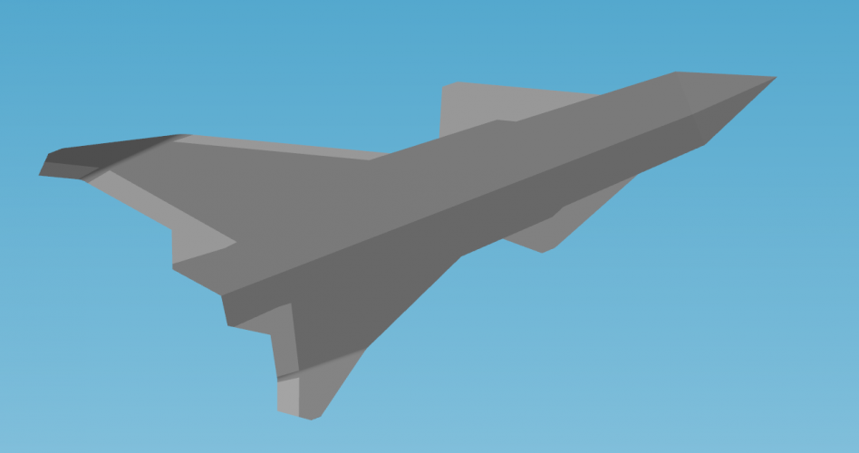
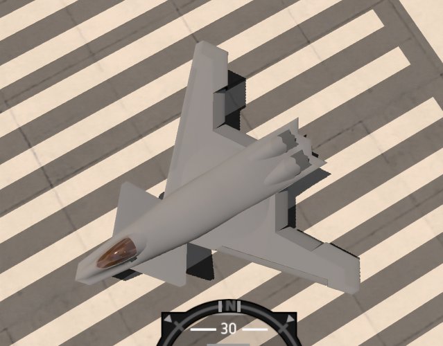
Trying to build a flyable model in simple planes 2. The planform works exceptionally well. Engine layout is purely for testing. What cant be seen is all moving wing tips. Appears to be very agile.
 

Attachments

  • AII-X WIP.png
    AII-X WIP.png
    816.3 KB · Views: 127
These are the 3 frames that I believe to be the most useful for attempting a visual reconstruction of the aircraft in question.
The first picture shows the silhouette of the planform, almost perpendicular to the camera's POV. The second one shows the aircraft starting to fly away from the observers, together with the hint of a landing gear on the left side of the vehicle. The final frame shows the aircraft now getting further away from the camera, where the angles of both the main wings and canards in relation to each other are now visible and, again, a possible hint of a frontal landing gear.

As I pointed out in a previous post in another thread as well, all frames of the overflight show an area of discontinuity in coloration on the underside of the aircraft. This area is limited to a pair of symmetrical stretches at the rear of the vehicle.
My suggestion is that these differently colored areas (which appear white and are, hence, hotter than their surrounding surfaces) correspond to openings on the underside of the aircraft, compatible with landing gear bays. The heat we see is very probably seeping from the nearby engines.
Screenshot #2 is also suggestive (even more so than screenshot #3) of the presence of a lowered landing gear.

Given the length of these white stretches, that I believe to be the landing gear bays, and the position of the wheel (visible in screenshot #2), my assumption is that this aircraft is quite small.
How small precisely, I cannot say, since no marks in the background are available for reference and to conduct measurements, but it would certainly be compatible in size with the Boeing Bird of Prey or the Scaled Composites Model 401's overall dimensions.
Nice 3D model. But it doesn't quite match what is shown. wtna7 has done a pretty good job at matching, though, we can only be certain in the length axis and limited certainty for the width. Your wing tips are certainly too wide in terms of span width.

Youtuber OSINT-cschmitz : www.youtube.com/watch?v=g_FMO_Zl484 has done some AI analysis that clearly outine presumely engine bays rather than wheel bay. If you look at the video footage youd woud see bright patches rather than lines. This matches typical engine bottom hot area usually covered by titanium plates. The AI suggests leakage through the bay gaps, though. The outines aren't perfect and might follow the OML.

But keep in mind the video footage we see has gone through at least 5 stages of manupuations:
1. camera image processing (see edge rendering)
2. encode for media format for saving
3. film crew video post-processing & upscaling
4. encode for media format for uploading
5. youtube streaming optimization & re-encoded video for different screen formats
Hence, the pixels we see are not reliable in the slightest. Not to mention the 0.2 m error of margin per 1000 m distance per original camera pixel. Video pixel error margin is another thing.

Anyhow, I got at least a good length to work with. It's just the wingspan and aft details that need closer investigation.
A few things look strange due to the distortion/flimsyness. I still need to work this out.

As for “full-scale”, before I woud agree with "being manned" but since "optionally manned" is thing the simple answer is:
1. no special care for miniaturizing work and adapting designs to fit a scaled model
2. no backworking/calculating result for a full-scale aircraft
3. can use all existing of the shelf aircraft parts and systems

I haven't watched the whole video yet but apparently the aircraft was caught on film before the flyover. The fim crew just didn't realized it. ;)
 
wtna7 has done a pretty good job at matching, though, we can only be certain in the length axis and limited certainty for the width
I disagree.

Not to take anything away from wtna7's efforts, but trying to match a 2d shape like the representation he did to a 3d object, you are bound to encounter several issues.
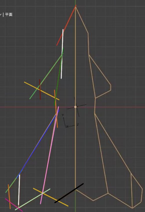
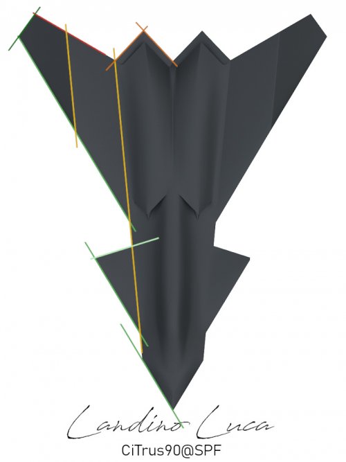
In his attempt, the most obvious shortcoming would be trying to keep edge alignment:
wtna7 edges.jpg
There are more than 11 different edges here.

Mine has 6:
Bandit - edges.jpg
I feel that the trick at the moment needs to be to reduce that number down to at least 4 edges while still being able to make a 3d shape compatible with (different angles of) the footage recorded.

Your wing tips are certainly too wide in terms of span width.
I agree.
This is the issue I've been having so far with trying to keep coherence among the different angles of the aircraft, while (at the same time) being constrained by respecting edge alignment as much as possible.
If anybody had any suggestions in order to help me in this area, I'd appreciate it a lot.

Youtuber OSINT-cschmitz : www.youtube.com/watch?v=g_FMO_Zl484 has done some AI analysis that clearly outine presumely engine bays rather than wheel bay. If you look at the video footage youd woud see bright patches rather than lines. This matches typical engine bottom hot area usually covered by titanium plates.
Disagree, again.

Screenshot #1 no visible bright patch:
Screenshot 1.jpg
Screenshot #2 visible heat patches:
Screenshot 2.jpg
Screenshot #3 visible heat patches:
Screenshot 3.jpg
Screenshot #4 minimally visible heat patches (mostly on one side only):
Screenshot 4.jpg
Screenshot #6 no visible heat patches:
Screenshot 6.jpg

If the heat were showing through the surface of the OML, it would be visible from all angles as the aircraft flies overhead. Since it's not, that means that the hot area is not on the surface, but inside an opening in the aircraft OML. So, as the aircraft comes head on, we do not see inside the landing gear bay, because it's shielded by the geometry of the aircraft itself or by its landing gear doors. Then, once it's almost overhead, we see the heated area and, again, once it starts to fly further away, we don't see the heat patches anymore.
 
I disagree.

Not to take anything away from wtna7's efforts, but trying to match a 2d shape like the representation he did to a 3d object, you are bound to encounter several issues.
In his attempt, the most obvious shortcoming would be trying to keep edge alignment:
As I've said the footage & resolution are very bad to be reliable. It's originaly 640x480. This means the 2160p video from youtube translates 1px to 4.5 px.
If the heat were showing through the surface of the OML, it would be visible from all angles as the aircraft flies overhead. Since it's not, that means that the hot area is not on the surface, but inside an opening in the aircraft OML. So, as the aircraft comes head on, we do not see inside the landing gear bay, because it's shielded by the geometry of the aircraft itself or by its landing gear doors. Then, once it's almost overhead, we see the heated area and, again, once it starts to fly further away, we don't see the heat patches anymore.
I did say the AI indicates it's the gaps due to above reason and as follows
Your assumption about the IR detail is wrong because you think what we see is 1:1 in pixel and miss the fact that detais smaller than the original camera resolution is being ignored and won't show up, especially at a distance. While things that are somehow relatively bright are enhanced via software to highlight it (see edge enhancement). We see them well but in reaitly may not be big. The AI is able to discern this because its perception is more nuanced.
You have to adjust your analysis from case to case.

There are more than 11 different edges here.

Mine has 6:
View attachment 815231
I feel that the trick at the moment needs to be to reduce that number down to at least 4 edges while still being able to make a 3d shape compatible with (different angles of) the footage recorded.

I agree.
This is the issue I've been having so far with trying to keep coherence among the different angles of the aircraft, while (at the same time) being constrained by respecting edge alignment as much as possible.
If anybody had any suggestions in order to help me in this area, I'd appreciate it a lot.
That's just your will & wishfull asumption of how it should be. That's why it diverges right away.

I do agree it's preferable if all or as many as possible are aligned but aerodynamic requirements for a fighters don't always agree just look at the F22/F35 and other research ones. The nose and plenty small or in between sections have their own angles.
Since this is about replicating the aircraft we have to fit the form as close as possible first and then guess and apply possible angles withing the error margin of the camera resolution.

For this reason I'm critical and held up about the spanwise size & details as well as the aft engine nacelles.
The drooped wingtips likely have deceiving angles on the panform while more reasonable angles as separate wing section.
 
As I've said the footage & resolution are very bad to be reliable.
So.
The footage is unreliable enough that what I point out and say is wrong.
But then it's reliable enough that what you or others say and point out is right.

Ok.

The AI is able to discern this because its perception is more nuanced.
No.
Absolutely not.
Any image that goes through AI processes is altered in ways that make any attempt at reconstruction futile. AI is the least useful thing one could make use of here, especially when resolution is so low.

That's just your will & wishfull asumption of how it should be. That's why it diverges right away.

I do agree it's preferable if all or as many as possible are aligned but aerodynamic requirements for a fighters don't always agree just look at the F22/F35 and other research ones.
You don't think that the F-22 and F-35 have edge alignment?

Your last two statements tell me all I need to know about this discussion, so I think it's better for the both of us to spend our time differently than replying at each other.
I'll certainly find better ways to spend mine for sure.
 
All right.
This is what I got so far.
Since we know the observation and landing location I went ahead and estimated velocity and distance. This is the single most decisive factor and key source of possible origin error on my part.
0001184-composition53,14°.png
This gave me a length for the center fuselage (wings not included) of
17.469 m ±0.7 m speed range ±(0.409/0.425/0.443)m speed error margin
The aircraft was slowing down at a rate of about 0.6 m/s^2
I tried to narrow down the width & details by measuring from the tail view but the error margin for 1 pixel doubled compared to overhead flyby.
​0045807-composition.png
I don't see a way to determine the drooped wing tip's true form & angle with reasonabe certainty.
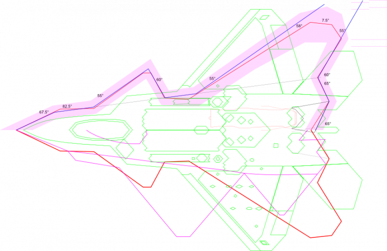
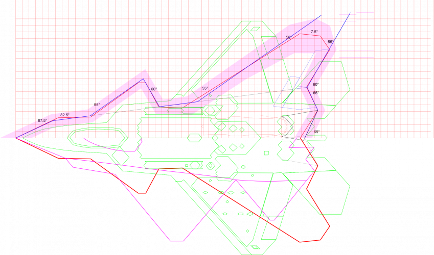
So here's a comparison view with possible edge angles and margin of error area. I used wtna7's panform as a base scaled to my findings and threw in other designs of note as well as the engine patent drawing.
 

Attachments

  • projectfear-NGAD-demo-x1.png
    projectfear-NGAD-demo-x1.png
    92.1 KB · Views: 77
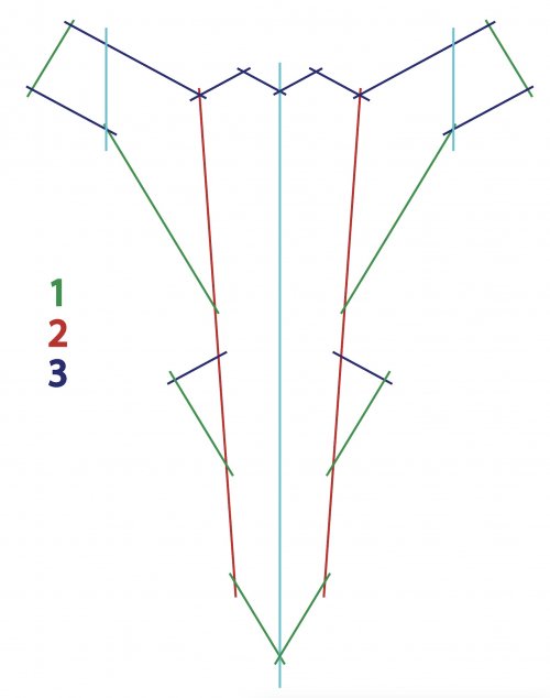
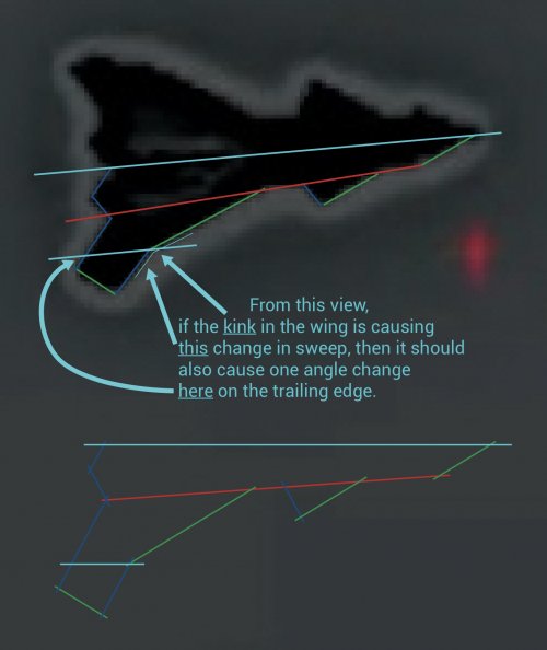
I know it may just be the kink on wing giving that impression from that angle, but I wonder if the leading have two sweep angles, the one further out being aligned with the wing trailing edge.
Roughly Like so :
4Angles.jpg
EDIT : That can make only 3 angles, not 4 :)
Also, it seems to me there is more space between the nose and the canards.

EDIT again (don't hesitate to tell me if I bother you with my ideas @CiTrus90 ) :
To further illustrate my idea of 2 wing sweep angles,
2anglesLE.jpg
 
Last edited:
I've added a camera pixel grid (overhead case but ofc not at camera angle) and adjusted the wing edgeline which shows the possible wiggle room & interpretation we are dealing with this uncertainty.
 

Attachments

  • NGAD-demo-xxx1grid.png
    NGAD-demo-xxx1grid.png
    332.3 KB · Views: 86
EDIT again (don't hesitate to tell me if I bother you with my ideas @CiTrus90 ) :
Absolutely no issue at all, I very much appreciate your inputs!
I was just too busy IRL to give a proper response yesterday.

While tinkering at the initial 3d of my model, I tried modeling the outer portion of the wings with a different sweep. It was the solution that came closest to matching the shape of the aircraft from the different angles we see from the footage.
I'm still on the fence, though, if that might be what we see or if it's just an impression due to the combination of angles that the wing goes through. From certain angles even the BoP appears to a double sweep for its wings, but I don't think that's the case.
 
The F-22 is also 62 ft long. I've heard that there is a length limit related to Hardened Aircraft Shelters that is also around 62 ft.
Only if you want to restrict yourself to the size of old HAS without considering new might be built. Foolish IMO. How often have either F-15s or F-22 been parked in them in the last 20 years?
 
So there are only 2 options for this, in my opinion:
- either this airplane's landing gears are as long as a Concorde's and that's why the bays need to be that long in comparison to the overall length of the aircraft
or
- the landing gears are proportional to the rest of the aircraft's dimensions, which implies that the aircraft is on the smallish side
The landing gears retract rearward. I was the only person in the F-47 thread that produced an image of a rearward retracting main gear. Here is my post.

https://www.secretprojects.co.uk/th...he-boeing-f-47-ngad.45793/page-32#post-868325

Also the landing gear has to be tall to allow a JASSM missile and trolley to slide under the aircraft. Remember the Boeing All-X demonstrator was designed with the US Navy in consideration. The delta canard design also lands with slightly higher angle of attack so the tall landing gear will be needed to provide enough tail hook clearance for the Navy variant. A landing gear that looks as tall as Concorde wouldn't be unusual.

Regarding size Boeing would design the aircraft to be as close to the aircraft carriers size limit. That is about F-22 size. The F-35C is already within 20% of the weight of the F-14 and A-3 which were the heaviest aircraft to operate from a carrier. So to get a generational improvement over the F-35C it has to max out the carrier size limit.


but apparently all moving wing tips may as well be a good bridge gap solution for solving Directional stability but are seen as necessary. Imagine like having a mini YF-23 tail section on your wingtip. But this is all hypothetical of course.
This does make perfect sense. Instead of having landing flaps on the trailing edge the entire wing tip could rotate down. The extra lift generated from the wing tips would then be a couple metres further forward compared to the trailing edge. This would reduce the pitching down moment while giving more lift. When combined with front canards providing lift it could allow a landing speed slower than the F-14 while being heavier than the F-14.

As this video clearly shows the landing gear down the wing tips might simple be in the landing configuration. So all the renderings posted showing towards tips might be completely wrong.
 
I have been working on the flight model and developing the control laws for it with my 988-119 to validate them. Once Ive nailed them down I move the codes to the AII-X for cross validation. Watched a good amount of X-36, 31, and read the design papers for the gull wing design to develop the controls for it. I have put a representative TVC system into my model with deflections based on the exhaust image I shared. So far so good though!
 

Attachments

  • Screenshot_20260619_091419_SimplePlanes.jpg
    Screenshot_20260619_091419_SimplePlanes.jpg
    4.1 MB · Views: 89
Also the landing gear has to be tall to allow a JASSM missile and trolley to slide under the aircraft. Remember the Boeing All-X demonstrator was designed with the US Navy in consideration.

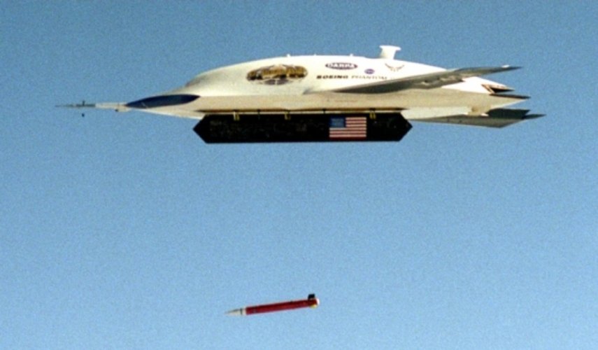
Why would an x-plane need to carry a standoff weapon?
 

Attachments

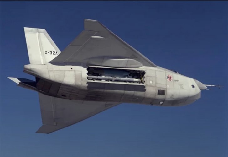
  • X-45A X-plane dropping bomb.jpg
    X-45A X-plane dropping bomb.jpg
    372 KB · Views: 64
  • X-32 X-plane carrying missile.jpg
    X-32 X-plane carrying missile.jpg
    197.7 KB · Views: 49
Last edited by a moderator:

Similar threads

Back
Top Bottom