
You are using an out of date browser. It may not display this or other websites correctly.
You should upgrade or use an alternative browser.
You should upgrade or use an alternative browser.
Why the intermeshing rotor helicopters are so few?
- Thread starter Pasoleati
- Start date
- Joined
- 13 August 2007
- Messages
- 7,179
- Reaction score
- 6,585
Intermeshing rotors have some issues
You need to synchronise the rotors to prevent them colliding.
Next to that neither rotor lifts directly vertically, which reduces efficiency per each rotor.
Also the controls are more complicated, do increasing collective pitch on the blade sets.
This all result end in higher maintain cost on rotors sets.
Compare to traditional Helicopter
persil
All rotorcraft enthusiast
Also ground-crew safety is kind of an issue. Otherwise I am really fascinated by that layout. Do you know how many various inermeshing helicopters were built or designed?
Pasoleati
I really should change my personal text
- Joined
- 29 June 2012
- Messages
- 497
- Reaction score
- 170
Ground crew safety? Any more unsafe than tail rotors...
My prime reason for intermeshing arrangement would be the elimination of:
-Unnecessary long airframe.
-The potential for loss of tail rotor effectiveness. I have read not a few accident reports in which the reason has been loss of tail rotor effectivess without any technical fault. It is a built-in characteristics impossible to avoid with the tail rotor system.
persil
All rotorcraft enthusiast
Well, when you work around helicopters, then you are accustomed to the fact, that there is big deadly mass spinning, but above your head (when on nominal rpm - Ka-26 has lower rotor main rotor blade tip at front position when at rest not much higher than my cojones are). Most helicopters are like that and it rarely happens that specific person on the ground has to do with only one type of helicopter all the time. So if such man will happen to approach a say K-MAX and he will do it from a side, well, you would not like to see the outcome.Ground crew safety? Any more unsafe than tail rotors...
persil
All rotorcraft enthusiast
On the other thought, answering your original question, I think that it is technically more challenging when it comes to gearing.
Let me briefly explain:
Most helicopter companies started with usually a brilliant man who used to build a prototype aircraft and then, when it proved is reliable and safe - and joyful of course - usually investors find their way to him and a company is established. Also usually this first layout (Sikorsky) or one of firsts (Piasecki) is the use as the one for all the future projects - simply because of biggest experience in that one solution.
When that said brilliant man is prototyping - he normally don't have much funds and is lacking big 3+ axis CNC machines, or in the past specialized tools for specific task in manufacturing. I am going to the gear wheels. It is required element for shaft driven helicopters and it is not easy to make precision gears by an unskilled in this subject person - you may be great aerodynamicist but will fail on manufacturing gears, especially when you are just couple of notches above amateur level.
Thus these guys usually salvage such parts from available places - often cars - as was the case for wheels in the R22 and R44 main transmissions. This source of wheels offers shaft angles of 0 deg and 90 deg. In modern differentials even the input pinion shaft axis is lowered so it is not crossing the main shaft. Other angles - which are essential for intermeshing helicopter - are an extremely rare thing.
You can still make a prototype intermeshing helicopter with only 90 degree and 0 degree wheels but it is less efficient (heavier + gears losses)
Last edited:
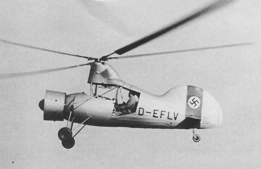
well, the argument against it it, that this design is quite the oldest design for any usefull helicopter:
 en.wikipedia.org
Flettner Fl 265 - Wikipedia
Nik
ACCESS: Top Secret
- Joined
- 15 July 2009
- Messages
- 1,149
- Reaction score
- 820
I'm reminded that several intermeshing designs --Hiller ??--proved very, very good at hoisting hefty loads high into eg the Alps, could get onto LZs much smaller and windier than trad, long-tail designs. Snag was their flanks' 'Grim Reaper' aspect...
Did 'intermeshing' helos evolve from intermeshing 'auto-gyros' ??
Co-axial / contra-rotating rotors do keep their sweep from the bystanders, albeit at expense of twice the 'up-mast' complexity...
FWIW, I've a soft spot for the skeletal 'Sky Crane', unburdened by 'overheads' of a passenger cabin...
Did 'intermeshing' helos evolve from intermeshing 'auto-gyros' ??
Co-axial / contra-rotating rotors do keep their sweep from the bystanders, albeit at expense of twice the 'up-mast' complexity...
FWIW, I've a soft spot for the skeletal 'Sky Crane', unburdened by 'overheads' of a passenger cabin...
- Joined
- 18 October 2006
- Messages
- 3,890
- Reaction score
- 3,781
If I recall correctly Kaman went with the intermeshing rotors because it was good at picking up heavier loads with minimal increase in downwash due to the heavier weights. It does of course get rid of the risk of a tail rotor in confined areas (logging and urban vertical development) as well.
At least one US helicopter company immediately following WW2 (forgetting at the moment) planned to use the intermeshing rotor method. I do not recall the reason it did not succeed.
At least one US helicopter company immediately following WW2 (forgetting at the moment) planned to use the intermeshing rotor method. I do not recall the reason it did not succeed.
- Joined
- 11 March 2012
- Messages
- 3,016
- Reaction score
- 2,703
Sort of ….I'm reminded that several intermeshing designs --Hiller ??--proved very, very good at hoisting hefty loads high into eg the Alps, could get onto LZs much smaller and windier than trad, long-tail designs. Snag was their flanks' 'Grim Reaper' aspect...
Did 'intermeshing' helos evolve from intermeshing 'auto-gyros' ?
Anton Flettner’s first rotorcraft was a single-rotor auto gyro built during the 1930s in Germany. The. He built a single-rotor auto gyro that could also be flown as a helicopter.
During WW2, Flettner developed several inter-meshing helicopters for the Nazi German Luftwaffe.
His Fl265 pioneered inter-meshing rotors and he went on to build 24 of his Fl 282 helicopter before WALLIED bombing and the end of the war killed that project. Germany tried to stand up an artillery-spotting squadron based on Fl. 282 (2-seater) helicopters, and some other helicopters built by Focke-Wolf, but it was wrecked by the advancing Red Army.
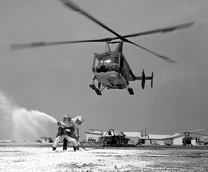
After WW2, Flettner moved to the USA (see Operation Paper Clip) where he joined Kaman helicopters to help them design their HH-43 Husky series of inter-meshing helicopters that primarily served the USAF as fire fighters.
To this day, Kaman K-Max helicopters are still in limited production. K-Max are not very fast, but they make great flying cranes for moving cargo short distances or dropping water on wild fires.
I have stood beside a K-Max and the rotor tips are so far above the ground that it is almost impossible for them to hit ground crew … perhaps only if walking down-slope towards the helicopter.
Part of the reason that K-Max rotor heads are so high is that their rotor shafts extend all the way to the bottom of the fuselage where they connect via synchronizing gears. This synchronizing gears prevent rotor blades from ever getting closer than 90 degrees.
Routing control rods in a K-Max is way simpler than Kamov (co-axial) because you only need a single swash-plate per rotor. Furthermore, Kaman uses Flettner tabs to adjust rotor pitch, so control rods don’t need to transmit much “muscle.” Instead, Flettner tabs work more like servo tabs to re-trim rotor blades while in flight.
Last edited:
- Joined
- 11 March 2012
- Messages
- 3,016
- Reaction score
- 2,703
Kaman synchronizes inter-meshing rotor-blades by extending rotor drive shafts all the way to the bottom of the fuselage where they meet at a pair of bevelled synchronizing gears.You need to synchronise the rotors to prevent them colliding. …
IOW If you look at a Kaman helicopter from the front, you will notice that the rotor masts lean outboard a bit and meet at the bottom of the fuselage.
Kaman’s system is shorter and lighter than the synchronizing shaft on a Boeing/Vertol/Piaseki CH-46 Voyageur/Labrador/Sea Knight.
- Joined
- 11 March 2012
- Messages
- 3,016
- Reaction score
- 2,703
What do you mean?Transmission layout is somewhat complex as well.
Kaman K-Max mounts it’s engine and main gear box on top of the fuselage … like most other helicopters. Both main rotors are driven from that level.
Only lighter-weight synchronizing-shafts extend down to the bottom of the fuselage where they meet with a pair of bevelled synchronizing-gears.
- Joined
- 6 August 2007
- Messages
- 3,034
- Reaction score
- 2,395
Because egg-beaters are ugly.
UCAR has left the chat sobbing

Kiltonge
Greetings Earthling
- Joined
- 24 January 2013
- Messages
- 468
- Reaction score
- 641
The answer is most fundimental - too many moving parts.
However the conventional main and tail rotor arrangement requires a minimum of three gearboxes and lots of highly-stressed driveshafts, plus control rods running the full length of the tail boom.
- Joined
- 11 March 2006
- Messages
- 8,615
- Reaction score
- 3,098
From what I know, tandem rotors need to be synchronised, too, and IIRC, some accidents with the Chinook had their cause in the failure of this synchronisation (see https://aviation-safety.net/wikibase/wiki.php?id=18540 ). whereas I haven't heard this from WWII Flettner, or post-war Kaman types ...Intermeshing rotors have some issues
You need to synchronise the rotors to prevent them colliding.
...
Last edited:
I guess, the turbine reduction gearbox is driving one of the rotorshaft, and half of the torque is transmitted to the bottom to the bevel gears to drive the other shaft.What do you mean?
Kaman K-Max mounts it’s engine and main gear box on top of the fuselage … like most other helicopters. Both main rotors are driven from that level.
Only lighter-weight synchronizing-shafts extend down to the bottom of the fuselage where they meet with a pair of bevelled synchronizing-gears.
It is a fascinating effective design. I did some calculations and came to the conclusion, that a hypothetical Diesel powered Kamax could even cross the Atlantik if all the weight lifting capacity would be used for fuel.
Both models are in production:
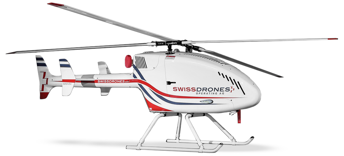
 www.swissdrones.com

 anavia.eu
The intermeshing configuration is a very well working and aerodynamical beautiful system because it is the only real symmetrical lift configuration for helicopters.
The construction effort should not be significantly higher than for a model with a tail rotor, let alone with a coaxial or tilt rotor configuration. The reason for the low prevalence is probably the general reluctance of companies to invest in new technology concepts unless absolutely necessary, especially in the aircraft business.
The Kaman system with its rotor flaps is not really suited for high-speed flight, but this has nothing to do with the intermeshing configuration.
SwissDrones Long-Range VTOL
SwissDrones is specialized in the development, manufacturing, and operation of long-range unmanned helicopter systems for commercial and public safety applications.
www.swissdrones.com
ANAVIA HT-100 - the most advanced VTOL system worldwide.
ANAVIA develops and manufactures innovative UAVs focusing on vertical takeoff & landing systems (VTOL) of up to 500 kilograms.
anavia.eu
The intermeshing configuration is a very well working and aerodynamical beautiful system because it is the only real symmetrical lift configuration for helicopters.
The construction effort should not be significantly higher than for a model with a tail rotor, let alone with a coaxial or tilt rotor configuration. The reason for the low prevalence is probably the general reluctance of companies to invest in new technology concepts unless absolutely necessary, especially in the aircraft business.
The Kaman system with its rotor flaps is not really suited for high-speed flight, but this has nothing to do with the intermeshing configuration.
Last edited:
At least one US helicopter company immediately following WW2 (forgetting at the moment) planned to use the intermeshing rotor method. I do not recall the reason it did not succeed.
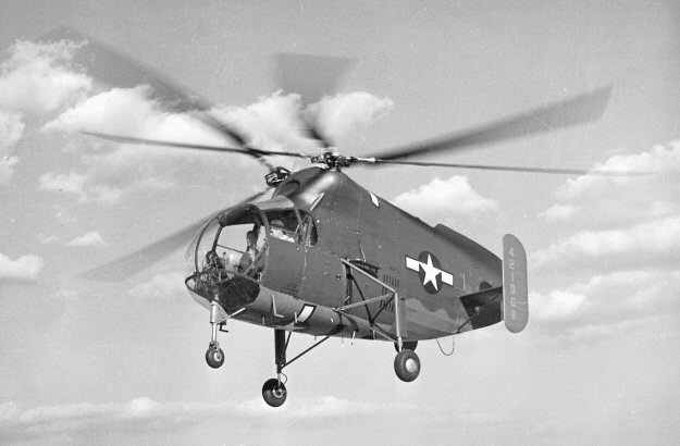
Kellett XR-8 - Wikipedia
persil
All rotorcraft enthusiast
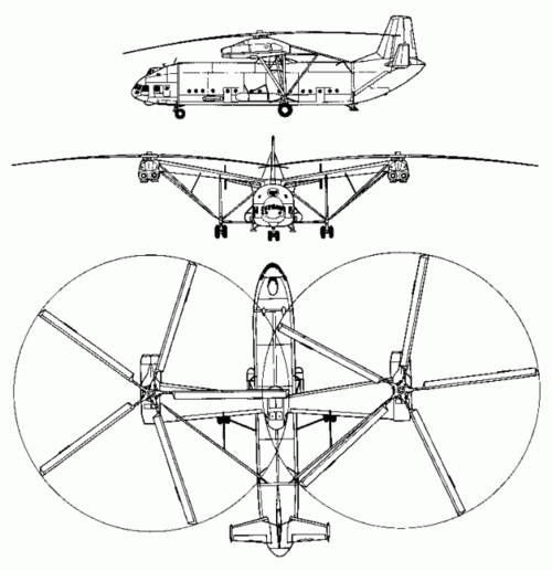
Kellett is possibly the best example of yet another limitation - number of blades. I have never seen intermeshing design with more than three blades - it is possible to design, but the distance between hubs must be greater - this translates to heavier weight of transmission.Kellett XR-8 - Wikipedia
So for smaller size helicopter this layout seems to be advantageous in regard to lift capability, but if you want even more lift capability then bigger number of blades is the way to go (other wise you can reach materials limit) - like CH-53 - went from 6 to 7 blades, like Mi-26, which has 8 blades.
So you can still have six blades.Kellett is possibly the best example of yet another limitation - number of blades. I have never seen intermeshing design with more than three blades - it is possible to design, but the distance between hubs must be greater - this translates to heavier weight of transmission.
So for smaller size helicopter this layout seems to be advantageous in regard to lift capability, but if you want even more lift capability then bigger number of blades is the way to go (other wise you can reach materials limit) - like CH-53 - went from 6 to 7 blades, like Mi-26, which has 8 blades.
Hi,
Wasn't the Mil Mi-12 using intermeshing blades? It had 5-bladed rotors.
Regards,
Henning (HoHun)
I have never seen intermeshing design with more than three blades - it is possible to design, but the distance between hubs must be greater - this translates to heavier weight of transmission.
Wasn't the Mil Mi-12 using intermeshing blades? It had 5-bladed rotors.
Regards,
Henning (HoHun)
persil
All rotorcraft enthusiast
No, that one (actually called V-12) was a classic side-by-side layout - at least for me - you may argue where is the border between the two - I would say if each rotor has its own dedicated gearbox then it is not a intermeshing - it may be overlapping though.Hi,
Wasn't the Mil Mi-12 using intermeshing blades? It had 5-bladed rotors.
Regards,
Henning (HoHun)
Or maybe better would be to say if blades of the first rotor goes over the hub of the second rotor ( and vice versa), then it is intermeshing.
Attachments
- Joined
- 11 March 2012
- Messages
- 3,016
- Reaction score
- 2,703
Kaman briefly experimented with 3-bladed main rotors (for a total of 6 blades) but saw no advantage and dropped the concept.So you can still have six blades.
This brings us to the vast increase in complexity between 2-bladed rotors and those with more blades. As Young and Bell figured out early (early 1940s) 2-bladed rotors can be built semi-rigid with vastly fewer moving parts.
In forward flight, the retreating blade wants to lead (speed up) at exactly the same time as the advancing blade wants to lag (slow down) they balance and do not need any lead-lag hinges.
Similarly, the retreating blade wants flap downwards at the same time as the advancing blade wants to flap upwards, a single teetering hinge/bearing can allow both movements simultaneously.
Hence 2-bladed rotors only need feathering (pitch change) hinges/bearings for a parts count an entire order of magnitude less than 3-blades rotors.
BlackBat242
OK, I changed my personal text ;)
- Joined
- 10 April 2013
- Messages
- 814
- Reaction score
- 2,007
The USAF also used the HH-43B in Vietnam as a CSAR helo*. They got 218 (18 were radial-engine powered and stayed stateside, the other 200 were turbine-powered).Sort of ….
After WW2, Flettner moved to the USA (see Operation Paper Clip) where he joined Kaman helicopters to help them design their HH-43 Husky series of inter-meshing helicopters that primarily served the USAF as fire fighters.
The USMC got 81 5-seaters for utility and rescue work (replaced by the UH-1E).
The USN got 54 3-seaters, used mostly at land bases, and limited shipboard rescue use.
Note that the USN/USMC 43s were all piston-engined, and the engine was located in the aft fuselage, leaving only the cockpit, which had room for 5 if fitted with seats behind the pilot/copilot seats. The display example below has no rotors because few remain, being made of laminated wood, and thus not suited for long outside exposure.

The turbine-powered ones had the engine above the cabin, and the emptied aft fuselage area had canvas folding seats for 4 personnel (in addition to the 5-man front area).
* The USAF's Huskie was deployed overseas during the Vietnam War; several detachments of the Pacific Air Rescue Center, the 33d, 36th, 37th, and 38th Air Rescue Squadrons, and the 40th Aerospace Rescue and Recovery Squadron operated the type. Personnel came to commonly refer to the aircraft by its call sign "Pedro". Early on, the rotorcraft's limited range proved to be a hindrance to operations; some crews resorted to an improvised additional fuel tank housed within the aft compartment, increasing fuel capacity by roughly 75 percent. During the conflict, the HH-43 flew more rescue missions than all other rotorcraft combined, largely due to its unique hovering capability; between 1966 and 1970, the type performed a total of 888 combat rescue, comprising 343 aircrew rescues and 545 non-aircrew rescues.

1966 Operation Abilene, a joint US-Australian action also known as the Battle of Xa Cam My saw the HH-43B in action:

Last edited:
- Joined
- 3 June 2011
- Messages
- 17,369
- Reaction score
- 9,129
"Flying Shithouse Kaman HH-43 Huskie"
persil
All rotorcraft enthusiast
Reality is usually more complex:Kaman briefly experimented with 3-bladed main rotors (for a total of 6 blades) but saw no advantage and dropped the concept.
This brings us to the vast increase in complexity between 2-bladed rotors and those with more blades. As Young and Bell figured out early (early 1940s) 2-bladed rotors can be built semi-rigid with vastly fewer moving parts.
In forward flight, the retreating blade wants to lead (speed up) at exactly the same time as the advancing blade wants to lag (slow down) they balance and do not need any lead-lag hinges.
Similarly, the retreating blade wants flap downwards at the same time as the advancing blade wants to flap upwards, a single teetering hinge/bearing can allow both movements simultaneously.
Hence 2-bladed rotors only need feathering (pitch change) hinges/bearings for a parts count an entire order of magnitude less than 3-blades rotors.
At least the Kaman K-Max although it has teetering hub and only two blades, it also has lead-lag hinges:


Complexity when we talk about Mr Kaman designs is also a bit elevated: apart from necessary flight control system elements (swasplates, scissors and pitch links) there is more of such elements as Kaman uses servo flaps on the outer parts of the blades, and those are controlled by a dedicated long push-pull tube in the blade, extra bellcrank, counterweight element and some other elements.

But it is beautiful. And feathering hinges? Nope - K-Max has none. It also has wooden blades and its small torsional stiffness allow it to change pitch angle - actuated aerodynamically through the servo flap. So - something for something.
BlackBat242
OK, I changed my personal text ;)
- Joined
- 10 April 2013
- Messages
- 814
- Reaction score
- 2,007
I'm not sure about the "improvised additional fuel tank housed within the aft compartment" mentioned above... but the January 1957 issue of the Kaman newsletter discussed (on page 5) a newly certified 50-gallon removable tank for the HH-43B/F - two could be placed in the cabin under the seats, adding 30 minutes flight time per tank (1 hour total), and removal or replacement took 5 minutes per tank (they were filled in-place in the helo).


Attachments
BlackBat242
OK, I changed my personal text ;)
- Joined
- 10 April 2013
- Messages
- 814
- Reaction score
- 2,007
Oh, by the way... the HH-43B, as I mentioned above, could carry 8 passengers and one pilot.
The HH-43F, a number of which were modified -Bs, could carry 11 passengers and one pilot.
The HH-43F, a number of which were modified -Bs, could carry 11 passengers and one pilot.
https://en.wikipedia.org/wiki/Kaman_HH-43_Huskie
(Ninja'd !)
(Ninja'd !)
Scott Kenny
ACCESS: Above Top Secret
- Joined
- 15 May 2023
- Messages
- 6,253
- Reaction score
- 5,100
It's a K-Max's running gear in a stealth body.Huh. I'd never heard of this before.
View attachment 714712
Did some work on the design via CAD a while ago and the servo flaps are definitely just making it that little extra complex when rotary airframes need less complexity. Having a rod run down the blade into a bell crank onto a flap is pretty OTT.
Great looking and interesting design yet just my 2 cents.
Regards,
Great looking and interesting design yet just my 2 cents.
Regards,
Scott Kenny
ACCESS: Above Top Secret
- Joined
- 15 May 2023
- Messages
- 6,253
- Reaction score
- 5,100
Yeah, there's a reason everyone else uses a swashplate and hinges at the rotor roots like a giant constant speed propeller.Did some work on the design via CAD a while ago and the servo flaps are definitely just making it that little extra complex when rotary airframes need less complexity. Having a rod run down the blade into a bell crank onto a flap is pretty OTT.
- Joined
- 24 November 2008
- Messages
- 1,338
- Reaction score
- 1,699
Has this type of blade control also been used on helicopters other than Kaman?
Scott Kenny
ACCESS: Above Top Secret
- Joined
- 15 May 2023
- Messages
- 6,253
- Reaction score
- 5,100
Not that I'm aware of.Has this type of blade control also been used on helicopters other than Kaman?
And now I'm wondering if Huey-style teetering rotors would work while intermeshing.
Similar threads
-
-
 Projects of the Flettner Aircraft Corporation/Key Gardens NY, USA
- Started by Jemiba
- Replies: 10
-
 Kaman helicopter and non-helicopter projects
- Started by cluttonfred
- Replies: 62
-
 Flettner's Fl 265, world's first successful helicopter with intermeshing rotors
- Started by Stargazer
- Replies: 13
-
