The Denel stealthy Flowchart 2 UAV was unveiled at Farnborough in 1994.
It was also to have a role as a "stealthy" strike weapon.
Some figures I have, which I cannot confirm independently for accuracy, was a length of just under 6 meters, a span of around 3,8 meters.
By 1995, it had morphed into the refined Seraph high-speed, mission adaptive UAV.
Seraph was to operate at speeds in excess of Mach 0,85 and heights of 12 000m.
The two closest "strategic bomber" aircraft/ projects South Africa involved itself in was for the HP Victor, in the early 60's, with an order for 8 (withdrawn/stopped for political reasons), and in the very late 1980's when a project was formed to purchase additional Boeing 707's to compliment the 5 in service, but to use these additional airframes as cruise missile/standoff delivery platforms.
The two closest "strategic bomber" aircraft/ projects South Africa involved itself in was for the HP Victor, in the early 60's, with an order for 8 (withdrawn/stopped for political reasons), and in the very late 1980's when a project was formed to purchase additional Boeing 707's to compliment the 5 in service, but to use these additional airframes as cruise missile/standoff delivery platforms.
and in the very late 1980's when a project was formed to purchase additional Boeing 707's to compliment the 5 in service, but to use these additional airframes as cruise missile/standoff delivery platforms.
The first inkling I had that this was even a thing, was through the book Those Who Had The Power by Pierre Lowe Victor.
He was in the industry through the crucial years during sanctions, and the local buildup of the armaments industry. His stuff has proven to be accurate.
It is worth bearing in mind that his original book was not allowed to be published as it was, and had to be rewritten in a "speculative" style, with many, many omissions. The fact that he cleverly rewrote it enough to be published is extraordinary, but this means that he relies on the reader to pay attention and connect the dots themselves. The "unrelated" peripheral detail in it, much of it in great detail, allowing the reader to be guided, is very clever IMHO.
He is very aware of the severe constrictions he faced, and humerously urges the reader not to toss the book into a fire.
He mentioned many things in the book that ended up coming to light as true after the publication.
He was obviously prevented from posting photos on many things, so resorted to technical profile drawings that are accurate generally, with small things changed.
He has some concept side profiles of the Boeing 707 toting things like MUPSOW, Flowchart, and a cruise missile variant of the Skua etc.
He mentions that internal carriage was looked at, but his belief was that external carriage was likely, especially for the larger platforms.
I don't think (my impression) he was overly impressed with it, but I might be mistaken.
Please bear in mind that the above is my memory of it. It has been a while.
I would need to check the above for accuracy.
The department of defence does have its own archive but South Africa has no automatic declassification policy and thus many many projects are kept under lock and key regardless of how outdated they are... Even aircraft accident reports from the 70's has to be requested for declassification!
One can request for specific projects to be declassified but that process takes years to complete. An easier way is to request specific sub projects to be declassified but you have to know their names etc to even request them.
In many ways this ensures a lot of information will never see the light of day unfortunately.
The department of defence does have its own archive but South Africa has no automatic declassification policy and thus many many projects are kept under lock and key regardless of how outdated they are
It's a mixture and legacy of the secrecy surrounding defence matters during the late 60's, 70's and 80's in South Africa. And I really mean security and secrecy. It was very effective, and the ongoing situation is firmly rooted in that culture.
The many reasons were operational conflict, sanctions busting, and the political isolation. Also, importantly, the publically declared nuclear programme details, versus what was actually going on.
So yes... unfortunately that means Carver, and a host of other projects and weapons systems.
This culture still extends and reaches out and stifles into books by former engineers, like the example above.
It's very frustrating.
Denel, Armscor, Kentron, Somchem, Atlas, CSIR, and a host of other manufacturers and companies must have extensive archives that are still there, but probably slowly being lost.
2 examples: We know CSIR have some windtunnel and concept models on display, as visitors have seen them. Yet still nothing.
I had those two now misplaced/ lost/computer crash pics from an aerospace company showing a fighter jet model that seems halfway between a Cheetah type and Carver...
I was asked not to show them publically at the time.
Denel, Armscor, Kentron, Somchem, Atlas, CSIR, and a host of other manufacturers and companies must have extensive archives that are still there, but probably slowly being lost.
Denel, Armscor, Kentron, Somchem, Atlas, CSIR, and a host of other manufacturers and companies must have extensive archives that are still there, but probably slowly being lost.
It is possible, but the process takes years if ever. I know a defense journalist who has requested for both Carver and Ovid to be declassified nearly four years ago by now. Nothing...
The reason certain (South African) projects just never seem to have any info released on them (many years later when it shouldn't matter any more), is actually a clear indicator that they are in use with, or their IP has been sold to (or is in use in a modified/updated form) with another country...
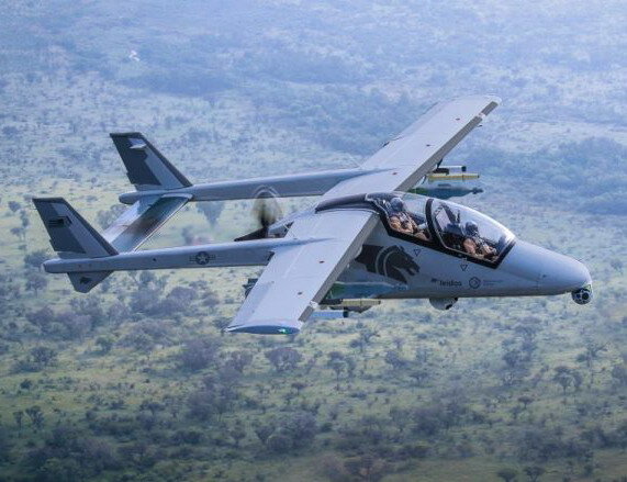
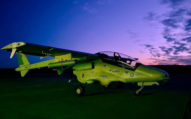
I saw this a few days ago in an AviationWeek article, this is a slightly belated report, but provides better info I think. It would be rather interesting if the Bronco II was successfull - imagine the USA buying a totally African designed and developed aircraft for their Airforce (or rather SOCOM)..!
I saw this a few days ago in an AviationWeek article, this is a slightly belated report, but provides better info I think. It would be rather interesting if the Bronco II was successfull - imagine the USA buying a totally African designed and developed aircraft for their Airforce (or rather SOCOM)..!
USAF is more likely to buy Bronco II, Tucano or Texan II to equip third world allies. Those allies only need to out-gun Al Quieda, Boko Haram, etc. Selling/giving low speed airplanes to allies means that the USAF will not be out-gunned when they need to re-invade their former ally.
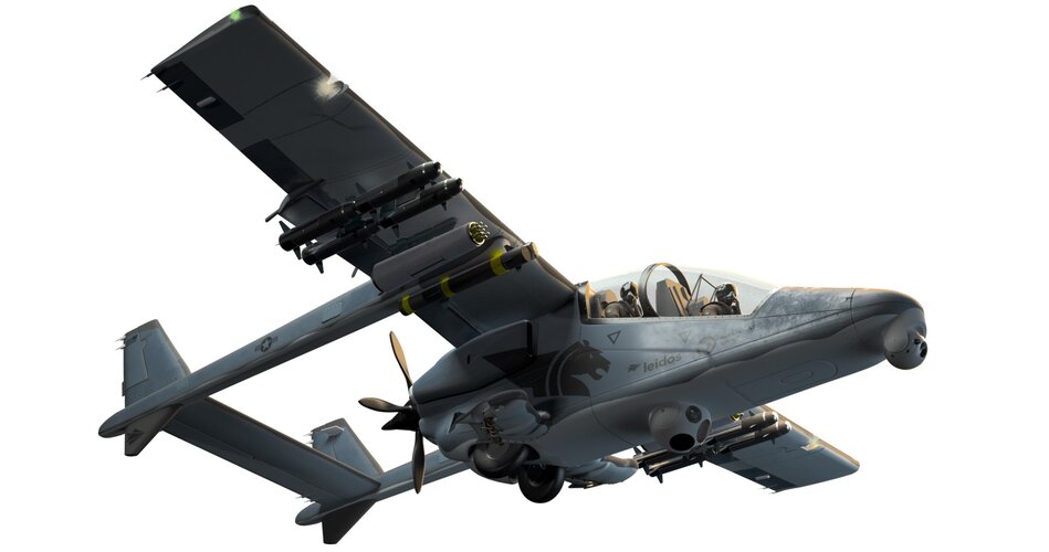
Many thanks for that Cluttonfred - here's a link to the team's (Leidos/Paramount/Vertex) well done website, which has some nice info, videos and pics on the Mwari/Bronco II.
Nice pic Kaiserbill (#258), however I suspect it's been 'Photo-shopped'.
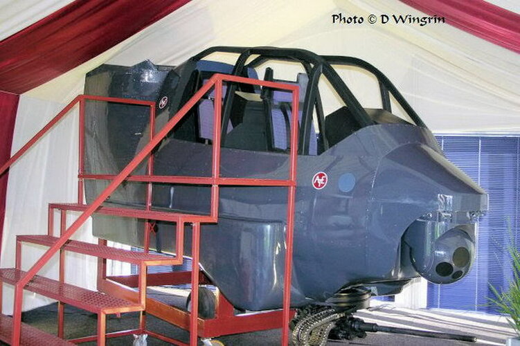
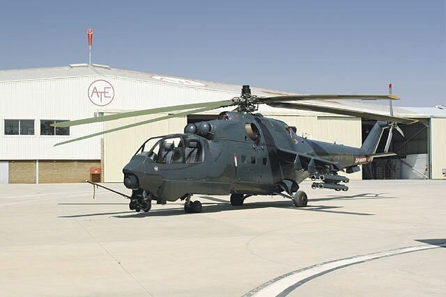
Here's an interesting one - I believe it's ATI's further or alternative development of the Super Hind cockpit (Mk IV ?), or it might just be their further development for the Rooivalk..? I suspect the former... (with acknowledgement and thanks to Dean Wingrin).
Nice pic Kaiserbill (#258), however I suspect it's been 'Photo-shopped'.
Here's an interesting one - I believe it's ATI's further or alternative development of the Super Hind cockpit (Mk IV ?), or it might just be their further development for the Rooivalk..? I suspect the former... (with acknowledgement and thanks to Dean Wingrin).
Another update on AHRLAC/Mwari - I'm getting a little tired of them as it just seems to be a regurgitation of the same old facts, however this sentence caught my eye "The AHRLAC/Mwari is currently being manufactured for several international customers at Paramount’s Wonderboom factory". Also there does seem to be some other additional info supplied..
One of the supplied pics (below), shows a version that looks subtlety different to the prototypes (installed sensors, antennae etc), could this be a production model?
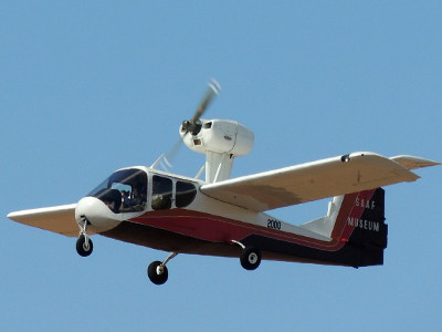
Here are a couple of pictures of the Patchen Explorer on display at AAD 2014. I thought the display panel for the aircraft had a lot of good info in it and was well worth posting.
A Patchen Explorer belonging to the South African Air Force (SAAF) Museum crashed near Air Force Base Swartkop this morning, killing two senior retired Air Force members. An eyewitness stated that the aircraft flew over his house “sputtering badly,” possibly from carb icing and went in short of...
Pretty much inevitable that this would dry up as a project (upgrade) - such a pity though... Some interesting comments about what they had in mind - and also regards the FZ 70mm laser guided missile/rocket tests...
Graugrun, I also sat up when I saw that pic. I thought it might have been one of the Carver wind tunnel models too.
Alas, it appears to be the Cheetah ACW wing with wingtip rails, as you mention. At least, I think it is...
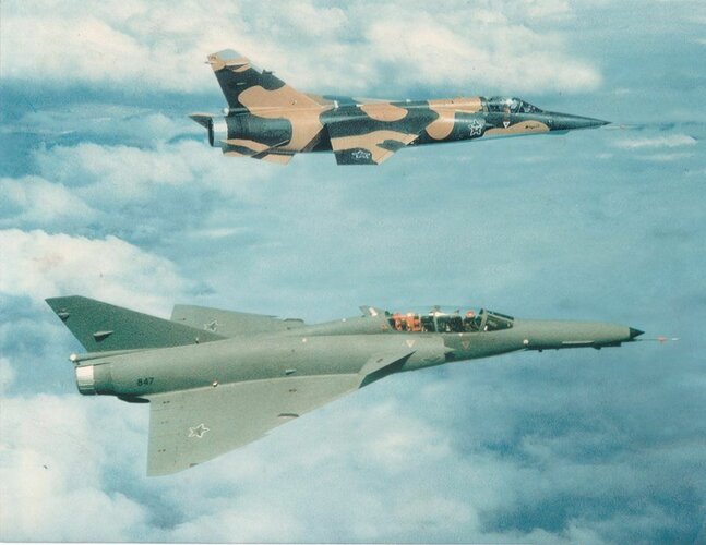
SA Bushwar, I wonder if if there were any windtunnel models of the original Super Mirage F1.
Basically, from what I can gather the plan was to upgrade the Mirage F1's once the Cheetah C's were in service. The upgrade was to mirror the avionics of the Cheetah C. When the cockpit and avionics suite was designed and selected for the Cheetah C, they deliberately designed and kept compatability with the Super Mirage F1 in mind, according to a fellow from the SAAF forum who worked on the project.
According to him, amidst other tweaks, the nose was to have been changed to a similar style to the Cheetah C as it would have had the same radar, and there was a bulge at the base of the verticle stabilizer, similar to the F-16 or Lavi, housing extra avionics.
All this was to basically ensure commonality across a fleet of upgraded F1's and Cheetahs pending the eventually introduction of Carver.
Interesting that the wind tunnel model doesn't have the fuselage extension plug. I suspect that the bulged spine was probably consideredas a possible relocation for the EW equipment, because I very much doubt there would have been interest in the Cheetah C for the SAAF without the EW capability. Here is a comparison with the wind tunnel model and a Cheetah C.
There have a fascinating and informative series of posts on SAAF projects on the Facebook group page "SWA/Angolan Border War 1966-1989". I see some of that info is already here but its well worth looking at. They have had a series of posts on ECM and chaff and flare protection for jet fighters, nuclear weapons delivery, and radar early warning systems among others.
Chaff and Flare & EW development. The Cheetah chaff/flare installation.
I was now at my new company, and we had a contract to design a chaff/flare dispenser installation on the Cheetahs which were being converted from Mirage IIIs to Cheetah at the time. The SAAF wanted one system that would fit all the different Cheetah models and they wanted even more cartridges on these aircraft than on the Mirage F1!
Our Mirage III fleet had various models, but only the Mirage III DZ, D2Z as well as the Mirage III E and Mirage III RZ and R2Z would be converted to Cheetah standard.
We did have quite a lot of Mirage III design data, but nothing on the aerodynamics. I had to think of a way to get one system to fit all and have the minimum impact on performance. I wanted to install the dispensers at the lower back of the aircraft as that would be best area for effective chaff/flare effectiveness and it is an area where the airflow is already not too smooth. I also had some photos of the Swiss Mirage IIIRS installation, but it did not even carry ½ of the number of cartridges the SAAF wanted. We began by looking at each of our Mirage III variants. Some models had a bombing camera in the fairing at the back of the lower aft fuel tank. Some had an arrester hook at the back of the same tank. On some models the fuel tank could be removed and replaced with a special tank that had a rocket motor with special fuel for shorter runway performance or a very rapid climb capability for intercept missions.
I soon learned that the SAAF did not use the rocket motor tanks anymore. This tank with the rocket motor seemed to have the most space available at the back which we could modify. We had flight data of our Mirage IIIs with this tank/motor installed and the impact on drag was minimal.
This gave us the idea that if we could design a chaff/flare dispenser that would fit within that profile, it would not have a detrimental impact on handling and performance of the aircraft without us having to find the aero data.
By using the same cartridge holders that were designed for the Mirage F1 ventral fin, we managed to fit the required number of cartridges into the rocket motor space in the lower aft fuel tank. We then designed a modification for the lower aft fuel tanks of the models that did not have the rocket motor tank by just copying the profile of our first design. We now had a design that carried the required number of cartridges, in a modified aft tank that had the same, known, aero impact as the rocket motor and the mod would fit all the Cheetah models at Atlas.
We modified and instrumented a prototype Cheetah and waited anxiously for the TFDC guys to give us the flight test results.
It worked perfectly and the whole fleet was modified.
Chaff and Flare & EW development. (Continued)
Since the SAAF was not too happy with the Mirage F1 performance with the Station 0 Chaff/Flare pylon, I was put in a very awkward position. A senior SAAF officer had previously asked me, unofficially, to work on an alternative design since I had doubts about the pylon design.
During a later heated meeting, where the flight test results of the station 0 design were being discussed, he asked me to present my alternate design proposal. There was a stunned silence in the room, and I knew my career might be on the line.
I first need to give some background that led to this alternate design:
The Mirage F1 has two ventral fins under the aft fuselage. These were a design fix for a fin flutter failure experienced on the F1 prototype. The vertical fin was reduced in size & the two ventral fins were added for directional stability during high aoa turns. These fins were mounted via 2 high tolerance pins that were bolted into the machined fuselage frames that carried the vertical fin’s loads into the fuselage. The ventral fins were constructed of machined frames and riveted skins. They were placed under the fuselage as dictated my aero requirements, but this also put them in an area which is subject the very high sonic loads leading to metal fatigue.
The screeching sound of a fighter passing overhead consists mainly of the hot supersonic air from the exhaust, forcibly mixing with cold atmospheric air. This causes high frequency sonic vibration and any harmonics to the natural frequency of metallic structure nearby is amplified in attachments between structures. The result of this was that the ventral fins started cracking.
We developed repair schemes, but the SAAF tasked Atlas to come up with a long-term solution. In my team were two very bright young engineers, one a graduate from Cranfield in the UK and the other an ex- Witsie with a MSc in carbon fibre structures. The latter technology was very new in aviation at the time. I asked them to design a new ventral fin. This was an official project with funding etc. It turned out to be more complex than anticipated since the sonic loads were difficult to measure during flight tests and we did not have enough knowledge about fatigue resistance in carbon fibre structures.
I had a meeting with them one afternoon and the problem kept recurring in my head. At about this time I was unofficially asked to do an alternate design on the chaff/flare issue. While listening to Bob Dylan while tinkering with a Formula Vee in my garage, the sound of his harmonica suddenly gave me an idea. If we could combine the design of the new ventral fins with long narrow rows of chaff/flare cartridges, we might just have a solution. The following week the guys started layouts and we could nearly fit the required number of cartridges in a ventral fin that has the same area as the original fin.
The new ventral fin and the cartridges would be quite a bit heavier than the original one, so we had to add an additional mounting point to each fin. This changed the natural frequency of the fin and it appeared from first calculations, that we would then avoid the harmonics that caused the metal fatigue in the first place.
So now we had a metal fin, slightly wider but with the same area as the original and it could carry nearly the number of cartridges the SAAF wanted. The only problem was that the electronics guys would have to redesign their cartridge holder and its printed circuit board.
So, when I presented this at the meeting, the big brass quickly asked how long it would take to build a prototype. The electronics guys were not happy, but we were already building 2 experimental ventral fins.
Not to long after the meeting, we had an aircraft fitted with the new ventral fins and instrumented for flight testing.
The increase in drag was so low, we could not measure it! The electronic guys came up with a very good plastic injection moulded casing and the cartridges fired perfectly from it.
The sonic fatigue problems also seemed to be resolved with the new ventral fins.
A contract was issued, and the fleet was fitted with the new ventral fins.
Of course, my boss was not impressed with my ‘gekonkel’ behind his back, and I knew I had to leave Atlas.
At this time, I was also finalising the Cheetah R2Z prototype and the SAAF asked if we could add a new chaff/flare installation on it that would carry more cartridges than the planned system.
Soon after the Cheetah R2Z completed it successful flight tests, I was advised by someone in the SAAF to consider moving to a small company in Pretoria that did special projects for the SAAF.
I went for an interview, got hired and we received the contract to design the chaff/flare system that would fit all the different Cheetah models.
At the time of the writing of this original document 2 x 6 Kt devices were already available and in fact already deemed obsolete, given the progress in R&D. And it was the view of the SADF that a minimum of 14 nuclear payloads would be required, some of the warheads being interchangeable between launch weapons. A total of 3 warheads were required for the HUSKY ballistic missiles.
Furthermore one HAMERKOP weapons system which was a fair weather guided glide bomb with a 20 kiloton TNT equivalent warhead was also available for use. 5 more were scheduled to be available by October 1987 to be used on the Buccaneer,Mirage Fl and the Cheetah aircraft.
At the time of writing, HUSKY, the all-weather medium-range ballistic missile had already been successfully tested overseas. And (Project OSTRA) the missile's nuclear payload development was already underway.
CS PLAN/302/6/DUNHILL dd 2 September 1987
Lieut.-Gen. F.E.C.v den Berg
pp CHIEF OF THE SA DEFENCE FORCE: GENERAL
"2. The approved strategy for the use of the KRAMAT capability as approved by the Minister of Defence on 24 November 1986 may be summed up as follows:
a. During the stage of strategic uncertainty the existence of a KRAMAT capability will be denied.
b. During the stage of covert negotiation the KRAMAT capability will be revealed as a means of inducement, persuasion and coercion.
c. During the overt deterrent stage the following actions will be considered:
i. Overt announcement.
ii. Display of force.
iii. Demonstration (underground or atmospheric test detonation).
iv. Threaten to use.
v. Use on battlefield as DETERRENT against conventional assault
forces.
vi. No strategic application foreseen, merely the threat of use."
Our Mirages were threatened and the SAAF had a few lucky escapes. Rynier Keet’s Mirage III was hit by a SAM-7, luckily not destroying the aircraft and he was brave and lucky to coax it over friendly territory and make an emergency landing.
The team was working hard to equip the Mirages with the same system as the Impalas. Fitting something like this to a supersonic aircraft is a much bigger challenge than the Impala.
The wings on these aircraft are thin and very sensitive to any additions to their external shape. So, to comply with the system requirements wrt view angles of the various antennae, we had to place the two forward looking quadrant antennae forward and on the side of the fuselage. Unfortunately, the vortices emanating form them under certain flight conditions could disturb the airflow and shockwave at the engine air intakes. It took a lot of calculations and other tricks to get a balance between aero and EW requirements to get them in place.
The two aft antennae were even more challenging. The EW guys wanted them up in the tail fin. However, due to the limitation of the length of the co-axial cables between the antenna and its amplifier, as set by the electronics, we also had to install the heavy amplifier high up in the fin. The combination of the air breaking away behind the antenna and the added mass high up in the fin was a big concern for us.
The Mirage F1 prototype crashed and killed the pilot during an early test flight due to fin flutter. Flutter is a phenomenon that high-speed aircraft suffer from. It is similar to a flag behind a flagpole that never flies straight, it always oscillates as the wind has small changes in direction. That is why the flag flaps back and forth. On high-speed aircraft, the onset of flutter is very rapid, and can result in the fin disintegration instantaneously. The rule for designers to reduce the risk of flutter is the avoid aero anomalies at the back of the fin and keep the mass of the structure as low as possible. The EW requirements were exactly the opposite!
We had to negotiate an extension to cable lengths with the electronics guys and this resulted in hot meetings and lots of comments by people who had no idea about aircraft design.
We ended up with a design that we felt could work if we did the flight testing very carefully.
The Chaff/Flare dispenser discussions did not go too well. Somewhere higher up than me, it was decided that the existing large dispensers as used in the Impala had to be used. I presented alternative designs, but these were rejected since nobody wanted to redesign the dispenser housing.
An outside group was tasked to design a special pylon that would fit under the wing of the Mirage F1 on a new wing station. I was horrified that the were going to drill holes in the lower skin of a supersonic aircraft! They also ignored a very important design principle of supersonic aircraft, the ‘area rule’ which is what gives these planes the beautiful Coke Bottle shaped fuselages. Our aerodynamicists calculated that the drag of the pylons would be quite detrimental to the aircraft’s performance, even in the subsonic range.
I took my objections to a senior officer in the Air Force, and he asked me to work on a parallel design in case our predictions were proven to be accurate. This was a bit of a problem, since I would have to use my team to work on an unauthorised project with no funds and against my boss’s instructions.
The prototype was modified and ready for flight tests. The antennae and EW system worked very well’
Then it was time to check out the dispenser pylons.
The Flight tests were a bit of a disaster. The aircraft performance was just as bad as my guys predicted and the brass was not impressed. There were a few very agitated meetings and presentations. At one such meeting, the senior officer asked me if I had an alternative design. The room went quiet, and I was on the hook! My boss looked angry and confused.
I had no choice and presented our design that was done by stretching my stationery and tea/cookie budget.
Chaff and Flare & EW development.(continued)
Development work proceeded diligently on the electronic system and in parallel we were working on the installation design, analysing the aerodynamic effects of placing the antennae where the systems guys prescribed to facilitate the best coverage and sensitivity of the antennae.
The first photo shows the system components: …
See more
As the threats against our aircraft escalated, the SAAF put tremendous pressure on the South African industry to find solutions that would protect our pilots and aircraft.
It must also be said that EW (Electronic Warfare) and self-defence systems against these threats are among the most strictly guarded technology in any country’s arsenal. The arms embargo meant that we were very vulnerable.
An electronics group started working on comprehensive solutions. For obvious reasons, I am not going to give technical nor corporate details. My job was to help the electronics guys to get their products to tolerate military aviation conditions and to guide the Atlas team that would design the installation of the various components on our aircraft.
A member of this group, Geoff Zeiler worked for this electronics group and if he chooses to, could help where my memory fails me. Bruce Gudgeon, also on this group, flew some of these aircraft and could also point to gaps in my recollections if he chooses to.
Some very clever innovation and long hours resulted in a Radar Warning System that basically consisted of 4 antennae that would ‘listen’ in four quadrants around the aircraft and alert the pilot if his aircraft was ‘illuminated’ by radar. The system would also warn him if a radar-guided missile was launched against his aircraft. The system could then eject chaff that was fired from cartridges similar to shotgun shells. The chaff was basically short strands of fine fiberglass covered by an aluminium coating. This cloud of chaff would ‘blind’ the radar seeker and with some manoeuvring, the pilot could break the missiles’ lock on the aircraft.
There were also some flare dispensers, which would fire burning chemical flares which emitted a more intense IR signal than the aircraft’s exhaust. The principle is that the flare moves through the missile’s field of view, and it would lock onto the flare, rather than the aircraft's exhaust plume. Since IR missiles track the aircraft without giving a detectable signal, the pilot did not have a means of knowing he is being followed. The flares were ejected at planned stages of the mission where it was most likely that IR missiles would be used.
These chaff and flare dispensers were initially designed to be attached to the pylons that are used to carry weapons under the wings. However, it was important to carry these dispensers in all configurations and especially on a ‘clean’ aircraft.
It was decided to install the system on the Impala first, as we had all the design data for it, since Atlas was manufacturing the Impala.
The installation design was complicated, and its requirements were definitely not aircraft friendly. Especially so for the dispensers which caused a lot of drag and vibration in the airframe.
And its Kobus De Villiers again. This guy is a goldmine!
Some more stories of our work for the SAAF during the SWA/Angolan war. This started long before the Russian engine project. In fact, in the late 70,s we already had our hands full!
Chaff and Flare & EW development.
In the beginning of the Bush war, our aircraft could operate relatively freely above the border. Over time, the Cubans and Soviets started supplying the enemy with more and more sophisticated ground-to-air weapons. We learned that especially the shoulder launched man-portable SAM-7 was proliferating and were available to most enemy foot patrols.
At the time I was a junior design engineer at Atlas and my boss, a real Irishman with lots of design experience at Short Brothers, called me in and tasked me to come up with a simple static system that could defend our Impalas from shoulder launched SAM-7 missiles.
We had ways and means to find some scarce information and I started looking at the passive systems that were developed by the US Air Force for their F-104 and the Israelis on their A-4 Skyhawks. See attached photos.
These shrouds just shielded the engine exhaust at such angles that the aircraft would be too far away before the SAM-7 to lock on. I designed a duct that would be fitted to the tailcone of the Impala. I added some internal flaps that would draw could air through the duct so that it would reduce the IR ‘footprint’ of the exhaust pipe and also change the visibility angle from the ground, so that the SAM-7 would be out of range before it could ‘see’ the IR emission from the engine exhaust.
We were still at the experimental stage of the design when we learned that the new SAM-7 had a much improved ‘ Infra Red eye’. Our tests on the duct design also showed that it had some negative effects on the Impala’s handling.
At this stage a South African company was developing some systems to protect our aircraft. As an aeronautical structural engineer, I was allocated to the team, since they were mostly electronic engineers and were not familiar with the limitations and requirements for the installation and carriage of such systems on aircraft.
Follow- up to Kobus post about EW ..In 1978 on course at Waterkloof, Air Defence school..Get guided tour of either 2 or 3 Squadron..Peering in cockpit, one of our guys sitting in seat, one of the pilots showing us the dials and knobs..The guy sitting in seat had been on Harvards, and knew his way around a cockpit, saw a small dial , tucked away..Asked pilot what it is, pilot seemed nervous, then confirming if we had Top Sec clearance, said it was new anti- radar/ missile device..Showed us the rear of aircraft, where a gadget, size of pack of 30 cigarettes was mounted, either above or below tailpipe..Explained that it picked up direction of threat, and whether above or below.
just above the tailpipe mounted on the dragchute housing. It interacted with a amplifier via a very finicky waveguide. You can see the waveguide running along the drag chute housing.
I see some of the guys think we just walked into the Mig factory and got working. If only it was so easy.
Once the project got approved, I had to select a team of 6 to 10 experts in each field that would be needed. This group then underwent a rigorous security and personality scrutiny. Then we had to decide what technical info we would need there and this had to be edited so that we did not give away any of our and other friend’s technology.
Our families did not know where we would be and were only given a telephone number and mailbox in Pretoria in case of an emergency.
We travelled in small groups via methods and routes I will not discuss here. Eventually, we all ended up in Brezhnev’s 1960’s dacha. Here we lived, 2 to a room, ate and worked for 10 hours every day, often on weekends too. In the summer we could go out into the big garden, but in the winter it was -20C most of the time. The Russian team of experts arrived every day by old army bus. In those days there were very bad shortages of everything in Russia and people stood in line for hours to get basic food. I arranged with the kitchen staff that the Russians could eat two meals with us every day. It went a long way to build trust and camaraderie.
The engine team worked on the design and modification of the engine, the Mig gearbox guys worked on the new airframe gearboxes and the South Africans worked on the design of the airframe mods, the changes to the hydraulic, electrical, air-conditioning and fuel system. We also had to work with pilots to get the cockpit, engine controls and instrumentation sorted out. We also worked on the new tailcone which we wanted to work with the engine nozzle so that we could reduce base drag in the supersonic range. The biggest challenge was the new very fast intake requirements. The intakes have to control the shockwave while giving maximum airflow into the new engine.
Every two weeks a few of us, plus our guards, would fly to Stalingrad to visit the Klimov engine facility to compare notes and check progress. Then Aeroflot had a series of crashes, so it was decided that we would do the trip by train! 12 hours each way through snow and frozen lakes, something like Murder on the Orient Express!
Every 6 weeks we sent a few guys home for R&R, since we could not go out of our compound. It was hard & I had my work cut out to keep the guys from irritating each other and getting cabin fever.
There was also always a sense of danger and towards the end of the program, one of the Russian managers was found in his car, somewhere in Moscow, with 6 bullets in him.
The photos tell some of the technical side.
Designing the engine air intakes.
I left this part for last. We had most of the drawings and data of the Mirage F1, since the SAAF had a licence for it from Dassault when they were bought. We had most of the drawings and data of the Mirage III and of course, all the drawings and data for the Cheetah upgrade. What we did not have was wind tunnel data. Most of the aerodynamics needed for the project, our specialists from Atlas could calculate.
However, the biggest technical challenge for the Mig engine project was the supersonic engine intake design. Intakes for supersonic aircraft are designed by very clever people with lost of mathematics, thermodynamics, wind tunnels and a good helping of black magic.
Jet engines want high pressure inlet air evenly spread over the face of the engine. This can reasonably be achieved in subsonic flight. This relatively simple design can be seen on passenger jets. Supersonic fighters are an entirely different matter.
Intakes are either two-dimensional, like on the F-15 and Mig-29 where you have a box-like intake with straight sides and a ramp door inside to control the airflow and at supersonic flight, to keep the shockwave attached just at the lip of the intake. The other type is the 3-D intake with round or D-shaped intakes. This type of intake normally has some complex shaped device that moves in or out of the intake to control the flow and shockwave. For both types, if the shock goes into the engine it will stall, and it can be damaged. If you keep the shockwave unattached and too far outside the intake, it causes a lot of drag and the aircraft might not even go supersonic. The Mirages and Cheetah has D-shaped intakes with a ‘mouse’ that runs into or out of the intake and each mouse is driven by a very accurate electrical screwjack. But it was slow to move the mouse because of the accuracy required.
The next thing to consider is the interaction between the pilot and the thrust arm. The most important thing in aerial combat is Specific Excess Energy. It is proportional to the ratio of net motive forces compared to the weight of the plane and proportional to speed
The net motive force is found by calculating the engine's ability to move the aircraft after accounting for friction and other aerodynamic issues that slows the aircraft down.
In those days, the pilot with the higher Specific Excess Energy wins the fight. Jet engines need time to spool up after the pilot moves the thrust lever forward. In our case, the Atar had a ‘normal’ spool up time for engines of that era. The RD-33 and therefore the SMR-95, had a much faster spool up time and was very pilot friendly. It gives you the edge in a fight, but only if the intakes can match what the engine demands.
The challenge was to design a modified engine intake that would fit the existing intakes on the Cheetah D and Mirage F1, yet they had to manage the shockwave and provide the engine with the airflow which the Fuel Control Unit demanded, and at the very fast rate that the SMR-95 responded to pilot inputs.
This took some midnight oil, a very clever young South African engineer and an old and experienced intake designer from Mikoyan to solve the problem. In the end this two, plus a lot of input from the team, came up with a newly shaped mouse, which was also rammed fast and accurately, forward and aft by two precision hydraulic rams and the whole lot was controlled by a black box that catered for things like uneven movement between the mice, aircraft turn rates, fuel flow, thrust arm movement and safety settings for possible failures at high speed etc etc.
The pictures tell the story.
BTW the test pilots loved the response of the engine.
Modern fighter aircraft carry an amazing array of electronics for navigation, target acquisition and self defense. With the arrival of air-to-air missiles that can strike at aircraft from beyond visual range and very fast ground-to-air anti aircraft systems, it has become critical that you have the latest and most powerful EW and radar on board.
These systems must be continuously upgradeable and needs more and more electrical power and cooling.
The Cheetah D/D2 and E had the latest avionics at the time, but we had a limitation in cooling and electrical supply. During the Cheetah upgrade project, we had to add a big heat exchanger with an external scoop, which you can see on the upper aft part of the fuselage. These kinds of scoops cause drag and variable cooling capacity depending on flight conditions. We solved this problem during the new engine project with the engine inlet duct heat exchanger. Now we had to look at the electrical supply.
If you have limited supply, you need to switch between users (beurtkrag!), but during air combat you want all the power you can get so that you can search for threats, lock onto the enemy and use your active EW to jam the bogey while all your weapons have unlimited access to power. For this you need lots of flexible electrical supply. On the older Mirages, we had 1 X 10kVA or 1 X 15kVA alternator and 1 X 15 Amp generator. The engine starter motor was built into the engine itself.
The SMR-95 engine needed an external starter, which could be reversed and used as a generator when the engine is running. The problem with big generators and alternators, is that they need lots of cooling and you are back to external scoops again!
Since the new engine was lighter and shorter than the Atar, we had a bit of space and mass in reserve which we wanted to use optimally.
The team came up with a plan that we develop new airframe gearboxes which would drive two of the latest 40 kVA Russian alternators, the starter motor, duplicate hydraulic, oil and fuel system pumps and the afterburner pump. This would be difficult but with the help of the Mikoyan gearbox boffins, the team came up with a very elegant design for the Cheetah as well as the Mirage F1.
The unique solution for the cooling of these monster 40kVA alternators was devised where we would have a cooling scoop that is open on the ground during start-up and taxi, but once the engine is spooled up and demands fuel, they were cooled by fuel on its way into the engine! The scoop can then be closed during flight.
It was a very tight fit, but the Russians built the prototype gearboxes, and we never had any failures or problems with them in more than 70 strenuous test flights and at any of the air shows where the aircraft performed after the test flights.
We had electricity to spare, no draggy scoops and flexibility for future upgrades.
The discussion about the Mig engine project seem to generate a lot of questions. One that is often repeated is: "Why were we working with old aircraft and old engines?"
The guys seem to forget that this took place circa 1990. The SAAF Cheetah D and D2s were delivered by Atlas from July 1986 to July 1988. The Cheetah E was delivered from March 1988 to April 1990. These were the latest frontline fighters we had and were equipped with the latest electronics, EW and in-flight refueling. The wings and other fatigue-critical parts were replaced and Canards fitted. These planes were essentially new and had a long life ahead of them. The only thing that was old, were the Atar engines.
At that time the best engines in that size were the G E F-404 (which powered the F-18), the M-88 (which powered the Rafale) and the RD-33 (which powered the Mig 29).
The GE F-404 first flew in the F-18 in 1978. The RD-33 first flew in the Mig 29 in 1981. In Fact, the Gripen that the SAAF has now, is powered by the Volvo RM-12, which is a GE F-404 built in Sweden under licence!
So, at the time this was very good technology to get exposed to and it would have powered our highly upgraded Cheetahs perfectly.
With this in mind, I can explain what we did with these engines. The modified RD-33, now called SMR-95, was shorter and much lighter than the Atar 09K50. We asked the Klimov guys to put the attachment points on the SMR-95 in such a wat that we could bolt it onto the same front attachments as the old Atar. These attachment were placed in such a way that the CG of the aircraft with the new engine and gearbox would be in exactly the same place as before. This gave us the freedom that we did not have to change the flight controls or fuel usage sequence. The pilot would also just have to be trained on the new engine controls and instrumentation, the aircraft handling would be the same.
Since the new engine was shorter than the old one by 750mm, we had to add an extension the the intake duct between the airframe and the engine face.
We also wanted to optimize the a/c performance more than just the gain from the engine thrust, so we looked at ways to reduce inlet scoops and bleed air for the air-conditioning of the avionics. The guys came up with the brilliant idea of designing this inlet duct extension into a heat exchanger! This save a lot of drag and engine bleed air loss. The photos attached explains it a bit.
This site uses cookies to help personalise content, tailor your experience and to keep you logged in if you register.
By continuing to use this site, you are consenting to our use of cookies.