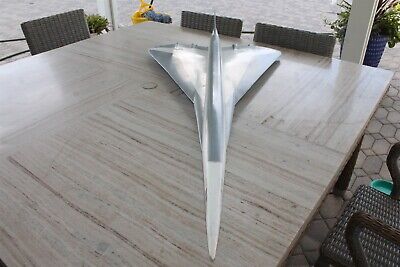
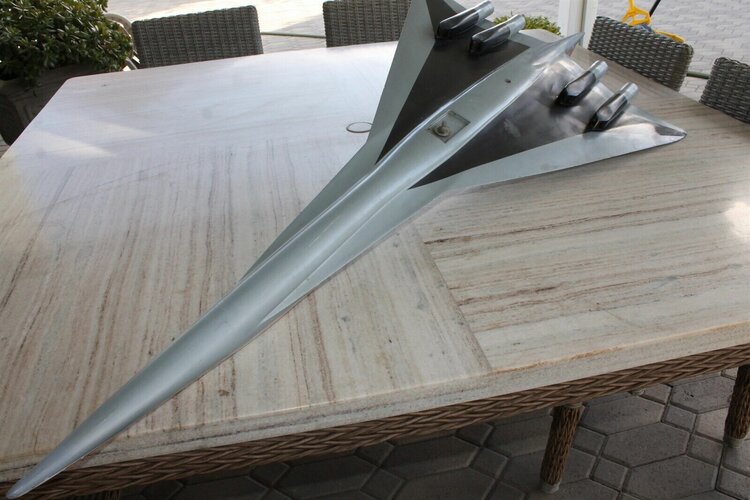
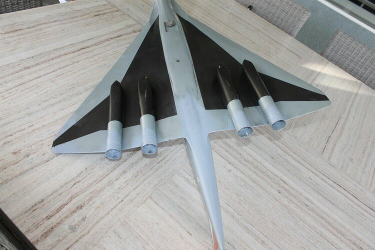
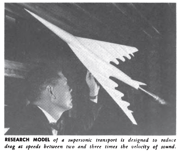
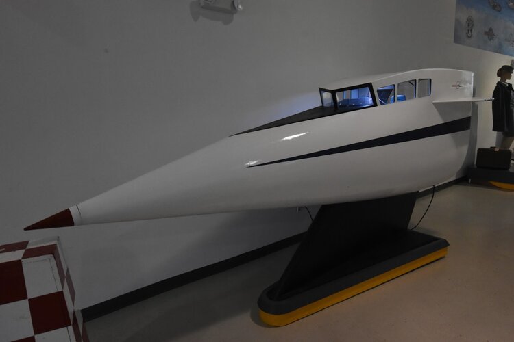
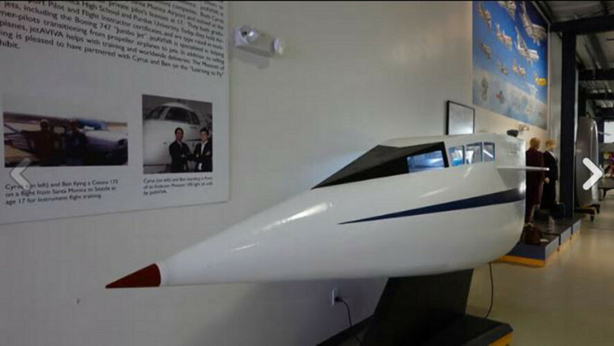
This is the SCAT-15F: The ultimate SST, and best looking, IMO.Rare 1960's NASA Aerodynamics SST Model
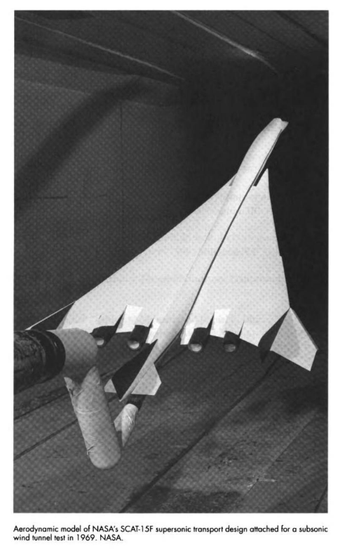
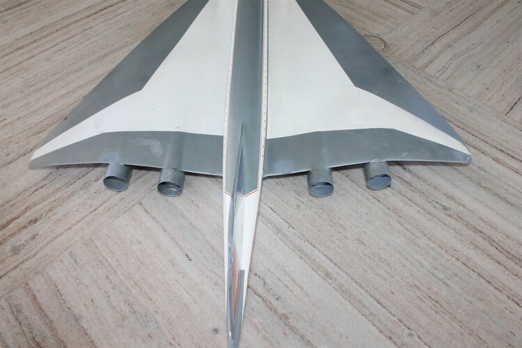
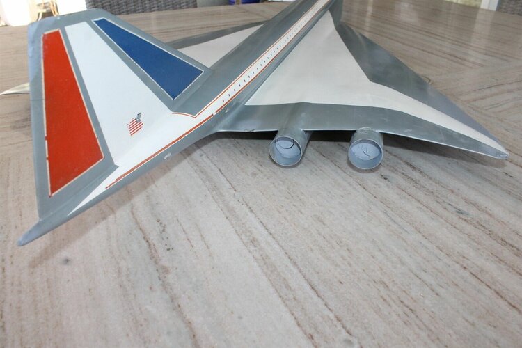
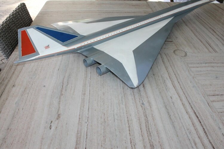
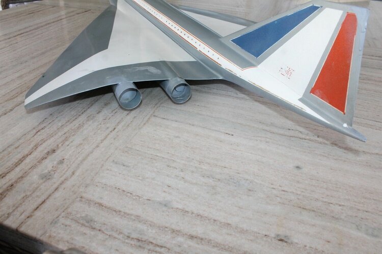
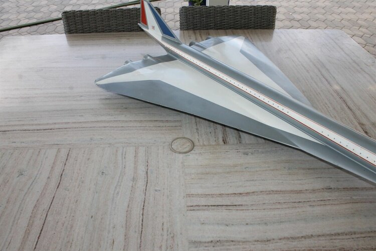
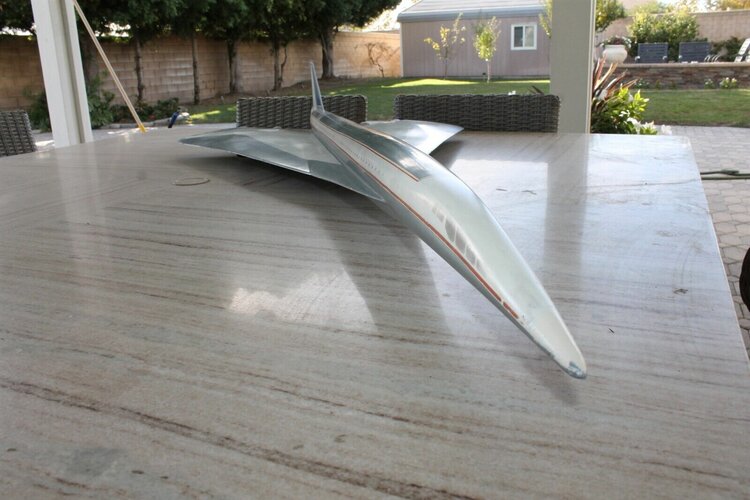
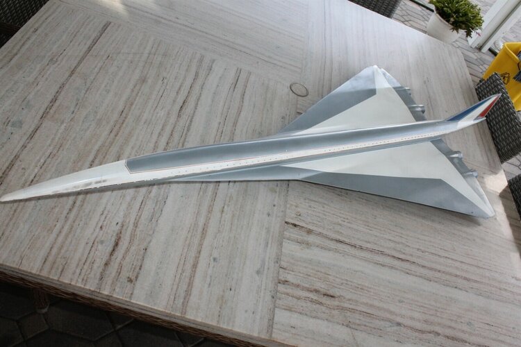
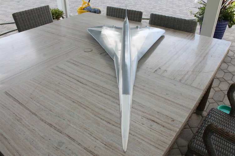
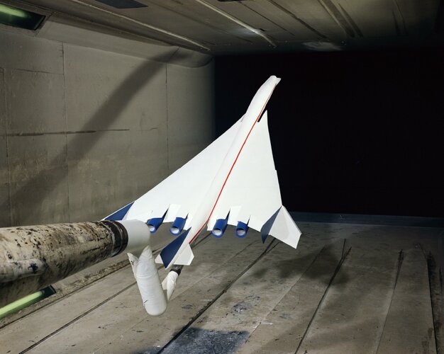
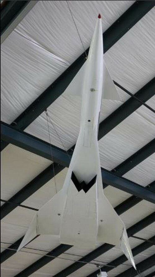
We recently acquired a rare 1960's aerodynamic test model for a NASA SST (Super Sonic Transport) vehicle from Langley Research Center. This model is rather large and is built of wood and composite materials. One rear fin has the NASA logo -- finish and condition is original. The piece measures 51" L and has a max width of 24". Everything is in tact with the minor exception of one rear fin. Wear has some dings and chip paint in areas. These Langley Aerodynamic models are very rare and as you can imagine and these were used in what is called the free-flight technique where they are tethered and float in the wind tunnel for study. A variety of designs were tested and this is one in the spectrum of craft. Reference the video for a demonstration of this type of craft in free flight testing. These video segments are courtesy of NASA Langley Research Center.
View attachment 669586View attachment 669587View attachment 669588
View attachment 669599
View attachment 669589View attachment 669590View attachment 669591View attachment 669592View attachment 669593View attachment 669594View attachment 669595View attachment 669596View attachment 669597View attachment 669598
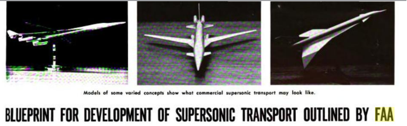
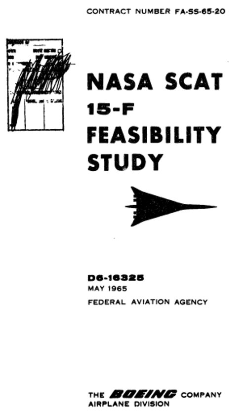
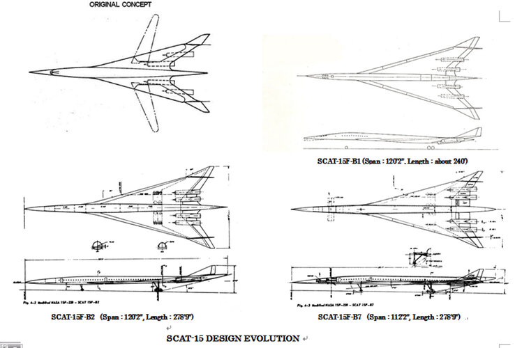
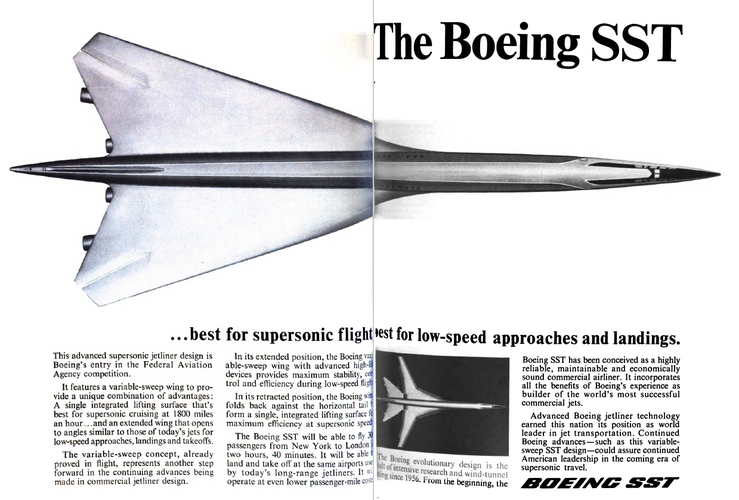
"…In 1964, advances in the sophistication of aerodynamic theory and computer codes at Langley allowed a team of Harry Carlson, Ed McLean, Warner Robins, Roy Harris, and Wilbur Middleton to design an improved SCAT configuration, called the SCAT-15F. This fixed-wing version of the earlier variable-sweep SCAT-15 configuration was designed using the latest, computer-based supersonic design methodology that Langley had developed, resulting in a L/D ratio of 9.3 at Mach 2.6, an amazing 25 to 30 percent better than the previous state of the art at that time. The new Langley theories permitted the researchers to shape the wing with reflex, twist, camber, and other parameters that nearly optimized its supersonic capability. When informed by the design team of the SCAT-15F’s projected performance, Larry Loftin (Langley’s top manager for aeronautics) did not believe the prediction. Subsequent wind tunnel results, however, proved the estimates accurate and the SCAT-15F remains to this day one of the most aerodynamically efficient SST designs ever conceived. Carlson, McLean, Robins, Harris, and Middleton were awarded a patent for the SCAT-15F design in 1967." -NASA archives
Last edited: