
You are using an out of date browser. It may not display this or other websites correctly.
You should upgrade or use an alternative browser.
You should upgrade or use an alternative browser.
US Lifting Bodies Studies - START (ASSET/PRIME), FDL, X-24, etc.
- Thread starter Archibald
- Start date
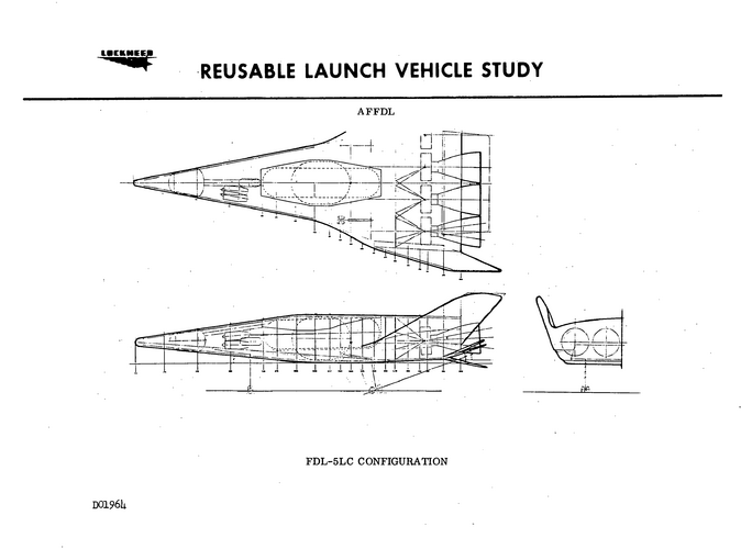
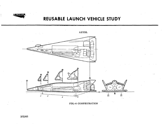
Orbiters from Lockheed's Reusable Launch Vehicles Study based on the FDL-5LC and FDL-8 shapes. From Executive Review Alternate Space Shuttle Concepts Orientation Meeting NTRS 19730064707_1973064707
Attachments
- Joined
- 6 August 2007
- Messages
- 3,011
- Reaction score
- 2,308
For those interested in the X-24C, from "America’s First Rocket Company: Reaction Motors, Inc." (https://arc.aiaa.org/doi/book/10.2514/4.104428) :
"However, William “Bill”/“Billy” Arnold, who joined RMI in 1946 and for years had been the company’s field service representative, made the cogent point that the usage of XLR-11 engines in NASA’s lifting bodies up to 1975 (covered in Chapter 5) was technically RMD’s final project. Beyond this, Arnold worked on the proposed, though never realized, lifting body followup, the X-24C program. He added that the XLR engines still bore the Reaction Motors name and he was still considered the Reaction Motors field representative, receiving paychecks from Thiokol up to 1976. He therefore contended that he was the last Reaction Motors employee, even though he was paid by Thiokol past the end of their Reaction Motors Division in 1972.
Arnold also worked at Edwards Air Force on a little-known related project until 1979 that incorporated both the XLR-11—using LOX and liquid ammonia as the propellants—and the XLR-99 toward the next step in piloted aircraft later called the National Aerospace Plane (NASP). The next step involved potentially exploring flight from Mach 5 up to Mach 10. For this exploratory work, however, Thiokol’s Elkton, Maryland, plant sold all the rights to these engines for $10,000 to Aerojet—and Arnold then worked for Aerojet."
Orbiters from Lockheed's Reusable Launch Vehicles Study based on the FDL-5LC and FDL-8 shapes. From Executive Review Alternate Space Shuttle Concepts Orientation Meeting NTRS 19730064707_1973064707
Your NTRS link is screwed up...
Last edited:
Paul czysz was my professor at parks college in the early 90’sSource: AIAA 2004-5888
An Essential Element in Affordable Space Access is the Return Vehicle. A Historical Perspective Based on Support Vehicles
for the Manned Orbiting Laboratory, circa 1964
Paul A. Czysz
HyperTech Concepts LLC, St. Louis, Missouri 63141, U.S.A.
Claudio Bruno.
University of Rome,<LA SAPENZA> Rome Italy
Ying-Ming Lee
MSE Technology Application, Butte, Montana. U.S.A.
Space 2004 Conference and Exhibit
28 - 30 September 2004, San Diego, California
Photo shows the array of delta planform configurations that the Flight Dynamics Laboratory had considered in the 1958 to 1968 time
period. Specifically identified on the photo are:
Configuration 2 was a higher wing loading, relatively blunt all body with an upswept spatular nose that is not
unlike the BOR series of Lozino-Lozinski hypersonic gliders from Russia. Because of the longitudinal extent of the
former USSR compared to the USA, the minimum lift-to-drag ratio to assure a landing on the continental USSR
land mass. The USSR requirement is for an L/D of about 1.7, whereas for the USA it is about 2.7. Thus, the lower
lift-to-drag ratio minimizes the possibility for a Russian spacecraft to land in the continental United States without a
long waiting period.
Configuration 3 was a subscale research vehicle to evaluate the thermodynamics and materials for hypersonic
gliders. The nose and leading edge radii were full-scale size of the X-20. ASSET was successfully flown on a Thor
IRBM booster. One that was recovered from its landing in the ocean was for a time on display in the USAF Museum
in Dayton, Ohio.
Configuration 4 was a product of cooperation between the Flight Dynamics Laboratory (Alfred Draper) and
McDonnell Douglas Astronautics Company, St. Louis (Robert Masek) to develop a vehicle to support the Manned
Orbiting Laboratory (MOL). This concept was briefed to the US Air Force in 1964. The variable geometry
switchblade wing permitted landing with heavy loads returning from space, and could eventually permit horizontal
takeoff. The tail configuration was an experimentally determined configuration feature. This configuration was
wind tunnel tested and demonstrated inherent stability and control over the speed range from Mach 22 to landing
speed. Paul Czysz was at the Flight Dynamics Laboratory from 1956 to 1963 and at McDonnell from 1963
onwards witnessed these configurations being developed.
Configuration 6 was a product of the Flight Dynamics Laboratory (Richard D. Neumann) to reduce the drag
of hypersonic gliders. Based on the physics that a two-dimensional wedge has less drag the a right circular cone of
the same volume, Neumann devised the “spatular leading edge”.
It is essentially a Spatular nosed version of Configuration 5. John (Jack) Pike of the RAE and Cranfield Technical Institute developed analogous configurations independently and published the wind tunnel and analytical work in 1973. Robert Krieger of McDonnell Douglas Astronautics, St. Louis also developed a Newtonian analysis of spatular noses8. The wind-body configuration was
the basis of the X-20.
Configuration 7 and the other lifting body configurations were FDL-7C/D class of configurations with a partial
horizontal surface and a vertical control surface. Without the “X” type tail configurations of the FDL-7C/D the
control capability was reduced and the usable lift-to-drag ratio was less. But nevertheless proved instrumental in
developing the FDL high lift-to-drag ratio configurations.
Configuration 8 is a FDL version of the NASA Langley HL-10 hypersonic glider.
Configuration 9 is a model of the Ames/Eggers M2/F2 half-cone derived configuration.
Configuration 10 is an adaptation of the Russian “Star Body” concept that The limitation is the configuration
concept is severely volume limited and had a high ratio of wetted (surface) area per planform area. This is an
adaptation of that concept to the FDL class delta gliders to evaluate the controllability provided by the star configuration.
In the process of adapting the star body configuration to the FDL delta configuration, the ability to have an
independent entry orientation was lost.
Configuration 1 is the X-24B or its AFFDL counterpart the FDL-8. It represents the different approach to hypersonic glider configurations by NASA and AFFDL. Martin Marietta built the X-24A at its Denver, Colorado facilities. The X-24A is a round fuselage configuration with outboard high dihedral angle vertical tails typical of the Ames Eggers vehicles and the Langley HL-19. All the configurations of this type have serious lateraldirectional stability problems at low speeds and tend to roll about the horizontal axis. One designer who solved the problem with variable dihedral vertical tails (+60 to –10 degrees) was Gleb Lozino-Lozinski of Russia. The Flight Dynamics Laboratory solved the problem by using flat bottom configurations. Under a USAF Flight Dynamics Laboratory program, Martin modified the X-24A into flat-bottomed configuration with trailing edge elevons called the X-24B. Bill Dana was the NASA pilot that flew the X-15, X-24A and X-24B. His comments about the change in slow speed performance with the X-24B confirmed the advantage of the Flight Dynamics Laboratory approach. The basis of the X-24B was the FDL-8 configuration.
Trying to wrap my mind around the four FDL shapes: FDL-5, FDL-6, FDL-7 and FDL-8.
So,
- FDL-5 went to Lockheed and resulted in the FDL-5MA proposal
- FDL-7 was Douglas baby, hence: Model 176
- FDL-8 went to Martin, they reworked NASA X-24A into the X-24B according to it
But what the heck was FDL-6, and did any aerospace giant drew rocketplane proposals around it ?
So,
- FDL-5 went to Lockheed and resulted in the FDL-5MA proposal
- FDL-7 was Douglas baby, hence: Model 176
- FDL-8 went to Martin, they reworked NASA X-24A into the X-24B according to it
But what the heck was FDL-6, and did any aerospace giant drew rocketplane proposals around it ?
martinbayer
ACCESS: Top Secret
- Joined
- 6 January 2009
- Messages
- 2,374
- Reaction score
- 2,100
For what it's worth:Trying to wrap my mind around the four FDL shapes: FDL-5, FDL-6, FDL-7 and FDL-8.
So,
- FDL-5 went to Lockheed and resulted in the FDL-5MA proposal
- FDL-7 was Douglas baby, hence: Model 176
- FDL-8 went to Martin, they reworked NASA X-24A into the X-24B according to it
But what the heck was FDL-6, and did any aerospace giant drew rocketplane proposals around it ?
https://forum.ipmsusa3.org/topic/17439-nasas-fdl-6/
FDL-6 classified Sub-Orbital Maneuver Vehicule. Now you see it !
Now you see it ! The classified FDL-6 SOMV from the AFFDL Air Force Flight Research Laboratory (now known as AFRL) was an hypersonic high-lift-to-drag ratio lifting body which was developed in the 1960s and early 70s at the same time as the better known Lockheed FDL-5 and MDD FDL-7 hypersonic air...
Noooo ! As much as I love the model and respect its maker, just - no. Short story: it is the one and only thing that cames out of freakkin' Google when doing any "FDL-6" search.
Not that it is @martinbayer fault, btw.

Not that it is @martinbayer fault, btw.

martinbayer
ACCESS: Top Secret
- Joined
- 6 January 2009
- Messages
- 2,374
- Reaction score
- 2,100
Back to basics then - see the upper center configuration in the top picture at https://www.rocketryforum.com/threads/us-hypersonic-lifting-bodies-1956-1966.163955/ and ignore the rest ") .
.
.In addition to Martin's offering:Noooo ! As much as I love the model and respect its maker, just - no. Short story: it is the one and only thing that cames out of freakkin' Google when doing any "FDL-6" search.
from AFFDL-TR-71-2 'Experimental Test Results and Comparisons with Simple Theory for the FDL-6C Configuration at Subsonic Mach Numbers' (attached)

Let's hear it for low quality reproduction methods:

Attachments
Seems DTIC has 5 tech reports related to Lockheed FDL-5A proposal, 1966-69 ? sorry if they have aready been posted elsewhere. Now they are safe at NASAspaceflight (I hate to say that, but they can host larger files. Whatever.)
 forum.nasaspaceflight.com
Lifting Body Air and Spacecraft Q & A
Lifting Body Air and Spacecraft Q & A
forum.nasaspaceflight.com
Last edited:
- Joined
- 2 January 2006
- Messages
- 977
- Reaction score
- 1,657
Ford Aeronutronic EMPIRE. RV. design, 1962 ... https://www.wired.com/2013/01/ford-aeronutronic-empire-1962/
Attachments
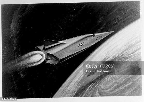
Hypersonic Concept for Entry Vehicles
(Original Caption) This artist's rendering illustrates the advanced hypersonic concept in entry vehicles achieved by Lockhead-California (sic) Company Engineers. The Fuselage is uniquely contoured to provide aerodynamic control in both high and low speed regimes. The design breakthrough eliminates the outer fins, which means that a smaller surface area is exposed to high temperature as the hypersonic craft flies back through the atmosphere and returns to earth for landing.
This artist's rendering illustrates the advanced hypersonic concept...
This artist's rendering illustrates the advanced hypersonic concept in entry vehicles achieved by Lockhead-California Company Engineers. The Fuselage is uniquely contoured to provide aerodynamic...
www.gettyimages.co.uk
I realize I’m a few years late to this conversation, but I was at Scaled when we built the X-38 drop test vehicles. We asked the same kind of questions. Apparently their configuration scoring system rated the volumetric efficiency and resulting lower orbital mass of the X-24A configuration very highly. This along with the world’s largest parafoil they decided was needed to land it caused endless eye rolling.Amazing after all those flights ending with X-24B which demonstrated sharper nose flat bottom planform was far superior to the blunt bodies with vertical winglets. FDL-7 planform series incorporated these design attributes. So what does NASA and mainstream aerospace do? They ignore all that and to this day NASA is still generating blunt designs? Did a generation of engineers forget the lessons of the past?
I realize I’m a few years late to this conversation, but I was at Scaled when we built the X-38 drop test vehicles. We asked the same kind of questions. Apparently their configuration scoring system rated the volumetric efficiency and resulting lower orbital mass of the X-24A configuration very highly. This along with the world’s largest parafoil they decided was needed to land it caused endless eye rolling.
Not surprising, first they wanted to carry a lot of astronaut and cargo to the space station, because Shuttle. In a more subtle way, my understanding is that the FDL-7 outstanding crossrange (it was expressly designed to get the absolute best crossrange) may have been overkill for ISS. I have trouble explaining that in english (not a born speaker) but the FDL-7 was designed to be able to land on CONUS whatever the orbit and time. This needed a terrific crossrange that dictated the shape. Much better explained in the attached paper, well worth a read.
NASA however had learned to wait for the orbits to align for a CONUS landing, even if it took a few hours or part of a day. Except in the very specific case of a dying astronaut, they could wait in orbit a little, to catch a CONUS landing strip.
Attachments
Last edited:
lostcosmonauts
ACCESS: Confidential
- Joined
- 8 March 2020
- Messages
- 102
- Reaction score
- 150
Relevant model from Sotheby’s current Space Exploration auction
Some nice Soviet models in there as another lot
Some nice Soviet models in there as another lot
The parafoil was due to the requirement not to have a pilot onboard for emergency departure. Volumetric efficiency was needed to return cargo and crew.I realize I’m a few years late to this conversation, but I was at Scaled when we built the X-38 drop test vehicles. We asked the same kind of questions. Apparently their configuration scoring system rated the volumetric efficiency and resulting lower orbital mass of the X-24A configuration very highly. This along with the world’s largest parafoil they decided was needed to land it caused endless eye rolling.
- Joined
- 1 April 2006
- Messages
- 10,730
- Reaction score
- 6,760
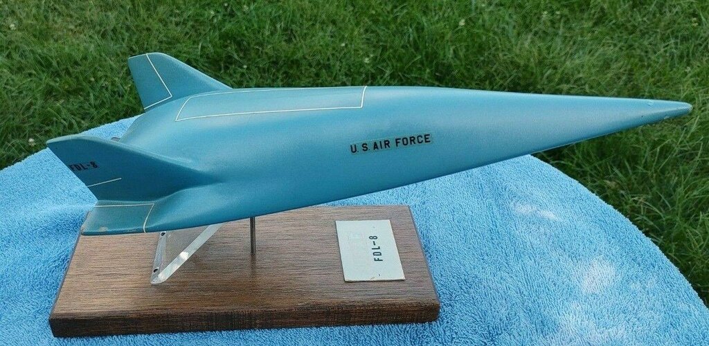
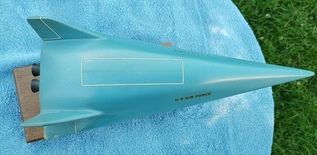
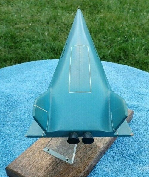
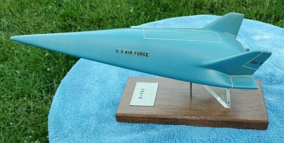
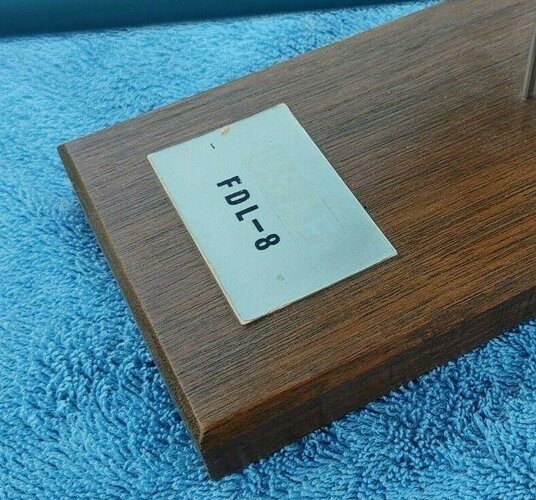
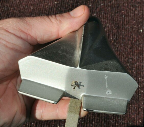
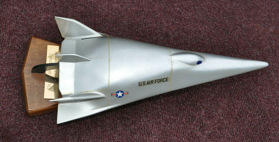
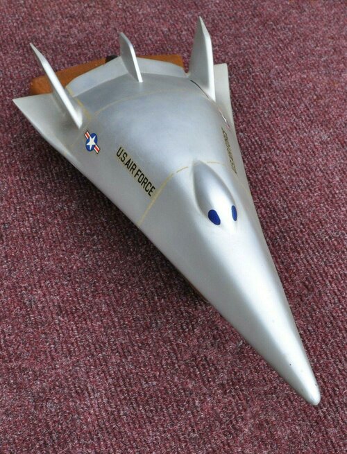
Hypersonic porotype desk model FDL 8 Air Force Wright Flight Dynamics Laborator | #3873083396
Out of the office of Wright Pat employee estate sale 14 inches long 5 1/2 widevintage Hypersonic porotype desk model FDL 8 Hypersonic porotype desk model FDL 8 Air Force Wright Flight Dynamics Laborat
 www.worthpoint.com
Attachments
-
 1_62e8f8535297bb06edac5cb2e35c6929.jpg238.2 KB · Views: 76
 -
 1_62e8f8535297bb06edac5cb2e35c6929 (1).jpg252.1 KB · Views: 66
 -
 1_62e8f8535297bb06edac5cb2e35c6929 (2).jpg121.5 KB · Views: 63
 -
 1_62e8f8535297bb06edac5cb2e35c6929 (3).jpg168.9 KB · Views: 59
 -
 1_62e8f8535297bb06edac5cb2e35c6929 (5).jpg221.3 KB · Views: 56
 -
 1_62e8f8535297bb06edac5cb2e35c6929 (4).jpg154.9 KB · Views: 64
- Joined
- 29 July 2009
- Messages
- 1,529
- Reaction score
- 1,548
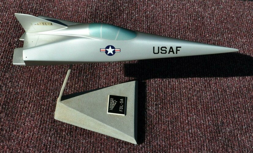
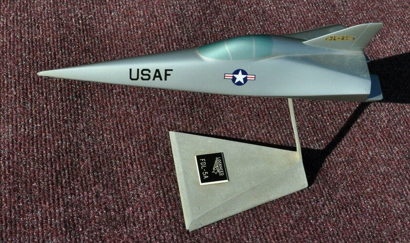
Same site as above: FDL-5L-A (same, but nicer condition of model in post #348)
 www.worthpoint.com
*** RARE Vintage Desk Model Lockheed FDL-5L - A Spacecraft *** | #3873007077
THIS AUCTION IS FOR A RARE EXECUTIVE DESK MODEL. THE MODEL IS A FDL-5L-A BY LOCKHEED. THIS JUST CAME OUT OF AN ESTATE FROM AN EMPLOYEE THAT WORKED AT WRIGHT PATTERSON AIR FORCE BASE. I BOUGHT THIS MOD
www.worthpoint.com
Attachments
Last edited:
- Joined
- 29 July 2009
- Messages
- 1,529
- Reaction score
- 1,548
*** RARE Vintage Desk Model Lockheed FDL-5A Spacecraft *** | #3871408203
THIS AUCTION IS FOR A RARE EXECUTIVE DESK MODEL. THE MODEL IS A FDL-5A SPACECRAFT BY LOCKHEED - CALIFORNIA CO.. THIS JUST CAME OUT OF AN ESTATE FROM AN EMPLOYEE THAT WORKED AT WRIGHT PATTERSON AIR FOR
www.worthpoint.com
Attachments
archipeppe
ACCESS: Top Secret
- Joined
- 18 October 2007
- Messages
- 2,291
- Reaction score
- 2,340
Awesome models!
The last one resemble more the rumored X-24C rather the original FDL-5A.....
The last one resemble more the rumored X-24C rather the original FDL-5A.....
Fairly sure this is FDL-8X (FDL-8 > X-24B transition)Awesome models!
The last one resemble more the rumored X-24C rather the original FDL-5A.....
Last edited:
- Joined
- 29 July 2009
- Messages
- 1,529
- Reaction score
- 1,548
- Joined
- 6 August 2007
- Messages
- 3,011
- Reaction score
- 2,308
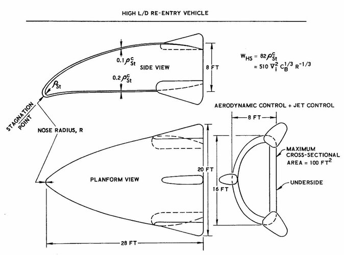
"PRELIMINARY DESIGN AND EXPERIMENTAL INVESTIGATION OF THE FDL-5A UNMANNED HIGH L/D SPACECRAFT: Part I Summary", AFFDL-TR-68-24 Part I, 1968
"PRELIMINARY DESIGN AND EXPERIMENTAL INVESTIGATION OF THE FDL-5A UNMANNED HIGH L/D SPACECRAFT: Part IV - Aerothermodynamics", AFFDL-TR-68-24, PART IV, 1968
"PRELIMINARY DESIGN AND EXPERIMENTAL INVESTIGATION OF THE FDL-5A UNMANNED HIGH L/D SPACECRAFT: Part IV - Aerothermodynamics", AFFDL-TR-68-24, PART IV, 1968
I didn't see this DIA document earlier in the thread. Much of this is from Paul Czysz's presentation material. Includes some additional charts and diagrams I believe.
I meant to ask, do we have a thread with more information on the MDC "squat/recoverable" booster concept shown in this?
Thanks
Randy
"PRELIMINARY DESIGN AND EXPERIMENTAL INVESTIGATION OF THE FDL-5A UNMANNED HIGH L/D SPACECRAFT: Part I Summary", AFFDL-TR-68-24 Part I, 1968
"PRELIMINARY DESIGN AND EXPERIMENTAL INVESTIGATION OF THE FDL-5A UNMANNED HIGH L/D SPACECRAFT: Part IV - Aerothermodynamics", AFFDL-TR-68-24, PART IV, 1968
Seems DTIC has 5 tech reports related to Lockheed FDL-5A proposal, 1966-69 ? sorry if they have aready been posted elsewhere. Now they are safe at NASAspaceflight (I hate to say that, but they can host larger files. Whatever.)
Lifting Body Air and Spacecraft Q & A
Lifting Body Air and Spacecraft Q & A


- Joined
- 13 August 2007
- Messages
- 7,149
- Reaction score
- 6,522


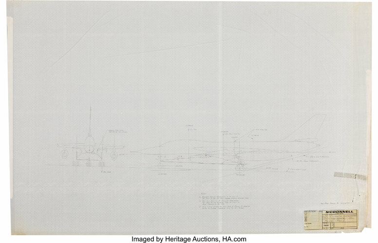
Where's that from? Were the "dots" on the original, or is that some sort of digital watermark?B-58 Launched Mach 3 McDonnell 'Low Speed Manned Test Vehicle' concept from 1965:
Just watch for Dr. Zaius on return
martinbayer
ACCESS: Top Secret
- Joined
- 6 January 2009
- Messages
- 2,374
- Reaction score
- 2,100
A winged ballistic capsule sounds just a little bit like a winged aerostat airship, because of unnecessary mass induced by functional redundancy.
Last edited:
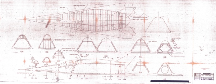
It's from a listing which was part of Heritage Auction's 2020 November 21 - 22 Space Exploration Signature Auction - DallasWhere's that from? Were the "dots" on the original, or is that some sort of digital watermark?
Gemini: Rare Vintage McDonnell Gemini Re-entry Vehicle Blueprint,with Additional McDonnell Concept Blueprint.
It looks like it's on the original piece, not an artefact) but I'm not sure what it is exactly (tracing?) - note the title block has been cut out (from the original?)- Joined
- 1 April 2006
- Messages
- 10,730
- Reaction score
- 6,760
Where's that from? Were the "dots" on the original, or is that some sort of digital watermark?
Attachments
Thanks. That's an odd feature to be sure. Dots might be simple watermarks that darkened over the decades.It's from a listing which was part of Heritage Auction's 2020 November 21 - 22 Space Exploration Signature Auction - Dallas
Gemini: Rare Vintage McDonnell Gemini Re-entry Vehicle Blueprint,with Additional McDonnell Concept Blueprint.
It looks like it's on the original piece, not an artefact) but I'm not sure what it is exactly (tracing?) - note the title block has been cut out (from the original?)
Could be, but the accompanying Gemini blueprint does not exhibit the same effect. The cut-out title block from the 'concept' blueprint is the same media as the Gemini blueprint, I presume.Could be from an overlay between the light source and the vellum (this is backlit.) El Cheapo analog watermarking.
edit: Could it be that the 'concept' print is on tracing paper and what we are seeing is some king of perforated bed using a low vacuum to hold documents flat while they are being shot (which is of course usually hidden by opake media)?
It does rather look like perforated metal sheet overlaid with thin vellum paper, often what was originally drawn on for use in making cyanotype and similar process blueprints. That would explain the relative transparency of the paper; the "grating" is less obviously useful, unless it was, as suggested, some sort of vacuum table (nothing else seems to have used it) or just what happened to be available for photography.


Last edited:
A winged ballistic capsule sounds just a little bit like a winged aerostat airship, because of unnecessary mass induced by functional redundancy.
Concept was to meet an Air Force (note the "star-n-bars" and lettering on the hatch
) cross-range request. Not really sure that ever got a really good 'concept' for the idea but the general idea was to reenter with the nose and lifting surfaces rather than the capsule style reentry.Randy
Similar threads
-
 Secret Flight Test History - An Alternate History of the X-24C
- Started by Dynoman
- Replies: 26
-
-

-
-
 USAF interplanetary spacecraft concept using SPUR
- Started by Triton
- Replies: 15