I stumbled across this brillant idea and wonder why it hadn't been thought of sooner …

You are using an out of date browser. It may not display this or other websites correctly.
You should upgrade or use an alternative browser.
You should upgrade or use an alternative browser.
Propeller design reinvented
- Thread starter Dirk_Vau
- Start date
Intresting, but the concept itself is not entierly new:
View: https://www.youtube.com/watch?v=MNnB_50Z20I&ab_channel=BoatTEST.com
View: https://www.youtube.com/watch?v=QNCbnntCU2k&ab_channel=SharrowMarine
Noise reduction will become very important for larger vessels, maybe we will see bigger versions for ships in the near future. I would also be intrested to know if this works well with a variable pitch.
Noise reduction will become very important for larger vessels, maybe we will see bigger versions for ships in the near future. I would also be intrested to know if this works well with a variable pitch.
Last edited:
Volkodav
I really should change my personal text
- Joined
- 28 March 2014
- Messages
- 652
- Reaction score
- 1,088
And what is really interesting is the USN has just contracted an Australian company to secure their leading edge 3D printing technology, including the likely ability to 3D print submarine propellers.
See fig. 3:
 www.wearefinn.com
Another publication by GKN Aerospace, the inventor of the boxprop propeller:
https://publications.lib.chalmers.se/records/fulltext/208320/local_208320.pdf
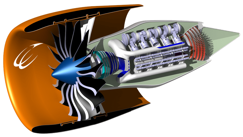
Are major efficiency gains for the turbofan still in reach?
The EU Horizon 2020 ULTIMATE project is looking at ‘radical engine concepts’ to significantly reduce engine C02 and noise emissions by 2050. The project's researchers explain more.
www.wearefinn.com
Another publication by GKN Aerospace, the inventor of the boxprop propeller:
https://publications.lib.chalmers.se/records/fulltext/208320/local_208320.pdf
Last edited:
What I find especially intresting is the turbocompound drive in this project, see also:See fig. 3:
Are major efficiency gains for the turbofan still in reach?
The EU Horizon 2020 ULTIMATE project is looking at ‘radical engine concepts’ to significantly reduce engine C02 and noise emissions by 2050. The project's researchers explain more.
Similar?
 techxplore.com
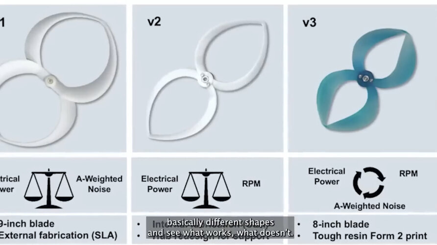
Propeller advance paves way for quiet, efficient electric aviation
Electrification is seen as having an important role to play in the fossil-free aviation of tomorrow. But electric aviation is battling a trade-off dilemma: the more energy-efficient an electric aircraft is, the noisier it gets. Now, researchers at Chalmers University of Technology, Sweden, have...
- Joined
- 11 March 2012
- Messages
- 3,016
- Reaction score
- 2,697
May I suggest a toroidal biplane racer?
The top wing would look like an exageration of the (currently popular) Schumann planform with wing tips curving down to meet the bottom wing.
The bottom wing would be a reverse Schumann planform to capture vortices shed by the top wing and channel those vortices towards wing root. The bottom leading edge would be a complex, curved forward sweep with even more forward sweep in the curved trailing edge.
Forget about making this in wood and fabric.
To derive all of the aerodynamic benefits, you would need to 3D mill female molds, then lay up composite (perhaps graphite) skins within the molds.
Hint: Greg Catto (of propeller fame) had already built composite wings for several Formula One racers that competed at Reno.
- Joined
- 2 August 2006
- Messages
- 3,175
- Reaction score
- 1,159
The problem you can run into in that case is the down wash from the forward higher wing changes the local alpha of the bottom wing, greatly reducing it's efficiency.May I suggest a toroidal biplane racer?
The top wing would look like an exageration of the (currently popular) Schumann planform with wing tips curving down to meet the bottom wing.
The bottom wing would be a reverse Schumann planform to capture vortices shed by the top wing and channel those vortices towards wing root. The bottom leading edge would be a complex, curved forward sweep with even more forward sweep in the curved trailing edge.
Forget about making this in wood and fabric.
To derive all of the aerodynamic benefits, you would need to 3D mill female molds, then lay up composite (perhaps graphite) skins within the molds.
Hint: Greg Catto (of propeller fame) had already built composite wings for several Formula One racers that competed at Reno.
The zipdrone here has unusual double propellors on the same side:
View: https://m.youtube.com/watch?v=DOWDNBu9DkU&embeds_euri=https%3A%2F%2Fup-ship.com%2F&feature=emb_logo
I don’t know if that would scale up well…they look less like partially open scissors.
As a counter-weight…I might have the loop type propellor opposite the scissor type…perhaps given a twist to play with vortices a bit? How odd it might be that the perfect prop-design looks like the breast cancer ribbon loop:

That drone’s cloud-car might replace fast-roping if it scales up well.
I don’t know if that would scale up well…they look less like partially open scissors.
As a counter-weight…I might have the loop type propellor opposite the scissor type…perhaps given a twist to play with vortices a bit? How odd it might be that the perfect prop-design looks like the breast cancer ribbon loop:
Giant Awareness Loop - Golden Openings
goldenopenings.com
That drone’s cloud-car might replace fast-roping if it scales up well.
Last edited:
- Joined
- 11 March 2012
- Messages
- 3,016
- Reaction score
- 2,697
We are hoping that trapping wing tip vortices will provide a greater advantage than the loss due to biplane interference. The other issue is positioning the top and bottom wings far enough apart both vertically and staggered to minimize interference. Vertical spacing should be more than 1.5 chords. Horizontal staggering would displace top and bottom wing roots more than 1 chord.The problem you can run into in that case is the down wash from the forward higher wing changes the local alpha of the bottom wing, greatly reducing it's efficiency.May I suggest a toroidal biplane racer?
The top wing would look like an exageration of the (currently popular) Schumann planform with wing tips curving down to meet the bottom wing.
The bottom wing would be a reverse Schumann planform to capture vortices shed by the top wing and channel those vortices towards wing root. The bottom leading edge would be a complex, curved forward sweep with even more forward sweep in the curved trailing edge.
Forget about making this in wood and fabric.
To derive all of the aerodynamic benefits, you would need to 3D mill female molds, then lay up composite (perhaps graphite) skins within the molds.
Hint: Greg Catto (of propeller fame) had already built composite wings for several Formula One racers that competed at Reno.
Finally, we hope that firmly attaching wing tips we will gain a structural advantage.
- Joined
- 19 July 2016
- Messages
- 3,729
- Reaction score
- 2,694
Any chance of a graphic example please?
Nik
ACCESS: Top Secret
- Joined
- 15 July 2009
- Messages
- 1,140
- Reaction score
- 810
Are we looking at the DeLanne formula problem ? IIRC, Germans tried to reverse-engineer it from his nimble prototype, but could not get it right. Seems they got dysergy instead of synergy for the wings' interactions, were not amused. Subtle 'counter-intuitive for that era' stuff, perhaps ? The UK's Lysander conversion, done with DeLanne's approval, worked as intended....
Well it seems to work for ships props...

 www.sharrowmarine.com
Sharrow Marine - The Propulsion Revolution is Here
The Sharrow Propeller™ offers a faster, quieter, and more fuel efficient ride through state-of-the-art design that is custom machined and fitted to every boat. Two-time award winner and the first major advancement in propeller technology since the 1830s.
I allready linked it in the second posting...Well it seems to work for ships props...
Sharrow Marine - The Propulsion Revolution is Here
The Sharrow Propeller™ offers a faster, quieter, and more fuel efficient ride through state-of-the-art design that is custom machined and fitted to every boat. Two-time award winner and the first major advancement in propeller technology since the 1830s.
Similar threads
-
-
 110mm T203 and 156mm T202 howitzers
- Started by A Tentative Fleet Plan
- Replies: 1
-
-

-
Anglo-US Crusader/Hammerhead Sea Mine
- Started by A Tentative Fleet Plan
- Replies: 15