History of the Flight
At 1345 Atlantic Daylight Time (All times are given in ADT), May 14, 1985, the Northrop F-20A prototype aircraft, GI-1001, United States of America civil registration N3986B, took off from Goose Bay Airport Runway 08 on a 5 min. practice demonstration flight in preparation for the Paris Air Show. The flight was the sixth demonstration flight flown that day on the aircraft and the fourth flown by the accident pilot The demonstration flight was to be centered at the midpoint of the runway and had been authorized by the appropriate Canadian authorities. The final maneuver sequence of the scheduled routine, which had been previously flown about 60 times by the pilot, called for a simulated head-on, low level, air to ground attack followed by a sharp 9g pull up at approximately 380 kt. This sequence was to be followed by level flight, left aileron rolls as necessary to provide adequate spacing from the runway, prior to entering a left downwind and base turn for landing.

Film taken of the mishap sequence shows that the aircraft entered an apparently normal right rolling pull up following the low level attack maneuver. The aircraft then completed 1 1/2 rolls to the left, then momentarily hesitated in the inverted position. The left roll was then continued as a barrel roll, which resulted in a descending roll out to a wings level attitude with about a 16 deg. nose low pitch attitude. The aircraft's heading was almost reciprocal to that required for the intended downwind and landing pattern. The landing gear was not extended. The aircraft continued descending, slightly increasing its nose down pitch attitude until it struck open, snow covered, fairly level terrain in an upright, slightly left wing low, nose down attitude. The aircraft was destroyed at impact, and the pilot sustained fatal injuries.

The mishap occurred less than 1 mi. north of the Goose Bay Airport Runway 08 at 53 deg. 19 min. N. Lat., 60 deg. 26 min. W. Long., at an elevation of 160 ft. above sea level. The accident occurred at 1349.

Injuries to Persons

The pilot, the only person on board, was fatally injured.

Damage to Aircraft

The aircraft was destroyed.

Other Damage

Damage was limited to ground scars in the vicinity of the accident.

Personnel Information


  • Age 40.
  • Pilot license--Airline Transport Pilot (USA).
  • Medical expiry date--Jan. 17, 1986.
  • Total flying time--5,240 hr.
  • Total on type--154 hr.
  • Total last 90 days--84 hr.
  • Total on type last 90 days--39 hr.
  • Hours on duty prior to occurrence--4 hr.
  • Hours off duty prior to work period--12 hr.
The pilot was qualified on the aircraft type and held valid licenses and ratings.
Prior to his employment with the Northrop Corp., the pilot had served 15 years with the United States Air Force. He resigned his regular commission in 1981 and joined Northrop in January, 1982, as an engineering test pilot and F-20 Tigershark flight test project and demonstration pilot. He retained his commission as a major in the USAF reserve and was a current pilot on the C-141 aircraft. His military flying experience was primarily on high performance jet aircraft such as the T-38, F-4, F-15 and F-111. He had flown 120 combat missions in Southeast Asia. Immediately prior to joining Northrop, he was an instructor test pilot at the USAF Test Pilot School.

His initial military aeromedical training was conducted during February, 1967. He received additional refresher training with USAF, the last of which was conducted on Mar. 22, 1984, at Edwards AFB. His F-5/T-38 egress and parachute descent training was completed June 6, 1984. His Stencel ejection system and egress training was completed Jan. 16, 1985. There was no evidence found to indicate that he had received formal g induced loss of consciousness (GLC) training, which includes the use of a centrifuge, or that he was cognizant of the proper methods of carrying out anti-g straining maneuvers, nor was any evidence found that such training was required prior to being selected for, or participating in, high g demonstration activities. A second demonstration pilot indicated that at the time of the accident he also was unaware of many aspects of the GLC phenomenon.

Aircraft Information


  • Manufacturer--Northrop Corp.
  • Type--Northrop F-20A Tigershark.
  • Year of manufacture--1983.
  • Serial number--GI-1001.
  • FAA Special Airworthiness Certificate-- Valid.
  • Total airframe time-- 4l0 hr.
  • Engine type--General Electric YF-404-GE-100
  • Maximum allowable takeoff weight-- 26,544 lb.
  • Recommended fuel types--Jet A l, JP 4, JP 5, JP 8.
The aircraft had been serviced and maintained in accordance with United States Federal Aviation Regulations pertaining to experimental aircraft. It was on flight number 400 since manufacture. The gross weight of the aircraft at takeoff was 16,500 lb., including 2,800 Ib. of fuel. Calculated weight at impact was 14,900 Ib. The aircraft configuration was established to provide a center of gravity just forward of the 25% Mean Aerodynamic Chord position for the air show sequence. The F-20 was flight tested in this configuration prior to the air show flights. The weight and center of gravity were within the Northrop designed limits.

The F-20 flight control system (FCS) consists of a conventional hydromechanical system augmented by an electrical control augmentation system (CAS). The hydromechanical position of the FCS consists of conventional mechanical inputs to dual hydraulic actuators. Full rudder deflection and 60% of horizontal tail authority are available from the hydromechanical system. The remainder of horizontal tail authority is provided by the CAS. On this aircraft, the CAS did not provide any control to the ailerons.

The CAS is controlled by a direct current powered flight control computer. The flight control computer provides power to and receives input signals from a digital air data unit, the aircraft rate and acceleration sensors, the control column and rudder pedal position sensors, and the cockpit control panels. The flight control computer processes inputs and sends signals to CAS actuators, which together with hydromechanical actuators, position the control surfaces.

A maintenance record review indicated that, during a practice demonstration flight on the previous day (Flight 394), the CAS PITCH 1 warning light illuminated, followed by the illumination of the PITCH 2 light during the final stages of the flight. These warnings indicated that the CAS had failed, but the subsequent landing was uneventful. The problem was traced to spillage of electrolyte from the main battery onto the flight control computer unit, which was located next to the battery. Rectification included cleaning and neutralizing the battery compartment, replacing the battery, taping the battery box and replacement of the flight control computer. The area was checked after each flight for further electrolyte leaks; none were found.

Meteorological Information

The weather sequence taken at the time of the mishap was sky conditions clear, visibility unrestricted, temperature 8C, dew point 4C, altimeter 30.02 in. Hg., wind 300 deg. true at 12 kt.

Communications

The aircraft was under the positive control of the Goose Bay tower; communications were on ultrahigh frequency (UHF) 236.6 MHz. To communicate with the aircraft, Northrop company personnel operated a very high frequency (VHF) mobile communications unit at the demonstration site. During the mishap flight, all transmissions to and from the aircraft were normal. No radio transmissions were made to or from the aircraft from commencement of the final maneuver to impact.

Airport Information

The Goose Bay Airport is situated on an inlet that forms part of the northeast coast of Labrador. The airport, which is operated by Transport Canada under a public license, has two runways constructed of concrete, with an asphalt overlay. Runway 16/34 is 6,200 ft. long by 200 ft. wide; Runway 08/26 is 11,050 ft. long by 200 ft. wide. The airport reference elevation is 160 ft. asl. The other demonstration pilot practicing the air show sequence reported that the horizon provided a good reference in the areas around the airport.

Flight Recorders

The aircraft was not equipped with a flight data recorder or cockpit voice recorder, nor was either required by regulation. During the flight test program, the aircraft had been equipped with a cockpit video recorder, but this equipment was removed during reconfiguration for the Paris air show. The nonvolatile memory of flight control computer components, which were recovered from the wreck age, provided data on the function of the flight control system from take-off to impact.

Wreckage and Impact Information

The aircraft struck the ground upright in a slightly left wing low, nose down attitude. The wreckage was spread over an area approximately 1,000 ft. in length and 100 ft. in width on a general heading of 065 deg. magnetic, 4,900 ft. north of Runway 08. The wreckage area was a gently undulating stream bed. The ground at the impact point was covered with melting snow to a maximum depth of 2 ft. Just beneath lay a sandy and slushy layer 4 6 in. deep on top of frozen strata 6 8 in. thick. A wet, firm sand lay underneath.

The aircraft penetrated the sandy, slushy area and rebounded into the air when it struck the frozen strata. The forward fuselage disintegrated upon initial impact and was destroyed.

The left and right wings were found in two sections left and right of the flight path, respectively. The leading edge flaps were broken loose from their attachment points and remained in the initial impact area. The left leading edge extension penetrated the frozen soil at an angle 20 30 deg. from the horizontal and was buried several feet deep in the initial impact crater, leaving only part of the spar attachment visible.

The aircraft center and aft fuselage continued down the extended flight path, further breaking up as it tumbled and contacted the ground. On the third contact, the engine broke free and separated from the aircraft. The engine was found adjacent to the vertical stabilizer, which came to rest in an upright position, 725 ft. from the initial impact point.

The remaining forward fuselage and nose landing gear came to rest furthest from the initial impact point. The ejection seat was tangled within the mass of wiring that constituted the forward fuselage and cockpit area. The landing gear selector panel indicated that the gear handle was in the up position at impact. There was no evidence of preimpact structural failure.

Medical and Pathological Information

Goose Bay is situated within the bounds of the Atlantic time zone, which is 4 hr. ahead of the time at the pilot's home base in California. The pilot departed from California on a scheduled commercial flight on May 10, 1985, four days prior to the accident. He ferried the F-20 from Andrews AFB, Md., to Goose Bay via Ottawa on May 12.

The accident pilot flew two of three planned air show practices on May 13, 1985. His first takeoff was at 1515, and he landed following the second flight at 1616. The third mission was cancelled because of the CAS problem experienced during Flight 394. In the evening, the accident pilot joined some Northrop personnel for dinner in a local restaurant. The pilot retired to his hotel room at 2230 and ate breakfast at 0730 prior to commencing flight duties on the day of the accident. He had completed two consecutive demonstration flights 2 hr. prior to the accident. His first takeoff that day was at 1115, and his second was at 1140. The pilot remained in the cockpit while aircraft refuelling took place between these two flights. This was a normal procedure used by both demonstration pilots.

The pilot landed from his second flight at 1145 and had rested and consumed a light snack before taking off at 1318 for the first of his final two consecutive flights; the contents of the light snack could not be determined. He landed at 1323 and again remained in the cockpit during refuelling. During the time on the ground, the pilot indicated in a humorous maintenance entry that he was thirsty. He took off at 1345 for his final flight, which terminated 4 min. later. The pilot's most recent U. S. Federal Aviation Administration medical examination was performed Jan. 18, 1985, by a company medical examiner. As a result of that examination, he was assessed as fit to FAA medical standards.

FAA Form 8500 8, completed immediately prior to the examination, required the pilot to declare all medical treatment received within the past five years and to certify, by signature, the truth and accuracy of such disclosure to the best of his knowledge.

Medical information gathered during the investigation established that the pilot had a history of, and received medical treatment for, ' achalasia" which was diagnosed in 1982. The pilot did not disclose this information on Form 8500 8. The pilot's supervisor was aware that the pilot had received treatment for achalasia, but he did not know that the company medical examiner was unaware of the treatment received.

Achalasia is the failure of the motor action of the lower part of the esophagus due to a deterioration of nerve function. It is an acquired neuromuscular disorder. Normally, solids and liquids are propelled down the esophagus by a wave like action, called peristalsis, which is under the control of the autonomic nerve system. In this disease, the peristaltic action stops at the affected segment of the lower part of the esophagus. This results in failure of relaxation of the functional sphincter between the esophagus and stomach during swallowing. The part of the esophagus above the lower affected segment becomes dilated, elongated and tortuous. Food can accumulate in the esophagus for some time before it passes into the stomach.

Some symptoms can include chest pains and general discomfort. Regurgitation and even vomiting can occur involuntarily during normal activities.

The probability of this reflux activity occurring would be increased substantially in flight and even more so during aerobatic maneuvers. A symptom associated with reflux activity is hypotension (low blood pressure).

The pilot had been treated by dilatation of the affected segment with a balloon device. He had had three such procedures, the first of which failed. Two were in 1983, the most recent in January, 1985, about 3 1/2 months prior to the accident. This procedure is usually at least temporarily successful. However, it occasionally leave permanent incompetence of the junction between the stomach and esophagus. More importantly, there can be reversion to relative closure of the lower end of the esophagus in two to three months.

Review of USAF annual physical examinations from 1980 to 1985 revealed no indication of pre-existing disease. It was noted, however, that several electrocardiograms (EKGs) reflected a sinus bradycardia (a relatively low heartbeat rate of 54 58 beats per min.), which USAF considered to be normal for an athletic individual.

The autopsy was not able to rule out or confirm the effect of achalasia on the pilot. There was no evidence of any pre-existing cardiac disease. Tests for drugs and alcohol were negative with the exception of caffeine.

Fire

There was no evidence of in-flight fire or visible smoke from the aircraft. The impact-induced explosion and fire was of short duration and was contained within the impact area.

Survival Aspects

Acceleration Forces


The acceleration forces sustained when the aircraft struck the ground exceeded human tolerances. The cockpit structure was destroyed, and the injuries sustained by the pilot caused immediate death.

Escape System

The aircraft was fitted with a parachute-equipped, rocket propelled Stencel ejection seat. The Stencel system provides the pilot with a safe escape capability from zero airspeed on the ground to an airspeed of 600 kt. at 50,000 ft. The ejection system has four operating modes.

For the final trajectory of the accident flight, the system would have been operating in mode 1 at the wings level position. In this mode, the parachute opens approximately 2 sec. after ejection initiation. Examination of the Stencel ejection seat and related escape system ballistic items indicated that 19 of the 24 ballistic items had not been fired and were still live. Actuation of the five ballistic items that did fire was the result of seat and aircraft break-up during the crash sequence.

The front lower portion of the ejection seat bucket, which contains the ejection handle, had completely broken away from the seat and had actuated the right hand ejection initiator. The cable that actuates the left hand and right hand ejection initiators is continuous from the left-hand initiator through the firing handle located at the forward center of the seat bucket to the right hand initiator.

The left hand initiator did not fire because its outer sheath was sheared on the left side of the seat at impact. Only the left hand initiator provides ballistic gas from the seat to the canopy jettison system. The canopy jettison thruster was found retracted with its firing pin still intact.

Tests and Research

Inspections, teardowns, tests and analyses were conducted by the Canadian Aviation Safety Board at the accident site and the CASB Engineering Branch; General Electric Corp., Lynn, Mass.; Hamilton Standard, Farmington, Conn., and Northrop Corp. Aircraft Div., Hawthorne, Calif. Tests and analyses performed by the manufacturer and contractors were monitored and reviewed by CASB investigators.

Engine

he engine was disassembled and examined to assess the engine power level at the time of impact and to determine if there was any engine related failure. Examination of the turbomachinery indicated significant fan damage, compressor damage and a large amount of debris visible through the basic engine, back to and through the outer bypass duct.

The low pressure turbine sustained mechanical damage to all blades, with the blade tips rolled over from impact with the turbine shroud. The engine damage sustained was consistent with an engine rotating at high rpm. at the time of impact.

The main fuel control and the afterburner fuel control systems were disassembled and examined. All valves and linkages of these controls were found free and undamaged. The main fuel control examination revealed marks that coincide with mating levers when the speed shaft is positioned to command a high engine rotation speed. The position of the valve in the afterburner hydraulic actuators indicated that the afterburner was operating at an engine thrust level between 15,350 and 16,300 Ib. at impact.

Measurements of the nozzle engine diameter on the film taken of the accident flight showed that the engine remained in the afterburner range.

On several frames of the film, the glow of the afterburner was observed.

Flight Controls

The flight control computer (FCC) was recovered and examined for possible battery electrolyte contamination. No evidence of electrolyte contamination to the FCC internal components or the external case was found.

wo nonvolatile memory (NVM) boards from the Right control electronics set (FCES) were recovered from the wreckage. The nonvolatile memory is designed to record and store data on in flight failure history of the FCES and to remain intact after essential 28 v. d. c. bus electrical power loss.

Although both boards were damaged, the NVM chips were removed and installed on serviceable test boards for memory read out. Both chips produced identical results implying that both FCC channels had been cleared by the pilot prior to flight and were functional with no fault codes recorded up to 0.2 sec. prior to the loss of electrical power, which would have occurred at impact.

A total of 11 flight control hydraulic actuators were recovered and examined: two pitch servos, two speedbrake actuators, two rudder servos, two aileron servos and three control augmentation system actuators. The examination did not reveal any evidence of pre impact unserviceability to any component. Evidence derived from the pitch servo impact capture marks was consistent with a horizontal stabilizer position of 2.25 deg. Ieading edge down at impact.

This position would be a nominal automatic pitch trim setting for the flight profile immediately prior to impact.

No evidence of foreign objects (FOD) was found during the wreckage investigation.

Analysis of the movie film taken of the final maneuver (maneuver 8) indicated correct aircraft response to all flight control movements recorded throughout the mishap sequence.

Flaps

The flap selector switch was normally selected to the auto position by the pilot during the demonstration flight profile. This selection automatically cycled the flap position to suit the changing aerodynamic requirements for the flaps during flight to provide optimum aircraft performance. The main flap mixer and travel limit units were recovered and examined. The cams of both units indicated that the flaps were at the three quarter position; i. e., 18 deg. Ieading edge down, 16 deg. trailing edge down. This setting equates to an automatic mode airspeed range of 200-300 kt.

Instruments

The primary attitude indicator from the aircraft's instrument panel was examined and found to have the off warning flag captured out of view as a result of the impact. The off flag derives its power source from the essential 28v. d. c. bus to power it out of view, indicating that the essential d. c. bus was powered to impact.

Examination of the shattered cathode ray tube (CRT) of the flight director and head up display (HUD) showed evidence of impact damage induced electrical high voltage arcing on the inner components of the tube, indicating that the a. c. bus was powered to impact.

No engine instrument data were recoverable because the instruments were liquid crystal displays.

Examination of the airspeed indicator showed an approximate impact speed of 250 kt.

Photogrammetric Information

During the demonstration practice, a company photographemrecorded the entire flight using 16 mm. movie film at 24 frames per sec.

The film, which contained footage of the mishap (flight number 400) and footage of other practice flights flown earlier in the day (flight numbers 395 to 399), was developed and examined. The film exhibited high quality images of the aircraft in all six of the flight demonstrations flown that day hlcluding the accident flight. Copies were made of the film in 16 mm. format and in l/2 in. video format for further study.

Arrangements were made with Northrop Corp. and with the USAF Aeronautical Systems Div. to carry our photogrammetric analysis of film footage of the aircraft during its final maneuver.

Analysis of the movie and of photographs of the crash site allowed a number of estimates to be made. These include the following: the amount of g force applied during the pull up; speeds at various points during the accident maneuver; construction of an accurate plot to include the camera location, and construction of an estimated ground track and final flight path .

Digital computer simulations were conducted to determine probable control inputs and the subsequent aircraft response to those inputs.

A frame by frame analysis was conducted of the total maneuver starting from the initiation of the simultaneous right turn and pull up (time zero) and continuing to the point of the last full view of the aircraft, before It passes behind the trees. The total duration for this maneuver to occur is 18.54 sec., and the first indication of fire above the trees is observed at 20.29 sec.

For maneuver number 8, the aircraft approached the camera traveling from right to left, at a speed of 361 kt. The camera was situated on the south side of Runway 08 and slightly west of the threshold. The aircraft was headhlg toward a simulated air show chalet position, situated approximately 2,000 ft. west of the Runway 08 threshold and 500 ft. south of the runway. This scenario was practiced on previous flights flown that day. As the aircraft reached the end of the runway, a right turn and a simultaneous 7.2g pull up were executed. The peak onset g level was 6.2g per sec., which was reached 1.0 sec. after the start of control application.

As a result of the right turn, the heading changed about 120-150 deg. relative to the original high speed approach heading. On completion of the pull up and right turn, the aircraft entered a left, full deflection aileron roll starting from a right wing low position, approximately 1,200 ft. agl. at a speed of 210 kt. The left rudder deflection is observed at the initiation of this left roll. The commanded left roll continues for approximately 1 l/2 rolls to essentially an inverted position as the aircraft proceeds away from the camera at a speed of 175 kt. The left roll had progressed slightly past the inverted position but was corrected back to the inverted. This inverted position (with the nose low) was maintained for about 0.9 sec. before a roll to the left was again initiated.

This stopping and starting of the roll appeared to be in response to appropriate movement of the ailerons. As the left roll continued, the aircraft was at a very nose low attitude. The nose had been raised substantially by the time the aircraft reached an upright, nose low wings level attitude, which was maintained for about 3 sec. until impact. Prior to reaching this wings level attitude, the horizontal stabilizer had been deflected, trailing edge up, by a substantial amount, possibly the full deflection of 20 deg. Just after the aircraft reached the wings level, nose low attitude, the horizontal stabilizer was observed to be deflected very little relative to an axis running through the fuselage from nose to tail. Immediately thereafter, the nose low attitude increased slightly, and the aircraft disappeared from view behind a line of trees.

During the final descent, and prior to disappearing from view, the aircraft accelerated to 258 kt. at a negative flight path angle of approximately 33 deg. and a pitch attitude of24 deg.; the angle of attack would have been 9 deg .

In an attempt to isolate any human abnormalities evident during the final maneuver of the mishap flight, all other final maneuvers flown on the same day were analyzed frameby frame. There were six flights flown that day, flights 395 to 400. The first two and last two were flown by the accident pilot. The middle two were flown by the other demonstration pilot. The maneuver entry airspeeds and speeds during the left rolls were calculated and compared as well as the roll rates and landing gear extensions. The pilots' throttle handling was also compared.

When compared with the other final maneuvers flown that day, significant differences were noted during the mishap maneuver: the stopping of the left roll in an inverted position, the lack of landing gear extension and failure to deselect the afterburner.

In addition, the aileron roll following the high g pull up and turn was not executed with authority and precision; it resembled a barrel roll, and it was not termhlated at the correct angular position As well, no significant elevator deflections or aircraft pitch attitude changes were observed during the final wings-level descent to impact.

Other Information

Life Support Equipment


The automatic pressure breathing oxygen regulator hose was examined. No pre impact abnormalities or evidence of deterioration was found. The pilot's oxygen mask was recovered in several pieces. The pieces were examined and analyzed by the Civil Aviation Medical Unit for possible contamination by food or stomach contents; none was found.

The pilot's USAF type anti g coverall was examined. The ''comfort zippers" were done up; all lacing in the abdomen, thigh and calf areas was done up, with loose ends of lacing correctly stowed and taped, indicating that the anti g coverall had been properly fitted to the pilot. Because of damage sustained, post accident testing of the bladder system was not possible.

Evidence from the anti g coverall hose and the aircraft high flow anti g hose connector suggests that they were connected at the time of impact.

The pilot's USAF type torso harness was examined and no abnormalities were found. All evidence indicated that the torso harness had been properly fitted to the pilot.

Air Show Maneuvers

The flight sequences being practiced at the time of the accident were developed to demonstrate the capabilities of the aircraft to potential customers. This display was to be flown at the Paris air show and had a minimum flight altititude of 500 ft. agl. The flight demonstration was intended to show the high pitch rates available to the pilot, and, as a consequence the aircraft center of gravity was kept near the aft limit to enhance the maneuvering capability. Flight tests were carried out to verify the stability and control of the aircraft at the center of gravity and speed conditions expected in the display.

The air show sequence was developed over several months and had been practiced over 60 times by both company demonstration pilots. Each practice was monitored by company personnel who debriefed the pilots following the flight. All practices were filmed by a company photographer; the presence of the photographer was a requirement for the practice.

The air show sequence included two 9g maneuvers. In the first, a 9g application was preceded by a few seconds of -lg and was followed by a series of rolls. The other 9g maneuver was the pull up that immediately preceded the accident. Normal pilot actions following the 9g pull up would include deselection of afterburner and lowering of the landing gear.

During the practices in California for the Paris air show, two unusual events occurred. Once during the -1 g to +9g maneuvers, the accident pilot allowed the aircraft to enter a steep, nose low attitude, but he was able to recover. Observers at the practice were concerned and questioned the pilot as to why the nose low attitude developed. His explanation was limited to a statement that he "buried the nose. " No further investigation took place, and no similar problems occurred with the accident pilot during the air show practices in California. The other demonstration pilot reported that, on one occasion, he had suffered physiological problems during the same -1 g to +9g maneuver. Following the 9g pull up, he realized that he was having difficulty commanding the proper roll rate. He felt that he could distinguish sky from ground but could not manage the correct control input. He stopped the roll, everything returned to normal and he was able to continue the practice.

Physiological Effects of G

The hazards associated with exposure to positive g acceleration have been recognised since the 1930s. High positive g interrupts the normal flow of blood to the brain; g induced loss of consciousness (GLC) occurs as a result of brain tissue hypoxia. Because the retinal arteries collapse at a higher eye level blood pressure and hence at a lower g level, loss of consciousness is usually preceded by "grey out'' or "black out." The "black out'' phenomenon is a complete loss of vision, but the pilot remains conscious.

The USAF now recognizes that operational GLC is not an unusual event. Up to 20%, of U. S. tactical air crew are reported to have experienced GLC. It has occurred at relatively low g (less than 4g) and during high g onset rates, without the normally expected preparatory symptoms such as grey out or black out. Even though the development of anti g equipment, such as the anti g coverall, high flow anti-g valves and high-g seat (reclined angle), and methods, such as a correctly performed M-1/L-1 straining maneuver (forced holding exhalation of breath and/or tensing of abdominal and skeletal muscles to raise thc blood pressure), physical conditioning and centrifuge training have increased man's g-tolerance , they have proven to be ineffective in the total prevention of GLC.

The physiological effects of g are a function of rate of onset g-level and the duration of g. A pilot's tolerance deteriorates over the period of exposure to both sustained and repetitive high g forces. That is to say, a pilot's ability to endure g forces is greatest when he is fresh and becomes less as a particular high g engagement progresses and as the number of engagements increases in a given day. The reason for this phenomenon is considered to be the depletion of autonomic stress hormone (c. g., adrenaline) or tissue energy stores (e. g., glycogen), or both, with time at g. Many, if not most, of the USAF GLC mishaps have occurred under circumstances of which there was evidence of pilot fatigue.

Other factors that reduce tolerance are chronic or acute hypotension, hypoglyccmia, self imposed or environmental stress, dehydration and illness. USAF centrifuge studies have also shown that, in some cases, pilots with a low heartbeat rate can have reduced g tolerance .

At the time of the accident, the U. S. military was just beginning to realize the full impact of GLC due to their recent loss of five tactical aircraft in a short space of time. All were deemed caused by GLC. Other GLC events occurred but did not result in accidents, because the aircraft altitude was sufficient to allow the pilot to recover his faculties.

Centrifuge studies have demonstrated that, once a pilot loses consciousness, a period of functional incapacitation follows. This period lasts an average of 15 sec. (the range was from 9 - 20.5 sec.). Video tapes of centrifuge subjects who experienced GLC show them moving their head and arms in an uncoordinated, haphazard manner and grunting or mumbling incoherently as if being awakened suddenly from a nightmare.

During this awakening period, the pilot is completely incapable of purposeful activity -- unable to respond to voice warning systems or radio calls, unable to pull the throttle out of the afterburner range, unable to recover from dangerously steep dives and unable to initiate ejection.

The recovery period following incapacitation lasts about 10 sec. During the recovery period, the pilot is confused and disoriented, and his performance is erratic. He may attempt to regain awareness by scanning the cockpit or grasping the flight controls. Some subjects described feelings of detachment and apathy following GLC: they stated they knew what they were supposed to do but did not care about doing it. Some described the experience as a dream like state where time seemed to move slowly. The time lapse from the pull on the control column that causes GLC until the pilot regains reasonable functional capacity ranges from 15 - 30 sec.

Another possible side effect of g exposure, and GLC is spatial disorientation. A GLC episode can temporarily destroy the visual dominance and vestibular suppression. providing all opportunity for spatial disorientation to occur during the recovery from GLC.

New generation fighter aircraft such as the F 20 are capable of developing higher g onset rates and can maintain higher sustained g loads than previous generations of fighter aircraft.

ANALYSIS

Introduction


The accident occurred on the sixth practice air show flight of the day; it was the fourth of the day for the accident pilot. The flight appeared normal until the last sequence of the air display. The aircraft deviated from the planned flight path by hesitating for approximately 1 sec. in inverted flight, following a roll that was not smoothly flown. A barrel roll type maneuver was observed, and the aircraft crashed while in a slightly left wing down attitude on a heading opposite to that expected to place the aircraft on downwind to Runway 08.

The weather at the time of the accident was suitable for the intended flight. The aircraft was clearly visible to observers throughout the demonstration flight, and at no time did it enter cloud. The terrain features provided a horizon reference in the area of the accident, eliminating the likelihood of visual illusions.

Air show displays of the type planned for the F 20 place the pilot and aircraft in situations where safety margins are reduced. Both pilot and machine are operating near their limits and a small amount of time (altitude) is available for recovery from any problem.

Aircraft Serviceability

The film of the accident flight did not reveal any evidence of failure of the aircraft structure. The aircraft appeared to have responded normally to control surface deflections. The wreckage did not reveal any evidence of failure of the aircraft or any of its systems.

Pilot Performance

The pilot's circadian rhythm would have been affected by the 4 hr. time zone difference between California and Labrador. However, because of his two day stop at Andrews Air Force Base, and the late morning start of his flight duties, the effect of circadian rhythm change would not have been significant. Prior to the mishap flight, he had received a good night's rest and had eaten breakfast and, following the first two flights, had consumed a light snack. It appears that the pilot's rest and nutritional requirements had been satisfied .

The g environment during the flight was conducive to g induced loss of consciousness (GLC), as the g level and duration were of sufficient magnitude to cause GLC. The air show was designed to display the aircraft's maneuverability, and, as a consequence, high g onset rates were generated. Although the g level targeted and possibly attained during the maneuver was 9g, even the nominal 7.2g peak estimated by film analysis is significant. Certainly, the pilot's participation in four high g demonstration flights on the day of the accident represented repetitive high g exposure, and his flying the 4 min. of flight 400 represented a moderate amount of sustained high g exposure with high onset rates.

The effect of such activity is fatigue that diminishes the ability to mount a maximal anti-g straining maneuver as well as a disinclination to do so. The achalasia condition would have reduced the ability to perform the anti g straining maneuver effectively, if the recent food ingestion had caused esophageal pain. Any reflux action present, which has the side effect of hypotension, would have reduced the pilot's g tolerance. The humorous comment entered in the maintenance log by the pilot, stating that he was thirsty, may have been an indication that the pilot was dehydrated. Dehydration lowers g tolerance. The low heartbeat rate noted in the pilot's USAF medicals indicates that the pilot may have had a reduced g tolerance. In addition, there is no indication that the pilot had obtained or had been provided with aeromedical training dealing with the GLC phenomenon to ensure that he was able to carry out a maximal Ml/L1 straining maneuver for the 9g environment of F 20 flying.

The continuation of obvious pilot induced control inputs, which continued following execution of the 7 9g pull up that may have rendered the pilot unconscious or semiconscious, can be explained. A medical opinion concludes that the pilot had practiced the maneuver so many times that, once he initiated the pull up and roll sequence, his voluntary motor activity was essentially ballistic; i. e., the roll was executed using lower (noncerebral) levels of his central nervous system without modification by conscious sensory feedback.

The absence of discrete voluntary actions involving critical conscious timing, such as afterburner deselection, landing gear lowering or efforts to save his own life by initiation of the ejection sequence, confirms that the pilot was incapacitated at least to some degree.

The final roll of the aircraft to an upright wings level, albeit nose low attitude, which was maintained to impact, could have been a chance result of involuntary, uncontrolled, control column movements by an unconscious or barely conscious pilot. This roll to upright occurred about 15 - 17 sec. after the high g portion of the pull up maneuver and ground impact was approximately 3 sec. later. U. S. military experience with GLC events has shown that it is possible that the pilot would not have been capable of functioning normally within the 20 sec. available from the g application to ground impact. Involuntary pilot movements are commonly seen during GLC events. At best, the aircraft motions were a manifestation of a primitive righting reflex, a subconscious response by the pilot to threatening vestibular and/or ambient visual stimulation.

Another possible physiological effect of the air show display would be spatial disorientation, either as a result of the combined g and rolling forces on the vestibular system or as a consequence of a GLC episode. The disorientation experience encountered by the other F-20 demonstration pilot, during a similar high g rolling maneuver, shows that such an event can occur. The nose low event experienced by the accident pilot during an air show practice in California shows that the flight profile leading to the accident was not an isolated event.

The structural and performance capability of new generation fighter aircraft, such as the F-20, F-18 and F-16, is far superior to their predecessors. These aircraft are capable of developing higher g onset rates and higher sustained g loads; this increases the risk of GLC.

Survivability

The accident was nonsurvivable because of the magnitude of the impact forces. The ejection sequence was not initiated by the pilot likely as a result of incapacitation. Based on the 2 sec. parachute deployment time of the ejection system, a successful ejection could have been possible if it had been initiated immediately following commencement of the final wings level descent.

CONCLUSIONS

Cause Related Findings


  • The pilot became incapacitated during or following the final high g pull up maneuver and did not recover sufficiently to prevent the aircraft from striking the ground.

  • The low altitude used in the flight demonstration reduced the time available to regain control of the aircraft following a temporary incapacitation of the pilot.

  • The pilot suffered from achalasia, which reduced his g tolerance, and this condition was not disclosed to his examining physician.

  • The pilot's ability to achieve a maximal anti g straining maneuver could have been impaired by his undisclosed medical condition.

  • The pilot had not received formal aeromedical training pertaining to the GLC phenomenon, and no evidence was found that GLC training was required prior to participation in high g demonstration flights.

  • In the 2 l/2 hr. prior to the accident, the pilot participated in four high g demonstration flights requiring repetitive, rapid onset, high g exposure in addition to sustained moderate g exposure, which lowered his g tolerance.
Other Findings


  • There was no evidence of any failure or malfunction of the aircraft or its systems.
  • The close proximity of the aircraft battery and the flight control computer (FCC) made the FCC vulnerable to damage from electrolyte fluid leaks.
  • The pilot was qualified to conduct the flight in accordance with existing regulations.
  • The aircraft was certified, equipped and maintained in accordance with existing regulations and approved procedures.
  • The aircraft weight and center of gravity were within the prescribed limits.
  • A cockpit video recorder had been removed prior to the demonstration flights.
  • The aircraft was not equipped with a cockpit voice recorder or a flight data recorder, and neither was required by regulation.
SAFETY ACTION

Action Taken:


The Canadian Aviation Safety Board (CASB) notes the following action taken by the aircraft manufacturer as a consequence of this occurrence and the subsequent investigation:


  • Cooperative research has been undertaken by the manufacturer and the USAF School of Aerospace Medicine into GLC.
  • The manufacturer has requested that the United States Air Force School of Aerospace Medicine allow company test pilots to undergo centrifuge familiarization and testing under high g conditions.
  • Information briefings on the GLC phenomenon have been given to the manufacturer's foreign customers, as well as Northrop and USAF test pilots and engineers. These briefings have been supported by audio visual presentations on actual GLC occurrences in flight and during centrifuge experiments.
The CASB recognizes that these efforts have contributed to a better understanding of GLC by the manufacturer, its foreign customers and the USAF. It is also understood that parallel efforts within the Canadian Department of National Defense have been under way for some time. In an effort to further improve awareness of the GLC phenomenon, copies of this occurrence report are being made available to the Canadian Department of National Defense.

Action Required

Awareness of the GLC Phenomenon


The CASB notes that the GLC phenomenon can be caused by sustained high g loads and also by rapid g onset rates. It is recognized that due to performance limitations, civilian aerobatic aircraft are not able to sustain high g loads for as long as military type high performance aircraft. However, acceleration rates for both positive and negative g loads are comparable for these two types of aircraft.

Based on discussions with Canadian civil aerobatic pilots and their representative organization, Aerobatics Canada, the CASB believes that there is a lack of current knowledge regarding the GLC phenomenon.

Therefore, the CASB recommends that the Dept. of Transport disseminate information regarding g loss of consciousness to the civilian aerobatic pilot community.

 
For the F-20 program Northrop did not have the customary relationship with its subcontractors. The vendor for each subsystem was competitively selected, but the main criteria was vendors willing to invest their own funds in development of their subsystems, just as the aircraft was being developed by Northrop using its own funds. In exchange for co-investment in development and a fixed price for the first 500 aircraft in production, the vendor became part of the F-20 team - which would prove to be a decidedly mixed blessing, as the years went by without a production order.
The typical F-20 subcontractor was not the leader in its particular sector. It was usually a renegade, an upstart, a new boy on the block, seeking a market breakthrough. It was certainly not the same subcontractor for the same system type on the F-16. This would have produced intolerably mixed loyalties in the bloody fight for market share.

 
Another reason the F-16 was more attractive to potential customers was that it had been in service a few years. It was considered proven, and fully backed by the awesome logistics network of the US Air Force. If a major technical problem or flaw was discovered in the aircraft, the foreign customer could be sure that the US Air Force would undertake the costly work of identifying the root cause, engineering a fix, and deploying the fix to its fleet. The foreign customer would have only to pay for the cost of the engineering change kit. The F-20, with a presumably smaller number of aircraft owned by non-American users, would have to have the cost of such changes spread among the user community. This could be costly and perhaps catastrophic if a hidden structural weakness was discovered.
On the F-5A and F-5E these problems had been covered in two ways. First, both aircraft were substantially similar to the T-38 trainer, of which the Air Force owned over a thousand and therefore fully backed logistically. Secondly, the Air Force operated a small number of F-5's as trainers for foreign pilots, aggressor aircraft to simulate MiG-21s in air combat training, and as test aircraft. In any case the aircraft were fully integrated into the Air Force logistics structures and spares could be ordered through the AFLC logistics system for Foreign Military Sales customers.

This option was to be available for the F-20, but obviously the Air Force seemed lukewarm at best in support of the aircraft. So Northrop took a bold step. It offered to guarantee foreign customers a fixed price per flight hour maintenance cost. This cost was half that of the F-16, and Northrop was guaranteeing the maintenance cost for 20 years. For this price, Northrop would conduct depot-level repair of the aircraft. Using the built-in-test features of the aircraft, failed parts would simply be replaced on the flight line, replaced with a Northrop-provided spare, and shipped back to Northrop for repair. Northrop would replenish the foreign customer's spare, repair the failed part and return it to its own spares inventory. This new spare would have all reliability improvement fixes up to that date incorporated. Slowly the component parts of the entire F-20 fleet would constantly be replaced by new spares of ever-improved reliability. Essentially this cut out intermediate level maintenance and made Northrop the world's F-20 depot.

Northrop so fervently believed in its reliability engineering process that it was sure it could make money on this arrangement. Every failed part returned would have the reason for the failure diagnosed. The cause of the failure would be fixed in units throughout the fleet if warranted. Therefore the reliability of the aircraft and its parts would constantly improve, and the actual cost of maintenance would continuously decline, and Northrop would have the potential to make money on the fixed maintenance cost, even if it might lose money at first.

Part of the risk of this approach was mitigated by excluding damage caused by misuse, mishandling, or foreign object damage to the engine. Actually, FOD was the leading cause of costly engine maintenance problems, even for the F-20 with its intakes mounted above the wing. Naturally this aspect of the guarantee appeared only in a small paragraph at the end of the marketing literature.

Yet it was an innovative and unprecedented commitment to the emerging field of reliability engineering. This whole field had been largely developed by NASA in the early 1960's, and then taken up by the US Navy with a vengeance on its F/A-18 program. The idea involved, first, rigorous application of reliability estimation during the design process. This basically involved using a huge USAF database of known failure rates for various components at the lowest level (transistors, resistors, etc for electronics). The failure rate for a new component would be guessed based on historic rates for similar parts. All of these - thousands of them for each black box - would be toted up and the 'intrinsic' failure rate for the assembled part calculated. The idea was to force selection of reliable components in the design phase in order to reach a specified reliability goal for the component.

There were several problems with this approach. First, it assumed perfect assembly. Failure rates for connections between the parts - circuit board paths and jumpers, wires, and so on - were not included. It was jokingly observed that 'connectors have no failure rate', although it was widely recognized that poorly connected avionics was a leading cause of problems. Secondly, none of this took account of software. Digital components were new when the F-20 was being developed. In fact, software failures would greatly outnumber hardware failures in service. Thirdly, even without the software, actual field failure rates were always much higher than the theoretical calculations would indicate. To compensate for this, various 'factors' were multiplied by the theoretical rate, based on experience, to predict the field rate.

It was not expected that a piece of equipment would reach this 'intrinsic' failure rate right away. Reliability engineers liked to cite what they called the 'bathtub curve'. This showed, that over the service life of a particular kind of equipment, it would have a high failure rate initially. This would decline relatively quickly and reach a relatively stable level for most of the equipment's life. At the end of its life, as components aged, the failure rate would increase again. The goal of the reliability engineer was to eliminate this initial period of high failure rates - 'infant mortality'.

To achieve F-20 goals, Northrop's reliability engineers initiated requirements for qualification testing of the equipment the like of which the industry had never seen before. The equipment was to be operated for hundreds of hours while at the same being shaken violently and being heated, frozen, and pressurized, depressurized, in an environmental chamber. The idea was to expose sample specimens of the design to a lifetime's worth of vibration energy and thermal and pressure cycles in a few months. Any failures would be logged, a fix identified, fixed, and then testing would continue. If the failures required a major engineering change, the whole process would have to start over again.

The subcontractors complained bitterly about this process. There was certainly a logical flaw to it. After all, something enduring 0.5G's of vibration over 10,000 hours of service was not equivalent to the same thing experiencing 20,000G's of impact in one second after being dropped off a skyscraper. Honeywell observed that the F-20 navigation system had to pass a much more severe environmental qualification test than the Space Shuttle Main Engine controllers they built (a component they built that was strapped directly to the engines themselves). The shaking required was so violent, that in a qualification run of the flight control system computer, a bolt holding the black box to the shaker table broke, and the box flopped violently on the table before the shaker could be stopped. On being opened up, it was found that the contents had been smashed into a pile of loose parts. The loss of this test article threatened the whole program.

On the other hand, it could not be denied that the testing was producing rugged, durable designs of unprecedented field reliability. Designing for such a test, and making changes required to pass it, ensured the components would operate through anything they might face in field service. And, in truth, the F-20 did have some severe environments due to its small size. The vibration environment in the avionics bays aft of the cockpit, where the critical flight control and inertial navigation systems were located, was severe in dives where aerodynamic buffeting shook the aircraft violently. The gun in the nose, where the delicate radar components were located, produced awesome vibrations when it was fired.

Despite all of Northrop's work on reliability engineering, in fact it was the inherent improvements due to new solid state technologies that were causing a revolution in reliability for the whole electronics industry. Wires were being replaced by conducting paths on circuit boards. Many nets of individually-soldered transistors and resistors were being replaced by large-scale integrated circuit chips Jumper wires were being replaced by multi-layer boards. Rotating gyroscopes with bearings, lubrication, and motors were replaced by laser gyroscopes with no moving parts. Each new innovation had problems at first, but then matured and became ultra-reliable. The all-electric airplane was becoming a reality.

Northrop saw it coming. The later version of the F-20 was to have electromagnetic maneuvering flaps. These would eventually be followed by replacement of all pneumatic and hydraulic actuators and devices with electrically-driven, electronically controlled equivalents.

But when it came to the nuts and bolts of implementing the fixed-price-per-flight hour, there were problems. Northrop management had calculated the price they were guaranteeing based on parametric study of maintenance cost of the F-5E and the reliability of the F-20. But then Northrop asked its subcontractors to share in the risk. They were asked to agree to provide 20-years maintenance for their component parts at the allocated portion of their portion of the total cost. The answers Northrop got back were disturbing to say the least. The total cost of subcontracting the risk of the flight-hour cost guarantee was double that of what Northrop was guaranteeing its customers. A late-night meeting was called, bringing engineering, procurement, and program management together. "There is going to be blood on the floor," promised Joe Gallagher.

There were several problems. First, Northrop management underestimated the maintenance cost by assuming it could be based on F-5 costs, without checking with the subcontractors. The fact was, while the modern avionics and engines were very reliable, repairs were very costly. In the old days a failed electronics board would be diagnosed, a new transistor soldered in for a few hundred dollars, and returned to stock. Now, very often a failed electronics board was irreparable, and had to be simply replaced at a cost of tens of thousands of dollars. Reliability had been vastly improved but overall maintenance cost had actually increased.

Second, just as the Air Force would not first believe Northrop's guaranteed reliability and maintenance costs, neither would the subcontractors. They had been asked to invest their own money in developing components for an aircraft that still hadn't been sold. They further had to delay the day of any profit further by being asked to sell their initial production below cost in order to keep the aircraft selling price competitive. Now Northrop was asking them to invest even further, losing money for perhaps years until the reliability of their equipment improved to the point where they would make money on the fixed maintenance cost.

This was in an industry where aircraft and components were often sold below cost, with the money being made later on spares and maintenance. The management of some companies either didn't believe in Northrop's reliability theory, or just weren't going to take any more risk in order to stay in the program. As usual, risk-adverse General Electric was the major problem, with the radar being the elephant in the room as far as maintenance costs were concerned.

Northrop's manager of avionics subcontracts did an actuarial analysis of the issue, similar to comparing the cost of buying insurance versus self-insuring. Some subcontractors were padding their estimates to guarantee they would have no risk and make a healthy profit on the deal. In those cases, Northrop could decline their offers, and pay them for maintenance and fund engineering changes in the conventional manner. But then Northrop would reap the extra profit when and if reliability went up and maintenance costs went down as predicted. Other companies, with management more in tune with the electronics revolution, signed up to the plan.

In truth, no one could know the reality. Very likely Northrop had seriously underestimated its maintenance cost in making its guarantee. But Northrop was desperate to make a sale. If there were no sales, it wouldn't matter if it even guaranteed free maintenance for 20 years. If there was a sale, it might be stuck with a money-losing proposition on the first major contract, but this could be adjusted later on. In any case, the secret truth was that most of the world's air forces outside of NATO barely flew their aircraft - a hundred hours a year or less. Sometimes they were not even flown enough to keep their lubricating systems in shape. So while Northrop's guaranteed price per flight hour might have been ruinous with the US Air Force, which typically flew a fighter several hundred hours a year, it might be tolerable for a customer that flew under a hundred.

Discussions were held with Federal Express as part of this new logistics concept. If there had been an F-20 logistics program, Fedex would have warehoused F-20 spares for free, in exchange for the exclusive contract to move them around the world, from the end-users to Memphis, then to the subcontractors for repair, and back to the warehouse. With proper accounting treatment, Northrop would be able to run the whole F-20 logistics program without any investment in warehousing, test equipment, or facilities - a virtual depot. The only cost would be shipping the components around.

 
What could not be known when Northrop was making its sales projections in the late 1970's was that fighter aircraft would never again be manufactured in such numbers. The days of grant aid were over. With the exception of Egypt and Israel, provided front-line US fighters nearly free under the Camp David Peace Accords, everyone else would have to pay for the next generation of aircraft. And if that was not enough, the next generation would cost six times more than earlier models. In the blush of full production in the 1960's, an F-5A cost $879,000 and an F-5E $ 1.5 million. The F-20 was being offered for $ 8 million. Even taking into account the quantum jump in prices due to the hyper-inflation of the 1970's, the aircraft cost still 3 times more.
There were multiple reasons for this. Despite the window-dressing of thick volumes of operational studies and requirements reviews, governments tended to spend about the same amount of inflation-adjusted cash on defense every year. The portion allocated for procurement of fighters was, on the average, also of the same magnitude as in the past. This resulted in a vicious circle of increasing pricing resulting in lower quantities ordered, resulting in lower production rates and slower progress down the learning curve, resulting in even higher prices, resulting in ever lower quantities ordered, and on and on.

Another reason was the electronics arms race. First generation fighter radars were incredibly heavy, power-hungry, unreliable, and difficult to operate - barely worth having. They were mainly useful in allowing an interceptor vectored near a target by ground control to find it in the dark. Second generation radars, as flown in the F-4E, were more useful, but still unreliable and requiring a second crew member to fully concentrate on operating them correctly. Third generation radars began to take advantage of the digital electronics revolution. Typified by the AN/APG-63 on the F-15, they were highly automated and could be operated by the single pilot of the aircraft. They could process data and display the results in new and useful ways. When the next generation of lightweight fighters, the F-16 and F-18, entered production, they were both equipped with highly-capable multi-mode radars that could detect and track enemy aircraft dozens of miles away. Electronics miniaturization, digital electronics, and the use of software instead of analogue signal processing allowed many more radar modes and useful means of presentation of data.

 
One thing not appreciated at all at the beginning of the development of the F-20, the first digital fighter, was the difficulty of software development. To engineers who spent years developing analogue electronic devices to handle complex tasks, the prospect of building a piece of equipment that could change how and even what it did just by changing the software seemed a dream come true. At the beginning of F-20 development, one would often hear the refrain when a change was proposed "that will be easy - it's only software".
As development progressed it became apparent that software changes were easy to make, but very hard to implement. Every change brought the possibility of a new bug, or an unforeseen interaction with some other software routine. On the F-20, with the various black boxes communicating with each other in a fairly simple manner over the mux bus according to a rigid interface control document, these problems were not so great at the aircraft level. But at the level of the individual units of equipment, completing the software development, and implementing changes later on, proved to be a monster task of unprecedented difficulty. By the end of development, when a change was proposed, the refrain was "... it won't require any software changes, will it?"

This was the introduction to the digital world, which now results in aircraft development taking decades instead of years. The digital hardware would go through generations of improvements of several orders of magnitude while the software was developed. This ended up making software, original seen as a godsend, the long pole in the tent, the pacing item in aircraft development.

A lot could be said for the old analogue systems. During development flight test of the YF-17, a change in the analogue fly-by-wire flight control system would involve an engineering order looking something like this:

yf17eo.gif

The necessary circuit board would be pulled from the computer, and flown overnight from Edwards to Phoenix, where a resistor array or other discrete components on the board would be removed, and different ones with the appropriate values soldered into the board.
For the digital fly-by-wire system of the F-20, changes to the flight control computer would be defined by a mathematical formula. The change could be implemented in software, but then a large amount of testing would have to be accomplished to be sure that this did not result in unforeseen problems or a bug that made the aircraft unsafe to fly.

Either system could result in unforeseen pilot-induced-oscillations, where the pilot chased lags in the control system, resulting in a vicious feedback loop that would result in the aircraft going out of control (as happened most recently with the YF-22 prototype). But software problems could remain hidden for years, only becoming apparent when the aircraft came into a never-before-encountered set of circumstances.

An example on the F-20 occurred during the two-aircraft world tour. After GG1001 crashed in Korea, GI1001 had to make the lonely trip home, alone, across the north Pacific from Hawaii to Alaska. The two aircraft had traveled around the world easterly, flying from California, to Farnborough in England, then across Europe, North Africa, and Asia. As the aircraft crossed the international date line for the first time, the inertial navigation system went haywire. The pilot had to use the compass, and once within range of Alaska, radio homing to navigate. After landing, shutdown, and restart in Alaska, the system worked fine. The problem was found to be a multiplier with the wrong sign deep in the software code. The problem would never emerge until the moment the aircraft first crossed the international dateline, going from west to east.

 
Q: Was there a bias in the US government against the Tigershark (or Northrop) in the early '80's? Was there a bias all along toward the F16 (or General Dynamics)? It seemed that they moved very quickly to sell them as soon as Carter's decision was reversed.
A: The Air Force only gave a contract to Northrop as a legal device for USAF oversight of the program. Northrop needed the USAF participation primarily for legal purposes (there was no mechanism for flight testing, certifying, and doing weapons test of a combat aircraft through the FAA or on civilian test ranges). The USAF was however antagonistic to the F-20 from the very beginning, and for very good reasons from their point of view. The main reasons were:


  • Foreign sales of F-16s meant more F-16s in production, putting the aircraft further down the production learning curve and building it on a higher rate, thereby lowering acquisition costs to the USAF for their own aircraft;
  • Foreign sales of F-16s reimbursed the USAF (to a small extent) for the development costs of the aircraft;
  • Foreign sales of the F-16 meant a network of F-16 capable air bases, logistics equipment, and spare parts around the world to which USAF aircraft could utilize in case of deployment to those countries;
  • Northrop was demonstrating that by minimizing USAF involvement it could develop a higher technology, more capable aircraft in less time and at a fraction of the cost of the USAF's conventional methods. As the logistics program developed, Northrop was also offering foreign customers logistics support and predicted squadron manning levels would be substantially less than under standard USAF practice. This made the USAF look bad and did not endear Northrop to the top brass.
The Air Force antagonism showed in many ways. Northrop had to accept long delays in getting government approval just to provide customers with technical data on the aircraft, while the Air Force, not subject to the law, could just hand over F-16 data months ahead of time. USAF refused to allocate government serial numbers to the test aircraft; civilian numbers had to be obtained. Getting the aircraft allocated the 'F-20' designation required intervention at the highest levels (for a while it was just called 'Tigershark').
Aside from the Air Force, Northrop was well connected with the 'California mafia' in the Reagan White House. But the attitude there seemed to be that Northrop had its 'piece of the action' (the B-2 plus other black programs) and therefore there was no broad support for the F-20 as opposed to the F-16. As time went on, and it was clear that the USAF/GD were telling customers they could never get proper logistics support for the F-20 as opposed to the F-16 which was fully supported by the USAF logistics network. Northrop sought to obtain some purchase of the aircraft by the US government so it could have that box filled in. Northrop could get some action through its White House political channels to get the F-20 considered by the Pentagon (the Navy aggressor competition, the penultimate USAF Air Defense Aircraft competition) but the antagonism of the Pentagon prevented any awards to Northrop in these cases.

Q: It seemed to take a long time to get the contract worked out. Lots of discussion about "spares" etc.
A: From a bureaucratic point of view the Air Force just couldn't handle the F-20. Pricing for the aircraft was based on Boeing commercial aircraft practice. As you are probably aware, the cost of aircraft production follows a 'learning curve' as the engineers and assembly workers develop better ways and become more efficient at building the aircraft. The first 10 aircraft cost a lot more than the second 10, and the 500th aircraft can cost a fraction of the cost of the 10th. The US government just pays on a cost plus profit percentage basis, so they pay a lot at first and less later on. However in commercial sales, nobody would pay $ 1 billion (in current dollars) for the first 747, or (in Northrop's case) $ 20 million for the first F-20's when F-16s (on ship number 500) were available for $ 10 million. So Northrop wanted to sell the aircraft like Boeing sold airliners - at a flat price for the first 500. Northrop would lose money on the first 200 aircraft but make it back on the next 300. From the classical government point of view this was incomprehensible - while they never worried much about contractors losing money, they measured profit levels on each annual contract, not over many years, and according to their standard methodology Northrop would be making 'excessive profits' on those aircraft number 300 to 500.

Similarly, Northrop wanted to offer its customers a fixed maintenance cost per flight hour. This was in effect a reliability/maintenance warranty. If the equipment was as reliable and easy to maintain as Northrop and its contractors said, they would make money. If not, the customer would still get his aircraft maintained at the same flat price. Again this was standard practice in the commercial world, but anathema to the Pentagon. They had developed an enormous logistics apparatus, including people with doctorates in logistics, and had military standards, computer programs, and standard squadron manning tables for calculating maintenance cost. The spares also had to be sold to the air force at a price calculated in accordance with government standard cost accounting procedures and audits, each one individually priced and tracked in government inventory, and so forth. So the fixed maintenance price simply could not be accommodated by the bureaucrats. Northrop was negotiating with Federal Express to depot the spares at no cost to Northrop or its customer and to provide 24 hour delivery anywhere in the world of those spares on demand, so that stocks would not have to be held at customer's air bases. All of this was simply too much.

Q. If you were a consultant advising Northrop management in 1985, what would you recommend they do? Drop the F20, or something else?
A: Things were really at a low ebb by February 1985. Based on any objective consideration of the known facts, Northrop would have to cancel the program. Consider:


  • The loss of the USN aggressor competition, thereby indicating Pentagon determination not to acquire the aircraft.
  • The crash in Korea of GG1001
  • US government funding of the competitive Israeli Lavi fighter (while Northrop and its suppliers had put up $ 1 billion of their own money)
  • News that the Reagan administration was secretly letting GD develop the Taiwan Indigenous Fighter Aircraft to Northrop's design (the twin Garrett engines) and using avionics developed for the F-20 (the APG-67 radar, Laser INS, etc.)
There was really no objective point in going on. However at this point the Advanced Tactical Fighter competition was looming. The F-20 became a stalking horse for the ATF. Northrop seems to have engineered through its White House connections a competition for a USAF requirement to provide continental air defense of North America (a mission for which either the F-16 or F-20 were absurd). The two decisions became intertwined - from a political point of view, Northrop had to be selected either as the supplier of the government of the F-20 for the air defense role (thereby finally providing US government endorsement of the aircraft and leading to substantial foreign sales to Korea and elsewhere) or as one of the lead contractors to develop the F-22. By keeping the F-20 'in play' for just a while longer, Northrop could leverage the government to give it another major contract on top of the B-2, thereby leading to TV Jones' objective of making Northrop the largest defense contractor.

On the same Halloween day in 1986, the news came in that the F-20 was not selected for the Air Defense role but that the Northrop F-23 was selected for one of the two ATF development contracts. TV Jones' gambit had worked - Northrop was now in the big league bomber and fighter business. The F-20 team went out and had an epic wake that night. The F-23 went into development, but the writing was on the wall. Northrop was allowed to lose a lot more money on the F-23 development and not be selected again, despite (as usual) having the superior design. TV Jones retired, and the new lot that moved in were very interested in maximizing their stock options and bonuses while the B-2 profits rolled in. Their vision, successfully implemented, made Northrop the head of an unfocused by profitable defense conglomerate. Fighter aircraft were not part of that vision.

Working on the F-20 was one of the great experiences in the life of many participants. The lack of the usual government bureaucracy, the co-operative relationship between the company and its co-investing suppliers, the espirit-de-corps, the belief that they were creating an insanely great aircraft - all of this made the workers 'true believers'. Perhaps it can only be compared to the Apollo program or missile programs of the late 1950's in the intensity of the team development experience.

Q: Why was the government so antagonistic to Northrop?

A: Northrop had a focus on aerodynamic and avionics innovation and an unfortunate (though correct) belief in the superiority of its judgment over that of its customers. This was a heritage from its founder and the Flying Wing. Northrop always designed the most outstanding aircraft that were never built (or built by others). It never really learned to become a compliant member of the military-industrial complex, and coming from an urban district in Los Angeles, it never had the Congressional support that contractors in Texas or Georgia enjoyed from their delegations. Northrop managed to antagonize its government customers by its attitude of knowing better than they did what they needed. In overseas sales, Northrop often stumbled, getting caught in bribery scandals where more sophisticated aircraft companies did not.

Perhaps an analogy can be made between Northrop in the world of military aircraft and the pre-2000 Apple Computer in the PC industry. The products were technically superior but the marketing was incompetent. Both were focused on a market segment that went into relative decline (manned combat aircraft in Northrop's case, desktop PC hardware/operating systems in Apple's case). Neither was able to diversify successfully into other market segments. Both abandoned their main focus and reinvented themselves in the late-1990's. Both re-emerged as successful players in their sectors.

 
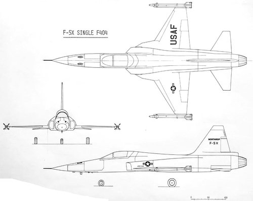
Increasing the F404 engine's thrust to 18,000 pounds was necessary to meet Korean and ADF requirements, which required hauling big AIM-7 missiles and an additional 650 gallons of fuel to meet the range/loiter requirements. This was most inexpensively achieved through development of a new Full Authority Digital Engine Control System (FADEC) for the F404. Although this was a linchpin of General Electric's future plans for the engine, as usual, GE insisted that Northrop pay the cost for development of the FADEC and the 18,000-lb-thrust F404. However Northrop would be reimbursed for its investment with only the promise of future royalties on sales of the engine on other aircraft. Remarkably, this royalty arrangement was not formally agreed until after the F-20's cancellation.
Technical Description

MAIN FEATURES


  • 18,000 Lb Thrust Class
  • 7.8:1 Thrust To Weight Ratio
  • Stall Free Performance
  • Low Bypass Ratio
  • Smoke Free, Low IR Signature
  • Rapid Throttle Response
  • Idle To Intermediate Rated Power In Less Than 4 Seconds -- No Throttle Restrictions
  • Low Specific Fuel Consumption
  • Utilized Jet A-1, JP-4, JP-5, or JP-8 Type Fuels
  • Pneumatic Cartridge Starter or Optional Jet Fuel Starter
  • Simple Starting Procedures
  • Automatic Restart, and Manual Control Backup Systems
  • Automatic Redundant Ignition
  • Bird Strike Capability of 1.1 Pounds

  • Six Individually Replaceable Modules
  • No Scheduled Overhauls or Time Change Requirements
  • The High Reliability of the F-20A Engine Meant that the Average Engine Would Be in the Shop Only One Time In Two Years of Operation (At 20 Flying Hours per Month)
  • No Engine Trim Required
  • Low Shop Visit Rate: 2.0/1000 Flight Hours
  • Engine Condition Monitoring
Engine line replaceable units (LRUs) were replaceable with the engine installed in the aircraft. Major LRUs were mounted by V band clamps and required no safety wire. Removed engines could be returned to service through simple module replacement by the Intermediate Shop. Modules were then repaired, and only failed components needed to be sent to the depot.
The simplicity of the F-20A engine set a precedent for modern fighter aircraft. Ten compressor stages were used to achieve the pressure ratio in the 26 to 1 class, and there were only two turbine stages. This permitted the use of only three frames and sumps and only five main bearings.

To ensure single engine flight reliability, the F404 GE 100 engine incorporated a highly reliable gear fuel pump and a redundant ignition system. A new gearbox provided additional drive pads for an aircraft hydraulic pump and backup electrical generator, giving the F-20A hydraulic and electrical reliability equivalent to that of a twin engine plane. In addition, the F404 GE 100 engine had a fully redundant control system consisting of independent hydromechanical and electrical backup modes to protect against component or sensor failures.

ENGINE FAULT ISOLATION PROCEDURE
Organizational level fault isolation procedures benefited from such features as the digital electronic control unit, fault flags, and engine temperature cycle counter. Suspected internal faults could be quickly inspected by borescope while the engine was installed. A parts life tracking system eliminated costly premature replacement of components.

ENGINE MODULE CHANGE, INTERMEDIATE LEVEL
The modular design of the engine permitted intermediate level repair to be accomplished quickly through removal and replacement of any of the six engine modules. Times are shown below, along with crew requirements.

F-20A Engine Change Crew Size Modules Times Requirements

Fan 2.3 hrs / 3 crew
High pressure compressor 12.6 hrs / 3 crew
Combustor 6.9 hrs / 2 crew
High pressure turbine 6.0 hrs / 3 crew
Low pressure turbine 3.0 hrs / 2 crew
Afterburner 1.0 hrs / 3 crew

The F-20A engine could be removed and replaced by a crew of three in less than 2 1/2 hours. Ease of intermediate level engine maintenance ensured quick turnaround and high availability.
BORESCOPE LOCATIONS
Thirteen borescope ports (of which ten were accessible with the engine installed) enhanced conventional monitoring methods. They permitted all major Mowpath components to be visually inspected to detect foreign object damage, structural damage, or hot section distress while the engine was installed.

Borescope inspection capability permitted on condition maintenance and eliminated the time and expense of unnecessary engine removal or the need for component replacement on a fixed time basis.

 
The F-20A integrated avionics system provided air to air and air to ground target detection and weapons delivery for supersonic intercept, air superiority, combat air patrol, close air support, and interdiction missions----day or night and under adverse weather conditions.


The avionics design simplified pilot operations, reduced pilot workload, and rapidly provided data for successful combat missions. The design incorporated the newest USAF avionics standards. Primary avionics elements were integrated through a redundant MIL STD 1553B multiplex data bus and controlled by a MIL STD 1750A mission computer using MILSTD 1589 Jovial J 73 language. The computer contained 256,000 words of programmable memory and had a throughput of 1 million operations per second. The computer had a specified MTBF of 2400 hours. The F-20A was able to accept new MIL STD avionics and weapons with a minimum of modification and without additional wiring to the avionics.

TIGERSHARK CONTROLS AND DISPLAYS
The Tigershark display system consisted of two digital display indicators (DDIs), a head up display (HUD), a data entry panel, and a display processor. Integrated controls included a data entry panel, software controlled push buttons surrounding each DDI, and hands on stick and throttle (HOSAT) switches.

The two DDIs, located in the uppermost part of the main instrument panel, were easily visible to the pilot. The left DDI usually displayed mission data; the right DDI was normally assigned to the radar.

When a combat mode was selected by the stick or throttle switches, the HUD and DDIs changed immediately to the appropriate displays; the right DDI displayed the radar format while the left DDI displayed stores management data. The figure below illustrates a typical air to ground stores display with bombs selected.

HEAD UP DISPLAY
The HUD provided head up capability in all modes of flight: weapons aiming and delivery information for air and ground targets, and navigational and flight data. The HUD presented data and sufficient references (aim point, allowable steering error, launch boundaries, attitude, and weapon selection and status) to enable navigation and target acquisition and designation. Air to ground weapons could be released manually using the stick switch or automatically by the mission computer. The figure below shows a typical HUD display for an air to air engagement using AIM 9 missiles.

TIGERSHARK RADAR
The Tigershark avionics system included the General Electric AN/APG-67(V) radar. This radar was an X -band, pulse doppler, digital multimode radar using low pulse repetition frequency (PRF) in the look up mode, medium PRF in the look down mode, and high PRF for velocity search. It had an MTBF of 200 hours and included the following functions:


  • AIR TO AIR --Look up, look down, range while search --Velocity search --Single target track --Air combat modes with automatic acquisition --Track while scan*

  • AIR TO SURFACE --Ground map/Doppler beam sharpened map --Display freeze mode --Ranging --Moving target indication* --Moving target track* --Beacon track (option)*

  • AIR TO SEA --Sea surface search (SEA 1) --Sea moving target indication (SEA 2)* --Sea moving target track*
INERTIAL NAVIGATION SET (INS)
The F-20A AN/ASN-144 ring laser gyro INS was the primary navigation, attitude, and heading reference. It provided an all attitude self contained navigation capability anywhere in the world. Precision data were continuously available without degradation during all types of maneuvering and speed ranges. INS accuracy was better than 1.0 nmi/hour CEP.

The ring laser gyro used no moving parts. It operated by measuring the frequency difference between two counter rotating laser beams. The simplicity of the ring laser gyro resulted in a specified MTBF of 2000 hours and significantly improved navigation performance and rapid alignment.

The INS alignment time was 22 seconds, using position data stored prior to aircraft shutdown to facilitate fast scramble time.

BUILT-IN MAINTENANCE DIAGNOSTICS
The Tigershark featured built in (on board) system maintenance diagnostics for detection of failures at the line replaceable unit (LRU) level. Thus, no avionics flight line support equipment was required and scheduled inspections were reduced. Built in test (BIT) capability was included in the LRUs of the avionics system and the electronic flight control system. BIT failure data was processed by the mission computer and displayed on the digital display indicator.

When BIT indications resulted in LRU removal and replacement, the failed LRU was repaired at the intermediate level shop LRU test station using already available test equipment and off the shelf computers. Intermediate level testing identified the fault to the shop replaceable unit (SRU), which was then replaced; the failed card was then forwarded to the depot or supplier for repair.

 
The Inside Story
The Tigershark radar was initially defined, under Carter administration policy, as one that had to be inferior to the APG-66 on the F-16A. By the time the radar subcontractor was selected, Carter was out of power, and the Tigershark was in competition with the F-16A for export orders. So the initial configuration defined was one that was superior to the F-16A in all aspects, except radar range. By 1983 the F-20A was now being considered in competition with the F-16C which had an entirely new-technology APG-68 radar equivalent to the F-20A. So the Extended Range Radar was defined, with additional features and increased range that leapfrogged the APG-68. At each step of this process the F-20's radar was believed to be superior technologically, with lower weight and cost, and higher reliability, than the F-16 equivalent.

F-20 Radar Selection

The F-5E used a modest Emerson radar that was little-more than a gunsight and fire-control aid for the advanced versions of the AIM-9 Sidewinder. Taiwan's fighter requirement was for capability to launch the AIM-7 Sparrow radar-guided missile. This would require a much more capable radar. Candidates considered in various configurations of an advanced, re-engined F-5X aircraft in the period 1977 to 1979 assumed a stand-alone radar supplemented existing F-5E avionics. Likely candidates in these studies were a version of the F-16 radar with a smaller antenna to fit in the F-5 nose, or a new design proposed by Emerson Electric. In May 1979 it was decided to revert to the 'Engine Change Only' F-5G-1 with F-5E avionics for marketing and ITAR clearance purposes. However the specification for a much more ambitious and advanced avionics suite was being refined for eventual development under an 'F-5G Phased Improvement Program'.

In August 1980 definition of the F-5G-2 configuration was completed. Specifications were released in the fall, and competitive bidding held in the first quarter of 1981. The new radar was would be part of an completely new-technology avionics suite, connected together using a MIL-STD-1553 data bus. The radar would take full advantage of the digital revolution, offering 16 radar modes for a variety of air-to-air, air-to-ground, and air-to-sea missions. At the same time bidders were asked to quote options for additional modes, which would take the radar to a capability beyond that of the APG-66 in the F-16A. This was prohibited under Carter's PD-13, but Northrop had an eye on future development potential for the radar, and a possible change in the administration at the White House in the November 1980 presidential elections. Radar bids were received from:


  • Westinghouse made the lowest, most credible offer. This was also the most obvious radar for the F-20 - a version of the AN/APG-66 developed for the F-16. Westinghouse already had in-hand design concepts with less power or smaller antennae for smaller aircraft (F-5 and A-4 upgrades, AV-8B, etc). However the radar was somewhat old technology, being derived from the F-16's unnetworked, semi-analogue design. Furthermore, Westinghouse would be beholden (and possibly accept instructions) from its primary customer General Dynamics. Having the Tigershark's major competitor in control of the radar was an unacceptable complication and hindrance in development and marketing. Furthermore, the radar by definition could never be as good as essentially the same radar offered with a larger antenna in the General Dynamics F-16/79 competitor to the F-5G.
  • Hughes was in control of the high-end radar market, building the AWG-9 for the F-14 and the AN/APG-63 for the F-15 and AN/APG-65 for the F-18. This was a higher bid, reflecting the 'Cadillac' nature of the radars from which it was derived.
  • Emerson Electric, Saint Louis - builder of the F-5E radar. Emerson had been promoting a new, completely different radar for F-5 upgrades for some years. However the F-5E set was very limited, and Emerson did not bring to the table any engineering experience in modern digital radars. But they hoped to stay in the field at the low end of the fighter market with a new radar. They were willing to co-invest, but the radar they were offering was much more limited than the other competitors. Furthermore Northrop's experience with Emerson on the F-5E had not been entirely pleasant. It was doubted that they could provide the sort of cutting-edge super-reliable product Northrop was looking for.
  • Norden/ELTA, Norden being the American front company for an Israeli ELTA radar design. This was also an interesting concept technologically but there would be issues in marketing the aircraft with this radar to Middle Eastern customers (which made up some of the F-20's main prospective market). Northrop could not afford to develop two radars. So this proposal was really a non-starter.
  • General Electric (at Utica, New York). The team there had followed a whole different path of airborne radar development for years, culminating in the immense and sophisticated system for the US Navy's flying radar station, the E-2C. In the process they had mastered a whole series of sophisticated signal processing technologies. Furthermore they had demonstrated new forms of digital processing in a fighter-sized breadboard radar developed for DARPA. GE's CEO, "Neutron" Jack Welch, had set the requirement that every General Electric division had to become number one or number two in its field or be closed down or sold off. The employees at Utica therefore had the most powerful motivation possible to make a new radar succeed. The radar they were offering would use digital processing to operate in more than two dozen modes, with upgrades and additional modes being relatively easy to add later. This was the only way to become at least number two in the radar field and survive.
    But the problem with General Electric was that Welch adamantly refused to 'co-invest' with Northrop in development of the F-20. He was willing to accomplish development on a cost basis without profit, but there was no way he was going to risk GE stockholder's money in development of an aircraft with no guarantee of sales. Northrop would have to pay the cost of radar development if it selected GE. General Electric's price was in the lower range of those received.
So despite the expense, General Electric was selected for the radar. The General Electric radar was selected, and a Master Agreement for design, development, and options for 512 production aircraft was signed on 5 June 1981. The baseline development program had a cost of $64 million; however from the beginning Northrop authorized $7.5 million worth of engineering options which took the radar beyond the capability limits set by the defunct Carter administration's PD-13. Average cost per radar for the 500 shipset master agreement to the beyond-PD-13 configuration was $628,912 in 1986$.

In October 1982, with the Taiwan sale blocked and no immediate launch orders in view, Northrop decided to reduce the effort it was funding to the minimum necessary to fly the GI1001 avionics test and demonstration aircraft while still keeping the program in a position to still deliver aircraft within 24 months of an order. For the equipment subcontractors this meant completing qualification test on their equipment so it would fly on GI1001; but deferring the multiple-lifetime reliability test that was to ensure that the equipment would be of the highest quality in production aircraft.

This gruelling test consisted of taking two production-representative radars, subjecting them to thousands of hours of simultaneous pressurization / depresurrization and thermal cycles equivalent to what they would see in service. At the same time they would be shook, rattled, and rolled at forces far higher than they would ever seen in service. Every time this torture resulted in a failure, the reason would have to be found; the cause corrected in the design; and then the test restarted, until two aircraft-lifetimes without a failure attributable to design were achieved.

Deferring this test meant stopping work on two preproduction systems. But at the same time the engineering team working on the radar would have to be kept together, to complete qualification for GI1001 flight test, and then to support flight test of the aircraft. Since each avionics vendor was responsible for the software in their system, this would also mean software support to modify the programs in each system if problems detected in flight test had to be rectified. This, inevitably, meant that the cost of Northrop and it co-investing subcontractor's programs would now start growing beyond that originally planned.

GI1001 began flight test in August 1983. Discussions with the Koreans produced enough confidence to begin development of the improved equipment the Koreans required to exceed the F-16C in all performance parameters. Development of this advanced F-20 aircraft was started in November 1983. In the case of the radar, the cost of the one-year delay was $ 18.87 million. During this period Northrop had also switched to a dual-redundant MIL-STD-1553 bus to ensure the 'digital aircraft' would remain operating even in the event of major battle damage. This change cost another $200,000 in aircraft development and increased the cost of the 500 shipsets of radars to $840,985.

Upgrading the radar to match the range of the new AN/APG-68 on the F-16C meant a large number of changes. The range was mainly achieved through more sensitive signal detectors and processing, and by increasing the size of the radar antenna. The larger radar antenna was accommodated without changing the aircraft mold line and aerodynamics by mounting it farther aft within the radome. This however meant design changes to the aircraft structure to rearrange the equipment bays in the aircraft nose. This in turn was made possible by the decision to develop a new-technology single gun to replace the obsolete twin-M39 guns inherited from the F-5E. It was also decided to incorporate into the baseline and demonstrate the aircraft's AIM-7 Sparrow radar-guided missile capability.

Construction of a single prototype (system 7) of the new larger-array antenna was authorized. All of the changes (17 in all) to upgrade the radar to the new long-range, AIM-7-capable configuration amounted to an extra $2.6 million. Supporting continued fight test and debugging of the radar was another $3.4 million through the third quarter of 1986. To complete development, qualification, and reliability test of the new radar after a production go-ahead would cost another $33.9 million. The recurring cost of the radar rose again to $ 888,460 for 500 shipsets in 1986$.

A final radar version for the 1986 USAF Air Defence Fighter mission required the addition of new Electronic Counter-Counter-Measure modes to defeat the efforts of incoming Soviet bombers to jam or deceive the F-20 radar. These additional modes would have cost another $43 million in nonrecurring costs and brought the radar unit price over $ 1 million.

To summarize then:


  • January 1981: Original radar as specified in Request for Proposal (Taiwan / Carter PD-13 requirements): $64.03 million development cost, $ 553,540 price per system for 500 shipsets
  • June 1981: Radar as contracted with improvements beyond those in PD-13: $ 71.53 million total development cost, $ 628,912 price per system
  • December 1983: Additional costs due to delay in start of production, and to add a dual redundant MIL-STD-1553 data bus and other lesser engineering improvements: $ 90.6 million development cost, $ 840,985 price per system
  • March 1986: Additional costs to develop Extended-Range Radar version, with AIM-7 capability, plus additional engineering support during continued delays to production start: $ 96.67 million development cost, plus $33.92 million additional cost for a new program to complete development and qualification for production of the ERR version: $ 130.59 million development program, with $ 888,460 price per system.
  • September 1986: Cost to develop a further version of the radar to include ECCM modes for the USAF Air Defence mission: $ 43 million; final total radar program cost $ 173.59 million with the price for 500 shipsets $ 1,013,460 each.
By comparison, costs and performance of radars used in competing aircraft in this period were:


F-5G-1​
APG-67​
GE​
$ 628,912​
270​
F-16A​
APG-66​
Westinghouse​
$ 761,055​
270​
F-20A​
APG-67 ERR​
GE​
$ 888,460​
270​
F-16C​
APG-68​
Westinghouse​
$ 1,406,879​
394​
F-18​
APG-65​
Hughes​
$ 1,230,000​
340​
Taiwan IFA​
*​
Westinghouse​
$ 990,000​
230​

* radar originally proposed by General Electric for the Taiwan Indigenous Fighter. They later selected the GE APG-67 instead.


After the F-20

The APG-67 ended up being used in its intended applications after all - it was selected over Westinghouse equivalents for the Taiwan Indigenous Fighter (later called the Ching Kuo); a Taiwan F-5 upgrade called the F-5-2000; and the Korean A-50 light fighter/trainer. However it never received a major order, and true to his word, Neutron Jack sold the GE radar business to Lockheed Martin in the defence consolidation of the 1990's. In an ironic twist, Northrop-Grumman bought the Westinghouse radar business in the same period, so that today Northrop builds the F-16 radar, and its competitor Lockheed-Martin the radar that would have gone into the F-20.

Technical Description
The F-20A avionics system incorporated the highly reliable General Electric AN/APG-67(V) radar, designed for a 200 hour MTBF. It was an X - band, pulse - doppler, digital, multimode radar, using low pulse repetition frequency (PRF) in the look up mode, medium PRF in the look down mode, and high PRF for velocity search.

The detection range of the AN/APG-67(V) permitted the F-20A to detect most adversary aircraft before the F-20A, with its low radar cross section, was detected by the adversary.

FEATURES


  • Modular design
  • X band coherent pulse doppler
  • Digital, multimode
  • Low, medium. and high PRF
  • FUNCTIONS
    • AIR TO AIR
      • Look up, look down range while search
      • Velocity search
      • Single target track
      • Air combat modes with automatic acquisition
      • Track while scan*

    • AIR TO SURFACE
      • Ground map/doppler beam sharpened map
      • Display freeze mode
      • Ranging
      • Moving target indication*
      • Moving target track*
      • Beacon track (option)*

    • AIR TO SEA
      • Sea surface search (SEA 1)
      • Sea moving target indication (SEA 2)*
      • Sea moving target track*
  • CAPABILITIES

    • Range: 80 nmi (maximum displayed)
    • Angular coverage: 160 degree cone
    • Map resolution: 45 feet at 5.0 nmi
    • Beamwidth: 3.7 degrees azimuth, 5.4 degrees elevation
    • Air to ground range accuracy: 50 feet or 0.5 percent of range
    • Air target detection (fighter size target) --Look up--47 nmi --Look down--38 nmi
    • Sea target detection (patrol boat size target) --Sea 1--47 nmi --Sea 2--40 nmi
  • CHARACTERISTICS

    • Antenna: 16.7 by 26.2 inches
    • Power: 2340 VA
    • Weight: 270 pounds
    • Volume: 3.1 cubic feet
    • Reliability: 200 hours MTBF

 
Dual Digital Flight Control System With 3 Axis Control Augmentation Plus Full Time Mechanical System

The F-20A used advanced aerodynamic technology to achieve high performance with an unrestricted flight envelope. Leading edge extensions (LEX) were carefully designed to control forebody vortices and to provide increased vortex induced lift. The maneuvering flap system provided continuous automatic flap operation to enhance wing efficiency. In the automatic mode, flaps were automatically positioned at the optimal setting as a function of airspeed, angle of attack, pitch rate, normal acceleration, and stick position. Excellent stability characteristics throughout the flight envelope eliminated the need for control system limiters, which otherwise would preclude attainment of maximum angle of attack or limit load factor.

The flight control system combined the advantages of an electronic, or fly by wire, system with the safety and reliability of a mechanical system. Primary flight controls included an all movable horizontal stabilizer, ailerons, and rudder. The flight controls in all three axes were controlled through a combination of pilot-commanded mechanical inputs and the dual digital three axis Control Augmentation System (CAS) commanded by the Flight Control Electronics Set (FCES). In the pitch axis, for example, the CAS system accounted for approximately 40 percent and the pilot's mechanical input for approximately 60 percent of the total control authority of the horizontal stabilizer.

Should the highly reliable FCES have failed for any reason, the mechanical system had sufficient authority under all loading conditions to control and land the aircraft safely.

The F-20A flight control system produced the following benefits:

  • Low pilot workload
  • Low maneuvering control stick forces
  • Neutral speed stability during gear up acceleration
  • Reduced control stick movement
  • Uniform aircraft response
  • Improved tracking capability
  • Operational enhancement
  • Allowed neutral stability center of gravity position
  • Eliminated ballast requirements.
AUTOPILOT
The F-20A autopilot provided the following HOLD modes:

  • Attitude
  • Heading
  • Altitude
  • Mach/airspeed
A control stick steering mode automatically disengaged the selected HOLD mode when the stick was moved and reengaged when the selected conditions were met and the stick was released.
HANDLING QUALITIES

Excellent handling qualities were provided throughout the flight envelope by a combination of aerodynamic characteristics and a flight control system optimized to allow precise control with reduced pilot workload. Above 350 KCAS, a constant maneuvering stick force gradient of approximately 4 pounds per g was provided. Below 350 KCAS, where the aircraft could maneuver to maximum lift conditions at high angles of attack, the gradient increased with decreasing airspeed to yield a constant stick force as a function of pitch rate. The F-20A's high degree of departure and spin resistance and its highly responsive flight system allowed the pilot to maneuver aggressively without fear of departing the aircraft.

Performance and operational reliability of the flight control electronics system (FCES) were achieved by a dual digital flight control computer (FCC). The FCES combined high reliability with a simple actuation scheme that capitalized on performance gains of relaxed static stability while achieving excellent handling qualities. In the event of multiple failures of the FCES, control reverted to the active mechanical control system, with handling qualities sufficient to allow the pilot to return to base and land safely.

Increased mission operational reliability was provided in the FCES through dual channels of air data computation by the digital air data unit (DADU). The DADU supplied Mach number, altitude, and dynamic pressure data to the FCC and the mission computer.

Required air data parameters were computed and transmitted by the DADU to the radar, HUD, and environmental control system through the FCC interface with the MUX bus.

OVERSTRESS REMINDER

The F-20A flight control system incorporated a computer controlled "g reminder" system designed to prevent inadvertent overstress of the aircraft. As the aircraft reached limit load factor, the normally low and constant stick force per g increased substantially, informing the pilot that he was at design limit load factor. Limit load factor was automatically computed by the pitch CAS computer as a function of external stores loading and fuel state. In an emergency situation, however, the pilot could override the system by pulling through the increased resistance.

 
RELIABILITY SUMMARY
The F 20A Tigershark demonstrated unprecedented reliability throughout the flight test program.

Mission reliability during the flight test program was consistently greater than 95 percent. Field measured data indicated that the F-20A reliability was 159 percent better than anticipated. These data confirmed Northrop's approach to reliability and showed that the expected level at maturity of 6.00 field inherent MFHBF (mean flight hours between failure) was conservative.

MFHBF
Avionics 18.07 MFHBF
Engine 190.00 MFHBF
Airframe 9.43 MFHBF
-------------
Total aircraft 6.00 MFHBF

MAINTAINABILITY SUMMARY
Design assessments, demonstrations, and measured data indicated that the specified 5.6 direct maintenance man hours per flying hour (DMMH/FH) maintainability requirements for scheduled and unscheduled organizational and intermediate levels of maintenance would be met before 100,000 cumulative fleet flight hours. Three quarters of the F-20A maintainability figures were based on measured empirical data.

Field measurements were conducted on flight test aircraft at Edwards Air Force Base, California. Intermediate and depot level support were provided by Northrop suppliers; therefore, these data were not measured. However, all organizational level maintenance data were collected.

MAINTENANCE INDEX (Maintenance Man Hours per Flight Hour)

Airframe & systems 2.64
F404 GE 100 engine 0.45
Avionics 0.52
----------
Total unscheduled maintenance - intermediate level 3.60
Inspection 2.00
----------
Total (DMMH/FH) 5.60
General support 5.50
----------
Total (MMH/FH)--organizational and intermediate levels 11.10
 
The gun armament for the F-5A, F-5E, and the F-20 consisted of two M-39A cannon. These had been developed in the 1950's and produced initially in vast numbers for the F-100 Super Saber, the first supersonic fighter-bomber (1,395 built). The cannons were government-furnished-equipment - that is, they were provided from US government inventory. M-39 production had ended in the 1950's, and by the 1980's there were just over 300 shipsets remaining. This meant that either production would have to be restarted, or a different gun would have to be fitted.
The gun issue for the F-20 was a problem from the beginning. The 'engine change only' model used the F-5E forward fuselage and radar, so there was no issue. The original F-5G version of the F-20 offered to Taiwan in 1978 required a different radar in order to be capable of firing the AIM-7 Sparrow radar-guided missile. This was solved in the initial offering by deleting one of the M-39 cannon and using the extra space for the additional black boxes required for either a new Emerson radar or a modification of the F-16 AN/APG-66 radar with a smaller antenna. For the F-20, the new AN/APG-67 General Electric radar was fitted, with much larger and numerous black boxes, and a much larger antenna than the F-5E's Emerson radar. This required a new, larger radome. To accommodate all of this and still fit two M-39 cannon and the larger Panoramic Canopy, the F-20 was fitted with a completely redesigned fuselage forward of station 341.37 (aft of the canopy frame). The use of a 'shark nosed' radome actually improved the aerodynamics of the F-20, and suggested the designation Tigershark.

With South Korea looking like the launch customer by 1983, it was apparent a major radar modification would have to be made to meet the Korean's demand that the F-20 match the F-16's radar range against MiG-23 targets. This would require a larger radar antenna and more power. Elongating the fuselage or making any major change to the mold line was out of the question for aerodynamic reasons. So it was decided to move the radar installation aft so that the larger antenna would fit farther back in the existing radome. The equipment bays would have to be rearranged in the nose, and this meant either deleting one of the M-39 cannon or developing a new gun.

Aircraft guns were thought to be obsolete in the late 1950's. Major fighters of the period were developed without any gun at all (MiG-21, F-4). The Vietnam War, when fighters on both sides had to resort to just chasing the opposition around the sky without a weapon after all missiles had been fired and missed, proving the fallacy of that engineering judgment. The post-Vietnam fighter series (F-14 through F-18) were all equipped with guns. Logically these high-tech fighters would have been equipped with new-technology cannon. But all of these fighters were equipped with derivatives of a General Electric M61 Gatling gun, developed in the 1950's for the Century fighter series. Developing a new gun, it turned out, was really difficult. To design and test a complex, fast acting, pneumatic-hydraulic-mechanical device that would operate in horrendous vibration, low temperature, near-vacuum environments was a process that required countless thousands of hours of development and firing tests. Furthermore aircraft guns, although deemed necessary after all missiles had been expended, were considered low-tech, un-glamorous, and low-priority. The US Air Force had tried and failed to develop such a gun for the F-15 in the 1970's, and ended up equipping it and the F-16 with the M61. The Navy followed suit on the F-14 and F-18.

Bill McDowell, the F-20 project manager, was a card-carrying gun nut. He had been pushing for development of a new aircraft gun for years. By the 1980's a vast improvement on the M61 would be possible. A gun using caseless 30 mm ammunition would pack much more punch, be much more accurate, fit into a smaller space, and be less prone to jamming and mechanical problems than the M61. But he had the same problem convincing Northrop management of the merits of pursuing such a development that gun advocates in the services had in convincing the Pentagon. The Korean requirements finally provided the opportunity.

Ford Aerospace had acquired the old General Electric aircraft gun business in the 1970's. They were considered the sole source for a new gun for the F-20 (as is usual, management supports competitive bidding for subsystems, until it comes to a type of equipment in which they feel they have personal expertise. Then they just want to buy from the company that they 'know' is best). Ford, being by then integrated into the humungous automobile company, was immensely lethargic, bureaucratic, intransigent, and difficult to deal with - the antithesis of the usual F-20 co-investing vendor. Northrop was going to have to pay for the whole development, but get little in return in terms of royalties or data rights. Nevertheless, McDowell finally got his gun, and management probably took a 'we'll worry about that later' since the Ford subcontract would only result in significant liabilities if the South Korean or USAF ADF orders were awarded and the F-20 finally proceeded into production.

 
The AIM-7 Sparrow guided itself through passive radar homing. That meant that the launch aircraft had to illuminate the missile's target with a source of continuous wave radio energy. The missile's homing head could use the reflections of that energy from the target to track and home in on the target. The F-20 would require a continuous wave illuminator (CWI) to accomplish that task. The only company to have developed such a device for use in a small aircraft was Ericsson in Sweden, for the Viggen aircraft. In order to meet the customer's requirement for AIM-7 capability, a sole source contract was awarded to Ericsson for development of a CWI for the F-20. This was, paradoxically, the only foreign subcontractor for the F-20 and at the same time the only one involving handling of classified material (the AIM-7 homing frequencies and other software/hardware interface documentation were classified Secret). As part of the contract, Ericsson would modify an existing CWI to fit in one of the F-20's gun bays. This would be used to demonstration-fire an AIM-7 from an F-20. After a year of very hard work by both Ericsson, the General Electric radar team, and the Northrop engineers, the AIM-7 was successfully fired from GI1001 on 27 February 1985. It successfully downed a Northrop BQM-104 drone 13 miles away.
The balance of the contract involved development of a production CWI specifically for the F-20. This miniaturized version would fit into a tight space in a belly bay of the F-20's nose, under the radar installation. Like all of the other traveling wave tubes and other delicate electronics in the nose, this CWI would be subject to an atrocious vibration environment when the F-20 fired its guns. When the F-20 was terminated, Ericsson's $ 1 million termination claim was accepted without on-the-spot fact-finding or a trip to Sweden to conduct negotiations. Northrop Internal Audit was suspicious of this settlement, but it had been mandated by management and they were called off when they questioned the matter.

 
Yet another shortfall of the F-20 in comparison to the F-16 was the instantaneous and sustained turn rates. The F-20 was the best gun platform flying, with the most stable point-and-shoot capability in the air. Yet, like all of the other differences between the F-16 and F-20 that the Koreans flung in Northrop's face, this was one that management decided had to be addressed. The thin 1950's-vintage supersonic wings of the F-20 allowed no conventional technical solution. Therefore the engineers decided they would, for the first time in a combat aircraft, use electromagnetic actuators together with new maneuvering flaps which would increase the effective wing area in maneuvering situations by 10%. These infinitely-variable flaps would allow the F-20 to out-maneuver the F-16 in all situations and were the wedge that could lead to later F-20 models being 'all electric' aircraft, with no hydraulic actuators, accumulator, pumps, or lines. However it was yet another (virtually!) leading-edge technology. For a while it looked like the disc-shaped actuators could not be thin enough to fit into existing wing mold line. There was even the possibility that aesthetically-disastrous-but-aerodynamically-inconsequential bumps would have to protrude from the wing surface to accommodate the actuators. Fortunately it was found the actuators could actually be built within the specified depth, and the bumps would be unnecessary. Development of the actuators was another element of the production-model F-20 that was barely begun at cancellation, but could have resulted in significant development and production delays, risks, and extra costs.

 
Increased fuel would be necessary to meet the Korean's insistence that the F-20 match the F-16's range performance in their standard mission. Every nook and cranny of the small, tightly packed airframe was examined for places fuel could be stashed. The thin wings, which already accommodated the landing gear, provided no space for fuel tanks. A 'wet' vertical stabilizer - cramming fuel into the fin - was considered, but the small amount that could be fitted there was not worth the extra weight, complexity, and center of gravity problems. Finally the only solution was to replace the F-5E bladder tanks of the fuselage with integral fuel tanks, and to carry larger external tanks. This allowed internal fuel to be increased from 4400 gallons to 5050 gallons. Performance of the aircraft, despite the extra fuel, would be maintained by a further increase in the thrust of the F404 engine from 17,000 lbs to 18,000 lbs. The change also meant the interior bays of the fuselage would have to be sealed fuel tight. This was achievable, but at what cost in production complexity and maintainability problems? Nevertheless the change went ahead, putting the F-20 yet higher on the cost/performance curve that could lead to asymptotic increases in production and support costs.

 
Other changes for production F-20's can be traced back to a comment made by an Air Force logistics general at a logistics meeting. Northrop was touting, as usual, the high reliability and low maintenance of the F-20 compared to other aircraft. The general finally burst out in frustration "You just don't get it. I have to man squadrons according to mil standards. The only way for your low maintenance to translate to savings for me is to eliminate airman specialties". This meant going through the official USAF specialty codes and looking for what unique specialties were hardly required and could be eliminated through changes in the aircraft. Therefore the liquid oxygen supply used for the environmental control system was eliminated, and with it the oxygen cart and its associated technician and logistics tail . So another high-tech, but higher-maintenance, more complex, and more expensive device replaced the liquid oxygen tank and regulator - an OBOGS, or On-Board Oxygen Generating System. This was a molecular sieve, that sucked in the thin air of high altitudes, screened out the harmful ozone, and concentrated the oxygen for use by the pilot.
Official Description:The F-20A used a state-of-the-art onboard oxygen generating system (OBOGS) that eliminated the need for a liquid oxygen (LOX) system by concentrating oxygen from compressor bleed air. The OBOGS system eliminated the need for LOX support equipment and its associated logistics problems, thus reducing F-20A turnaround time.

The performance and simplified support requirements of OBOGS were verified by evaluation on the AV-8B Harrier. Man-rating testing of the OBOGS system were completed by Brooks Air Force Base. The prime component of the OBOGS system was the oxygen concentrator. The concentrator, which was driven by aircraft ac power, worked on the molecular sieve absorption (surface adhesion) principle, separating a small percentage of oxygen, along with inert gases, primarily argon, from the airflow on each cycle. The concentrator contained two canisters of zeolite, one canister of which was purged while the other was in the oxygen-generating cycle. The cycle time for operation on each canister was about 5 seconds with in-let air alternately directed to each canister by a motor- driven valve. This valve was equipped with a sensor connected to a caution light in the cockpit, which alerted the pilot of any mechanical or electrical power-supply failure.

Concentrated oxygen-enriched air entered a storage plenum in the concentrator. The plenum contained as large a volume as practical, maintained at approximately 80 psi. The storage plenum automatically provided the pilot with up to 16 minutes of oxygen during short-term high demands or low-output periods, i.e., air system/electrical system failures or engine flameouts. The plenum also prevented multiple short-term use of the emergency gaseous oxygen (GOX) system and thereby eliminated subsequent added servicing requirements to replenish the GOX supply.

A low pressure switch, installed in the supply line immediately upstream from the oxygen regulator, was connected to the caution light which alerted the pilot if oxygen pressure dropped to 15 psig. OBOGS had a negligible effect on the F-20A environmental control system (ECS). It used less than 2 pounds of air per minute, which translated to less than 3 percent of available air from the ECS refrigeration package.
 
Other changes for production F-20's can be traced back to a comment made by an Air Force logistics general at a logistics meeting. Northrop was touting, as usual, the high reliability and low maintenance of the F-20 compared to other aircraft. The general finally burst out in frustration "You just don't get it. I have to man squadrons according to mil standards. The only way for your low maintenance to translate to savings for me is to eliminate airman specialties". This meant going through the official USAF specialty codes and looking for what unique specialties were hardly required and could be eliminated through changes in the aircraft. So the original F-20 had a hydrazine starter for air restarts and ground emergency scrambles from remote locations. This made the starter compact, lightweight, and capable of being loaded with hydrazine and then waiting, inert, for months or years before being called into use. But hydrazine was nasty stuff, toxic. It required special fueling trucks, and most importantly, a USAF specialty code. So for the production F-20 Northrop decided to go with a jet fuel starter - much heavier and maintenance-intensive, but using the same fuel that powered the aircraft itself.

 
Honeywell, the provider of the laser inertial navigation system (INS), was a typical case of a co-investing F-20 subcontractor. They had a certain management / engineering team who had come to Honeywell from the INS market leader, Litton. They were preaching the gospel of the laser gyroscope, something they were unable to get Litton to promote vigorously enough.
Conventional INS systems used rotating mechanical gyroscopes that went back to the platforms developed by the Germans for the V-2 in world war II. This cage of four nested rings would be spun up, and then its resistance to rotational movement measured and translated into changes in the angle of the aircraft compared to that when it was powered up. Accelerometers mounted in three axes in the INS measured accelerations in each axis. Summing up these acceleration measurements, combined with the information as to the orientation of the aircraft, allowed the computer in the INS to calculate the aircraft's position and orientation at all times, relative to its original position. Naturally these mechanical devices were not completely accurate, and small errors accumulated over time. The typical conventional INS by the late 1970's drifted an average of 1 nautical mile per hour of flight.

These mechanical gyroscopes were precision devices, with high-precision bearings and special lubricants. They took a few minutes to warm up and then spin up after power-on. The pilot would have to wait for this period of time before the aircraft could start rolling. This meant that aircraft on runway alert, awaiting a scramble order, had to have their engines running, their electrical power on, and their INS already aligned and operating, in order to make an instant start.

The laser gyroscopic had no moving parts and used the phenomenon of wave interference familiar to high school physics students. In the Honeywell laser gyro, a triangular cavity was machined into a block of super-high-quality glass, which was resistant to deformation in heat or cold. Each corner of the triangle had a mirror, and the cavity was filled with a lasing gas. Once turned on, two exciters began laser beams cascading in opposite directions within the cavity. These counter-rotating beams were combined in a prism and reflected to a photocell pick-up. The two beams of the same frequency produced different interference patterns depending on whether the glass block was rotating or not. The diffraction bands would march at a certain rate up the photocell if it was rotating in one direction, downward for rotation in the other direction, with no motion if there was no rotation in that axis. Therefore the output from the photocell could be used to determine the direction and magnitude of rotation. A set of three gyros, one in each axis, provided a gyroscope package that would replace the conventional mechanical gyroscope.

The laser gyro's accuracy depending mainly on its physical size. Honeywell was developing a whole family of these gyros for different application. Those for navigation by ship or nuclear submarine were enormous, over a foot in diameter, and the errors would be less, for something that might spend days before getting a positional update near the surface. Tiny laser gyros were made for precision artillery shells, which had a time of flight measured in seconds. For a fighter aircraft, with a flight time of an hour or tow, gyros about nine inches in diameter were used.

Honeywell's laser gyros used a triangular cavity, while those built by Litton were rectangular. But the boys that had left Litton for Honeywell oversold the ease with which the new technology could be implemented. Finding the right glass, the right fabrication methods, the right hardware and software engineering solutions to using the signals from the gyros, proved daunting. Honeywell had already sold laser gyro systems to the airlines, which had a benign flight environment and could receive constant positional updates from radio navigation aids. But for the F-20, the INS would have to retain high accuracy throughout the flight without radio updates, in order to allow precision bomb delivery and navigation to targets in hostile territory. And it would have to retain this accuracy during violent maneuvers, the vibrations of gun firing, and while exposed to the thin air and low temperatures, or thick air and high temperatures, in an external equipment bay.

The development was sold to Honeywell management as being easily accomplished, taking about 12 months, and costing $1.5 million. In fact the problems multiplied, and it took 18 months and cost nearly $7 million. Meanwhile LItton had filed a lawsuit against Honeywell and the two former Litton employees for theft of trade secrets. The sales manager who had oversold the whole thing to Honeywell was eventually fired; the suit was settled out of court; but Honeywell persevered and ended up with a world-beating product, dominating the laser gyro market for years before LItton finally entered it.

The inertial navigation system had an extra circuit board that performed the role of backup bus controller. In the event of failure of the mission computer, this Honeywell-programmed board provided a minimum set of mux bus traffic control commands and functions to allow the aircraft to get home.

The laser gyros, cast and machined out of milky blocks of super high quality glass, were calibrated in the sub-basement of the Honeywell facility in Minneapolis. Here, in a controlled environment, the gyros were mounted on cement blocks which were in turn cast into the glacier-scrubbed granite bedrock of the North American continent. This room of gyros, glowing red as they slowly sensed the rotation of the earth, was a truly eerie sight.


An example of an undetected software bug in the F-20 INS occurred during the two-aircraft world tour. After GG1001 crashed in Korea, GI1001 had to make the lonely trip home, alone, across the north Pacific from Hawaii to Alaska. The two aircraft had traveled around the world easterly, flying from California, to Farnborough in England, then across Europe, North Africa, and Asia. As the aircraft crossed the international date line for the first time, the inertial navigation system went haywire. The pilot had to use the compass, and once within range of Alaska, radio homing to navigate. After landing, shutdown, and restart in Alaska, the system worked fine. The problem was found to be a multiplier with the wrong sign deep in the software code. The problem would never emerge until the moment the aircraft first crossed the international dateline, going from west to east.

Honeywell observed that Northrop required the F-20 navigation system to pass a much more severe environmental qualification test than Honeywell's Space Shuttle Main Engine controllers.

 
The Head-Up Display selection went to General Electric's Binghamton, New York facility, as part as a package with the radar and engine. This was certainly one of the really odd choices. GE had no particular expertise in modern head up displays, its previous experience being the bizarre head-down reflective gunsight of the F-4E and the heads-up reflective gunsight for the F-5E. For the F-20 they were going to provide a conventional reflective HUD using a green raster display - the type of technology used in the popular video games of the time, Tank or Asteroids. This had a few technical advantages - excellent visibility in bright light, and incapable of being taken out by low power laser counterstrike weapons. But it looked decidedly old-fashioned compared to the panoramic, holographic head-up displays being developed by Marconi and Hughes for other aircraft. Replacing the GE HUD with a more modern Marconi unit became a priority soon after the comments on the F-20 started coming in from customer pilots who compared it unfavorably with other fighter displays. However, given Marconi's allegiance to General Dynamics and the F-16, discussions with Marconi had to take place in great secrecy. Taking a leaf from the black programs, a Northrop team consisting of a test pilot, an engineer, and a buyer flew to Phoenix under assumed names and using all cash transactions. They were taken through the back door of the Marconi facility and demonstrated the latest and greatest in HUD technology. The pilot flew an F-16 simulator to get an idea of the HUD in action (he was mightily impressed with the simulator, noting that when he flew through a barn he could see the countryside through the slats). Satisfied with the verification, a quiet procurement action resulted in GEC Marconi being selected to provide the HUD for the production F-20.

 
Another also-ran, Bendix Teterboro, was selected for the head-down displays (called Digital Display Indicators on the F-20). Bendix had been a leading supplier of conventional round-dial instruments for aircraft going back to World War I. They had provided the cabin pressure altimeter for the F-5E (adapted from a B-58 instrument). Their records were so comprehensive that at the time of the YF-17 selection they were involved in trying to identify whether certain instruments found in the Pacific might have come from Amelia Earhart's lost Lockheed Vega. But the writing was on the wall. The last generation of fighters (F-16, F-18) had abandoned the 'non-critical' round-dial instruments in favor of electronic displays. The next generation (F-20, F-16C) would eliminate the analogue gauges entirely with only a couple of 'round dials' as back-ups in case of total electrical system failure. Bendix had to break into the aircraft electronic display market or leave the aircraft instrument business entirely.
The electronic displays could be programmed so as to display different information in different ways according to the phase of flight. They could serve as radar displays, moving map displays, or replace conventional instruments such as artificial horizons or engine gauges with electronic equivalents. The screens were surrounded by strips of buttons, which would have a different function depending on the display mode, the purpose of the button being displayed on the screen next to it. They even had a mouse function, using a conical 'Chinese hat'on the pilot's stick, which cold move a cursor around the screen to designate a target, update a navigational waypoint, or select a menu item. These first aircraft screens were monochrome green raster displays, the only type at the time that was bright enough to be visible in daylight. Some US vendors had the first prototype color liquid crystal displays barely working in their labs (a technology in which they lagged years behind Japan and would soon give up entirely).

 
Northrop assigned development of the software for each avionics system to the individual suppliers. But they still needed an overall program to operate the aircraft. To operate this they needed what Northrop called a mission computer, which would sort through the mux bus traffic from the other systems, analyze the data, and send out orders. For example, for a bomb drop, the mission computer would take position and velocity data from the inertial navigation system and the air data computer; radar data; and calculate the appropriate moment for bomb release for the target designated, send the necessary data to the head-up or head-down displays for the pilot to monitor; and then send the necessary series of bombs away signals to the Pylon Interface Units, which would translate them to the appropriate electrical and software commands to the top of ordnance carried.

 
Paul,

I want to personally thank you for your posts today. They brought back a lot of memories, as I was involved with the program for a brief period.

One thing some of those of us at our level advocated (but weren't agreed with ) was as our "sponsor" (other countries wanted a US military sponsor for credibility and to facilitate FMS) the US Navy instead of the Air Force. We wanted this for three reasons:

First, the F-20 used a variant of the F404, the engine for the F/A-18, a plane for which Northrop had a major workshare. A lot of the F404 parts could be supported out of the Naval Supply System, which enhanced credibility in potential customers' eyes, while the F404 had no commonality with anything in the Air Force.

Second, the F-20 was not in competition with any Navy program, a BIG point, whereas since the Air Force was also the sponsor for the F-16 so there would be a bit of a conflict of interest there. Each F-20 sold meant an F-16 wasn't sold which could mean that each F-16 USAF bought might cost a bit more. Potential customers for F-20 generally weren't potential customers for F/A-18. In fact, the F404 for USN might even be a little bit cheaper if more were being bought for F-20.

Besides those reasons, the Navy loved to mess with the Air Force.
 
Fascinating thread about the F5/20. Apologies for what is a rather frivolous aside. Back in 1964 the makers of the TV series "Stingray" liked the F5 so much they bought an updated version for the "World Aquanaut Security Patrol".
 

Attachments

  • 8ea776bf878a39b2b2b916ef2dcf1918.jpg
    8ea776bf878a39b2b2b916ef2dcf1918.jpg
    74.3 KB · Views: 407
For the proponents of the tigershark, what was its range going to be with 2 slammers and winders? Was it even close to the 16? Seems like what I read way back 35 years ago it was more tailored to small nations without the need for protecting large swaths of airspace. Also I am curious if the cockpit was larger than the 5 which I've heard some pilot complaints about.
 
Range would have been lesser. The F404 has higher fuel burn than the F100, so even with the same fuel fraction, the F-20 would be at a disadvantage.
 
For the proponents of the tigershark, what was its range going to be with 2 slammers and winders? Was it even close to the 16? Seems like what I read way back 35 years ago it was more tailored to small nations without the need for protecting large swaths of airspace. Also I am curious if the cockpit was larger than the 5 which I've heard some pilot complaints about.
Post 45 from this thread has info and range diagrams for different missions from a Tigershark brochure.
In case the Federation of American Scientists page disappears or goes to a fee-based model.

Source:

It also has about half the bomb load of an F-16. But the mission is different. The Air Force turned the F-16 into an A-7 (and F-4) replacement rather than the LWF it was originally designed to be. It remains a potent fighter, but it was evolved into a bomb-truck.

The F-20 mission is more like that of a Viggen or Gripen AB/CD* in Swedish service. Easy to maintain, quick reactions to defend airspace, a couple of Mavericks for anti-armor, basically high-tempo operations with a lot of sorties in defense of territory rather than offensive or penetration missions. Ideal for Taiwan, South Korea, Switzerland, and the like. Intercept a strike mission, back to base. Sink a couple landing craft. Back to base. Hit an armor column. Back to base. Rince and repeat. But it's also a useful companion to high end aircraft, since it can handle the less demanding missions, freeing F-14s/F-15s/Mirage 4000s (Mirage 4000 and F-20? That's an 80s could-a-been dream casting.) for penetrating counter air and deep strikes.

*The EF seem to be an F-16-like evolution in terms of interdiction/strike/penetration capability.
 
After GG1001 crashed in Korea, GI1001 had to make the lonely trip home, alone, across the north Pacific from Hawaii to Alaska. The two aircraft had traveled around the world easterly, flying from California, to Farnborough in England, then across Europe, North Africa, and Asia. As the aircraft crossed the international date line for the first time, the inertial navigation system went haywire. The pilot had to use the compass, and once within range of Alaska, radio homing to navigate. After landing, shutdown, and restart in Alaska, the system worked fine. The problem was found to be a multiplier with the wrong sign deep in the software code. The problem would never emerge until the moment the aircraft first crossed the international dateline, going from west to east.

Didn't something similar happen in more recent times? i'm going to say it was a flight of 4 F-22s going to Hawaii during its early days, but i could be wrong.
 
F-5S 3-view on metal. Note only one 20mm gun. On sale at eBay for $180. In an early post in this thread Hesham mentions the F-5S was for Sweden but I have never seen it before. 1st image is from eBay, 2nd image is my attempt to clean it up a little.


Attachments

  • F-5S.jpg
    F-5S.jpg
    284.9 KB · Views: 351
  • F-5S a_edited-1.jpg
    F-5S a_edited-1.jpg
    412.8 KB · Views: 388
F-5S 3-view on metal. Note only one 20mm gun. On sale at eBay for $180. In an early post in this thread Hesham mentions the F-5S was for Sweden but I have never seen it before. 1st image is from eBay, 2nd image is my attempt to clean it up a little.

It tics a lot of the same boxes as the Gripen does, but did the Tigershark have the STOL capability to utilize Sweden's "road" basing?
 
F-5G Modification Joins Swedish JAS Competition

Paris—“Big-wing” version of the Northrop F-SG, redesignated the F-5S, has been proposed as a low-cost contender for the Swedish air force’s JAS fighter/attack aircraft in a tightly scheduled competition. The Swedish Military Command’s recommendation is due Oct. 1.

A new version of the F-5 is one of five aircraft competing for the fighter selection.
They are:
* Saab-Scania 2105, which is being proposed by Industry Group JAS, a consortium of five Swedish aerospace firms.
* General Dynamics F-16, modified in accordance with the Multinational Staged Improvement Program (MSIP) now under way in the U. S. and the four NATO nations that have selected the aircraft. In effect, the aircraft being offered to Sweden by General Dynamics is the same as will be delivered to USAF in 1985.
* McDonnell Douglas F-18, essentially unchanged from the one that will be produced in the mid-19805 for the U. S. Navy, but with the addition of a landbased, mobile landing arrester system that uses twin drag chutes to stop the aircraft once it has touched down.
* Northrop F-18L, with weaponry modified to meet Swedish requirements.

The F-5S version of the Northrop F-5G will have a wing 25-30% larger than the wing on the F-SG and will have modified flaps. The changes are designed to improve the F-5S’s landing characteristics to enable it to land in 1,500 ft. and meet Swedish requirements for operations from dispersed small airfields and road sections.The new wing design also would likely improve some flight performance, but officials said the primary goal was to shorten the landing distance. The F-5S also would have its armaments capability modified to meet Swedish
needs, including provision for the larger gun and the RBS.15 missile.
- Aviation Week, 15 June 1981
 
Seems that with all the upgrades ( and rebuilds ) F-5E have had over the last 30 odd years, their systems are equal, if not superior, to what the F-5G/F-20 would have had. The only thing lacking is the much improved performance bestowed by the single, larger engine.
The J-85-GE21 turbojet has a max diameter of 22 in, and a weight of about 700lbs. Two engines provide for 7000lbs thrust dry and 10000 with reheat.
The IHI XF-5 lo-bypass turbofan, used in the Japanese stealth demonstrator, with advanced (ceramic composite ) materials allowing for turbine entry temperature of 1600 deg C, and press ratio of 26:1, has a diameter of 24 in. weight of about 1200 lbs, and roughly the same length.
However, two engines produce 20-22000 lbs of thrust with reheat.

Main problems associated with such an upgrade, would be revising intake ducts for almost double the airflow,
rearward shift in CoG making the aircraft more neutral, if not unstable in pitch, possibly needing a fly by wire system, and the cost of the new engines ( probably many times the cost of the semi-disposable J-85 ).
 
Great idea. Sounds gorgeous. You'll certainly find today a gamut of small companies willing to do it for cheap.

But don't bother too much acquisition cost, the gain in reliability regarding J85 swap might solely offset the extra cost (plus available electrical power for systems like a high powered aesa radar and directional jammer) .
 
Last edited:
Interesting that originally Northrop planned using an F-5F for the conversion. A 2-seater F-20 would make a nice WIF.
 

Attachments

  • 2 view.jpg
    2 view.jpg
    111.6 KB · Views: 365
  • Differences dwg.jpg
    Differences dwg.jpg
    61.2 KB · Views: 355
  • F5E 404 Changes.jpg
    F5E 404 Changes.jpg
    117.5 KB · Views: 348
  • Demo.jpg
    Demo.jpg
    264.7 KB · Views: 357
  • F5X 3-view.jpg
    F5X 3-view.jpg
    117.2 KB · Views: 401
It's interesting to know they originally considered an F-5F, since the actual F-20 two seat version wasn't longer than the single seat F-20. It just placed the second cockpit behind the first and displaced the fuel tank there, like most modern fighter designs. My understanding is there were some serious control limitations with the F-5F, due to it's longer nose shifting the center of mass forward, but the stabilators remaining the same size as those of the single seat F-5E.
 
How do you guys think the F-20 compares to the F-CK1 Ching Kuo?
originally it seems the F-20 was intended for Taiwan, and once the Taiwanese learned they couldn't get it, they built their own plane, but with two engines.

the only thing I know besides them being roughly the same size/weight class
is that the F-CK-1 seems to have some problems with its engine, as its derived from a civilian engine
 
It's interesting to know they originally considered an F-5F, since the actual F-20 two seat version wasn't longer than the single seat F-20. It just placed the second cockpit behind the first and displaced the fuel tank there, like most modern fighter designs. My understanding is there were some serious control limitations with the F-5F, due to it's longer nose shifting the center of mass forward, but the stabilators remaining the same size as those of the single seat F-5E.
They actually added approx. 200 lb of lead to the tail to pull the cg into range.

That makes sense, but they would still have the added area in front of the CG they still couldn't compensate for without larger tail surfaces.
 
is that the F-CK-1 seems to have some problems with its engine, as its derived from a civilian engine

The F-CK-1's engines are Honeywell/ITEC F125-70 Turbofans which are after burning versions of the Honeywell/ITEC F124 engine which is itself derived from the civilian Honeywell TFE731 of which there are more than 11,000 produced and used in multiple platforms. The F124 itself is also used in the Aero L-159 Alca and Alenia Aermacchi M-346 Master.
 

Similar threads

Please donate to support the forum.

Back
Top Bottom