I know a little the story you're talking about. Sometime in the 90s a SecDef and the SecUSAF had proposed the usaf field a stealthy swing low altitude penetrator to take over the role of the retired F-111and to replace the strike eagle. It went no where. They allegedly wanted to buy something like 400 of these monsters. What we got instead was more funding for the JSF and the super hornet. Its probably in a book i read and others here can probably correct me if I recall this wrong.

If its true then its awfully revealing that the problems of swing wings and stealth are solvable and the US stealth know how has moved beyond simple shaping. At least that’s what I read into it.

Sounds a bit like the mythical A-17 that as far as I know was only mentioned in Popular Science.

 
Last edited:
I know a little the story you're talking about. Sometime in the 90s a SecDef and the SecUSAF had proposed the usaf field a stealthy swing low altitude penetrator to take over the role of the retired F-111and to replace the strike eagle. It went no where. They allegedly wanted to buy something like 400 of these monsters. What we got instead was more funding for the JSF and the super hornet. Its probably in a book i read and others here can probably correct me if I recall this wrong.

If its true then its awfully revealing that the problems of swing wings and stealth are solvable and the US stealth know how has moved beyond simple shaping. At least that’s what I read into it.

Sounds a bit like the mythical A-17 that as far as I know was only mentioned in Popular Mechanics.

https://assets.documentcloud.org/documents/4357755/11-L-0559-First-Release-Bates-1-912.pdf

In April 2001, former Secretary of the Air Force Don Rice sent Rumsfeld a letter arguing for the restart of the B-2 program, complete with diagrams supposedly showcasing the cost savings of payload delivery by B-2 compared to an equivalent payload weight delivered by cruise missiles. In that letter, Rice suggests that “a long-range, dwell capability for electronic combat-manned or unmanned-would be valuable in many circumstances,” foreshadowing the long-endurance drones of the 2010s, and possibly even anticipating the optionally manned nature of the still-in-development B-21 bomber. Rice also suggested that the Air Force abandon the Joint Strike Fighter program and a proposed “stealthy F-111” program, ,,,

VG and or BWB would assist in dwell
The F/A-18 was not what the USN wanted and now the carrier aviation wing is about half century out of date in a peer.to.peer fight.
 
Last edited:
The swing wing is more complex and hence will require more maintenance. That is easily determined using engineering failure mode analysis techniques. With the advent of Computational Fluid Dynamics software and other Finite Element design tools you can develop wings which encompass lift enhancement devices for take-offs and landings while retaining good cruise performance all without swinging the wing. The swing wing was an evolutionary step that has seen its day. Why go backwards to swing wings when you can get as good or better performance from other designs? None of the 6th gen fighter designs to date show a swing wing nor does the B-21 or a whole bunch of UCAV's.
 
Unless someone displays that AFRL has terminated morphing wing technology dev (a type VG) one would have to beg to differ.
 
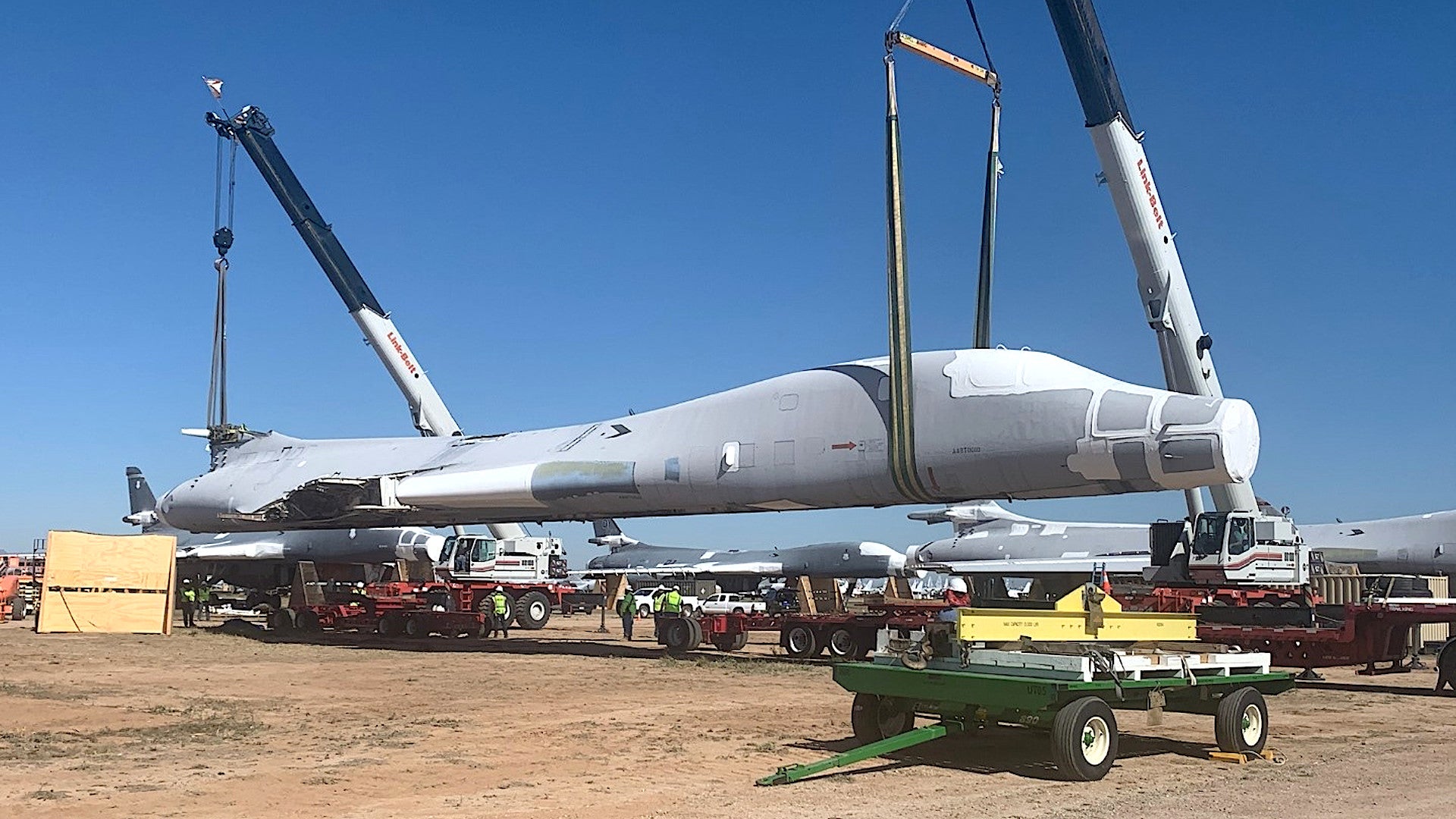
Anyone know what B-1B it was that got sent to the Boneyard?

The article talks at some length about the B-1B airframe that was taken from storage.

If you're asking about what airframes were placed in storage before, here is AMARC's inventory page for the B-1B:

 
Anyone know what B-1B it was that got sent to the Boneyard?

The article talks at some length about the B-1B airframe that was taken from storage.

If you're asking about what airframes were placed in storage before, here is AMARC's inventory page for the B-1B:


Thanks for the extra info TomS.
 
,
It's hard to believe that scanning a physical object is the best way to build a digital model that will be used to understand the condition of the fleet. Each individual part differs from other examples within whatever tolerances were in effect when the part was produced. I'd think that it would be far better to work from the drawings, which include tolerencing representative of all examples and don't require disassembly.


Do they have the drawings? What condition are they in? What file format did they use? Is the CAD package still in existence? Do you know how long it takes to go from a drawing to a 3D printable model?
 
I would say that 3d scanning on the aircraft, won't help you much to predict fatigues and local strains without an extensive work that would require a full set of drawings. Then, the problem that you have starting with the drawing is that modelizing such complex assembly would cost you too much (time, workforce etc..) and will be met with quality escape and implemented design evolutions that might not be fully documented (those are complex projects).

A 3D scan will only allow you to match fit a part that had to be resourced or modified and check the validity of the new design in the assembly with local simulation. The name of the game is "Local".

Then eventually you can have a multi-pronged approach to rapidly rebuilt larger assemblies.
But the extend of the work will largely depend of the ressources you poor-in.

Here, the USAF IMOHO is more simply looking to document a serial representative airframe that contractors will be able to work with in their design, cutting cost of future modification or sustainement endeavors (part resourcing etc...).
 
,
It's hard to believe that scanning a physical object is the best way to build a digital model that will be used to understand the condition of the fleet. Each individual part differs from other examples within whatever tolerances were in effect when the part was produced. I'd think that it would be far better to work from the drawings, which include tolerencing representative of all examples and don't require disassembly.


Do they have the drawings? What condition are they in? What file format did they use? Is the CAD package still in existence? Do you know how long it takes to go from a drawing to a 3D printable model?

Scan output is a plot file that most software convert in a single surface file. You can easily 3D print that file directly if the model is suitable for the print process.

3d modeling from manufacturing drawings can be extensive with design evolution not always documented (various contractors manufacturing a single part through time for example).
Time needed greatly vary from a multi-parts per day to a week or more for a single part.

Often you'd need to re-invent the part trying to figure what exactly the process was and what are the compatible tolerances or quirks; that whithin a very short time. If you are serious, there can be a lot of documenting and FEA to match the part on hand.
It works well only if the project leader has a real knowledge of what this work involves. Sadly, too often, this work can be outsourced to contractors selected on the best offer per lots, leaving very few margins to do a proper work.
Agile billing is often needed but not quite well understood by the actors in presence.
 
Last edited:
,
It's hard to believe that scanning a physical object is the best way to build a digital model that will be used to understand the condition of the fleet. Each individual part differs from other examples within whatever tolerances were in effect when the part was produced. I'd think that it would be far better to work from the drawings, which include tolerencing representative of all examples and don't require disassembly.


Do they have the drawings? What condition are they in? What file format did they use? Is the CAD package still in existence? Do you know how long it takes to go from a drawing to a 3D printable model?

Scan output is a plot file that most software convert in a single surface file. You can easily 3D print that file directly if the model is suitable for the print process.

3d modeling from manufacturing drawings can be extensive with design evolution not always documented (various contractors manufacturing a single part through time for example).
Time needed greatly vary from a multi-parts per day to a week or more for a single part.

Often you'd need to re-invent the part trying to figure what exactly the process was and what are the compatible tolerances; that whithin a very short time. If you are serious, there can be a lot of documenting and FEA to match the part on hand.
It works well only if the project leaders has a real knowledge of what this work involves. Sadly, too often, this work can be outsourced to contractors selected on the best offer per lots, leaving very few margins to do a proper work.
Agile billing is often needed but not quite well understood by the actors in presence.


Yep. And this is why they're scanning the parts in. I wouldn't be surprised if there were software out there that could take a scan and auto-populate dimensions for tweaking. The kind of things scanning won't pick up are material properties. Was it machined from billet or a forging? What was the grain direction and material composition? Did it have heat treating or surface finishing? For geometry though scanning is light years away from trying to get the info from a drawing that may or may not exist.
 
But the scan output is a single file: there is no segegrated nuts, bolts, rivets, panels, ribs etc... All is blended into a single 3d model and you need to reconstruct what will be needed for you to use (interfaces, part that have an impact in your simulation, thickness of elements etc...).
Scanning is not a shortcut to design. It's a first step.

From the article, "Once the B-1B arrives at NIAR, researchers will 3D scan each part, "down to the nuts and bolts," to create a highly detailed virtual model that they can reassemble and disassemble at will on a computer."

They're going to tear it apart. Just waving a hand scanner over an assembled airplane would be useless. And nobody said it was a, "short cut to design". The design already exists. It IS however a much more efficient way than wading through a warehouse full of drawings and trying to update that mess to current CAD technology.
That part slipped through my mind in my attempt to put everything on the text. You are right... And, if that was not obvious in my reply, they do know absolutely what they are doing.
They might even use a library of modeled objects to cross reference the scan data and detect if a shape match the projection of a known part.
 
Last edited:
But the scan output is a single file: there is no segegrated nuts, bolts, rivets, panels, ribs etc... All is blended into a single 3d model and you need to reconstruct what will be needed for you to use (interfaces, part that have an impact in your simulation, thickness of elements etc...).
Scanning is not a shortcut to design. It's a first step.

From the article, "Once the B-1B arrives at NIAR, researchers will 3D scan each part, "down to the nuts and bolts," to create a highly detailed virtual model that they can reassemble and disassemble at will on a computer."

They're going to tear it apart. Just waving a hand scanner over an assembled airplane would be useless. And nobody said it was a, "short cut to design". The design already exists. It IS however a much more efficient way than wading through a warehouse full of drawings and trying to update that mess to current CAD technology.
That part slipped through my mind in my attempt to put everything on the text. You are right... And, if that was not obvious in my reply, they do know absolutely what they are doing.
They might even use a library of modeled objects to cross reference the scan data and detect if a shape match the projection of a known part.

Hopefully somebody has a BOM and assembly tree structure somewhere. :eek:
 
Video shows an air-breathing missile, so this is not a Skybolt descendant.
 

Attachments

  • Rhfv8q4sUCzAfjmo.mp4_snapshot_00.00_[2020.09.03_17.58.33].jpg
    Rhfv8q4sUCzAfjmo.mp4_snapshot_00.00_[2020.09.03_17.58.33].jpg
    150.8 KB · Views: 175
  • Rhfv8q4sUCzAfjmo.mp4_snapshot_00.07_[2020.09.03_17.58.54].jpg
    Rhfv8q4sUCzAfjmo.mp4_snapshot_00.07_[2020.09.03_17.58.54].jpg
    302.5 KB · Views: 163
Looks like one weapon on each external hardpoint on the B-1B (total 6).

Off hand, those weapons hung on the B-1B look like ARRW. The air-breather later in the segment is a different weapon; the video doesn't show it coming off the B-1B, and it has a different color nosecone.
 

Attachments

  • AIr-Breather.jpg
    AIr-Breather.jpg
    4.7 KB · Views: 174
the video doesn't show it coming off the B-1B, and it has a different color nosecone.
Video shows it coming from the weapons bay at 0:13 actually.

You're right; I missed the aircraft at the top of the frame in my first slow pass through. So, confirmed two different weapons, one of them likely ARRW, the other apparently air-breathing (HAWC, presumably). I think that lines up with the comments in that article from a couple of months ago about using the B-1 to launch hypersonic weapons.

 
Video shows an air-breathing missile, so this is not a Skybolt descendant.
I stand corrected as video actually clearly shows both ARRW and HAWC.


Just for scale, those external pylons were designed to carry 2 AGM-129s on EACH That's 2 x 3700lb+ and the weight of the dual pylon. Anybody know what the hardpoints are rated for?
FAS states a 58,800 lbs max payload externally.
Fwd-Int-Aft stations are rated in a ratio of 2-3-2,
so Forward and Aft station rating is 8,400 lbs and Intermediate station rating is 12,600 lbs
 
Last edited:
Video shows an air-breathing missile, so this is not a Skybolt descendant.
I stand corrected as video actually clearly shows both ARRW and HAWC.


Just for scale, those external pylons were designed to carry 2 AGM-129s on EACH That's 2 x 3700lb+ and the weight of the dual pylon. Anybody know what the hardpoints are rated for?
FAS states a 58,800 lbs max payload externally.
Fwd-Int-Aft stations are rated in a ratio of 2-3-2,
so Forward and Aft station rating is 8,400 lbs and Intermediate station rating is 12,600 lbs

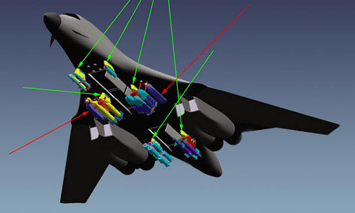
Dennis Jenkins' B-1 Lancer says the design had structural provisions for six dual and two single pylons, but only the six dual pylons were actually wired and plumbed (they could apparently handle external fuel tanks, though none have been ever seen loaded). He describes these six stations as the "forward-most," suggesting the two non-wired stations are further aft, presumably along the tail section behind the aft bomb bay.
 
two non-wired stations are further aft, presumably along the tail section behind the aft bomb bay.
These two non wired stations are right abreast outboard the Intermediate main stations, not aft of all other main stations.
(Technically they are still aft of forward stations, obvio)

images (27).jpeg
(Not official. For creative use)
Non-wired stations are shown in red arrows.

Loadout for Agm 86B on B-1b prior to Salt2 -
Fwd - 2x(2)
Int - 2x(2) main station + 2x(1) abreast station
Aft - 2x(2)
Salt2 brought it down to 12 and these 2 stations were not used.
 
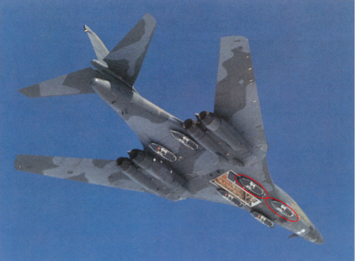
Those pics are B-1R; are all the hardpoints necessarily in the same spots as the B-1B?

I only ask because Jenkins is very good otherwise, and it seems odd he'd be wrong on those two pylon locations. Unfortunately, the book has no drawing of all the pylon locations.

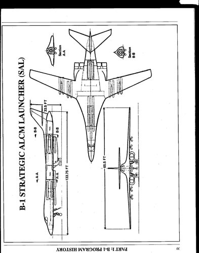
And now for something completely different --proposed Strategic ALCM Launcher configuration of the B-1A from 1979. Very different layout, with six single ALCMs under the fuselage and four twins under the wings. Plus 16 on two internal rotary launchers (total 30 ALCMs), with fuel tanks rearranged to make it all fit, I think. Obviously, this was not an as-built configuration, though.
 

Attachments

  • B1 SAL.jpg
    B1 SAL.jpg
    279.6 KB · Views: 187
Looking at that video it’s interesting how they’ve picked up tricks from Hollywood with the overly dramatic music as if from the latest Michael Bay movie.
 
It's the paradox of war in the 21st century: more and more wars oppose rows of kids that have grown with the same culture.
 
We could see something similar on the other shore of Atlaintic ocean (Pacific as well) - Russia restore production of Tu-160 Blackjacs after decades of launching the last (Soviet-time) example. I'm sure that's not an easy task, though...

Difference is the line never went anywhere. It just collected dust. Big difference.
I think that makes way more sense than destroying production lines. Keep the line, even if nothing is being produced (although ideally you should have some minimal production to keep the supply and spares lines intact), until a replacement is in production. That way if there is an emergency you can build something rather than having no options. Witness the C-17 and F-22 debacles, with lines destroyed and then - hey, we could use some more of those.

Those pics are B-1R; are all the hardpoints necessarily in the same spots as the B-1B?

This box art from years ago suggests the same location:
View attachment 640619

The video looks like they've got one big missile on each of these positions:

View attachment 640620
Those are the six two station pylons. The two single pylons aren't attached.
 
Last edited:

Similar threads

Please donate to support the forum.

Back
Top Bottom