McDonnell Douglas A-12A Avenger II

The Wave

ACCESS: Restricted
Joined
25 November 2015
Messages
32
Reaction score
48
Website
www.artstation.com
Hello,

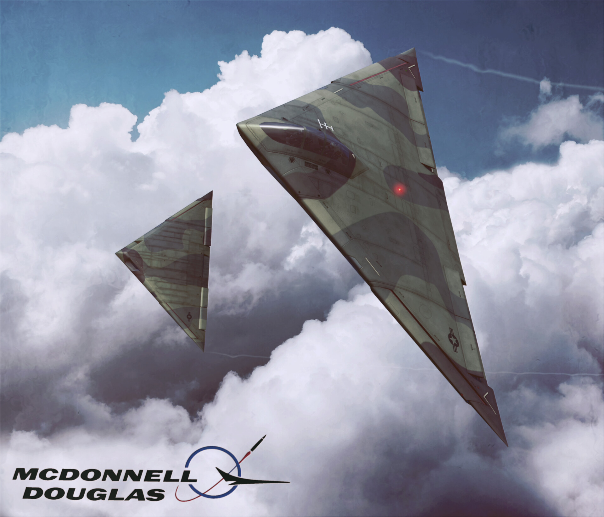
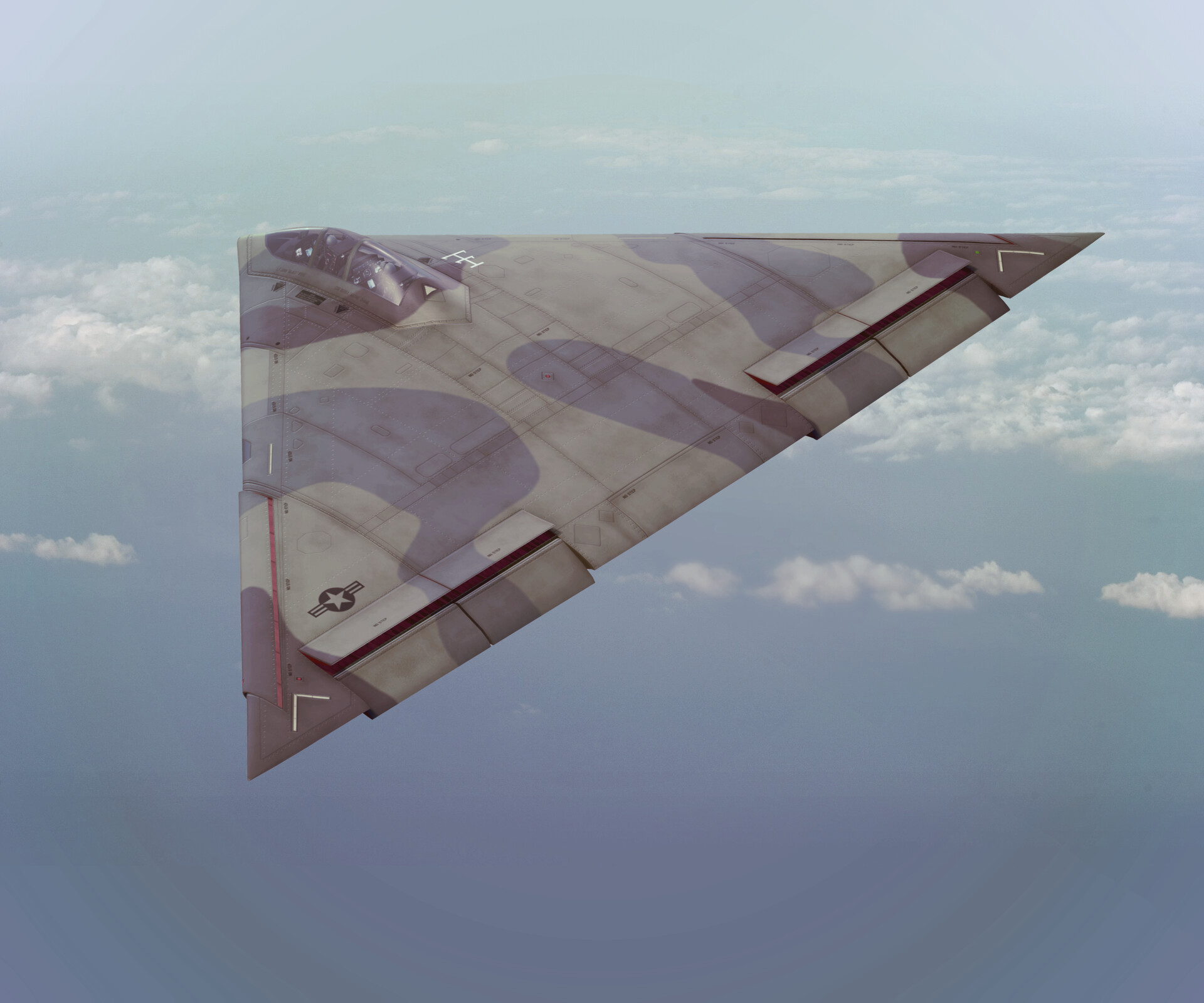
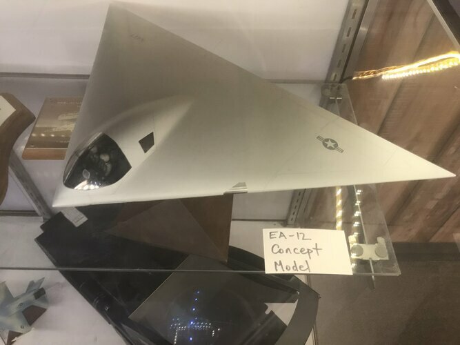
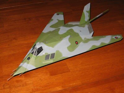
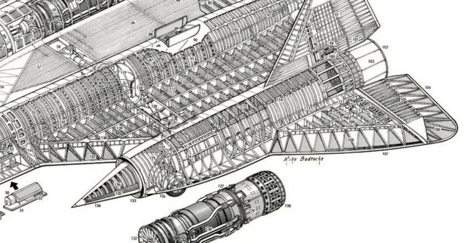
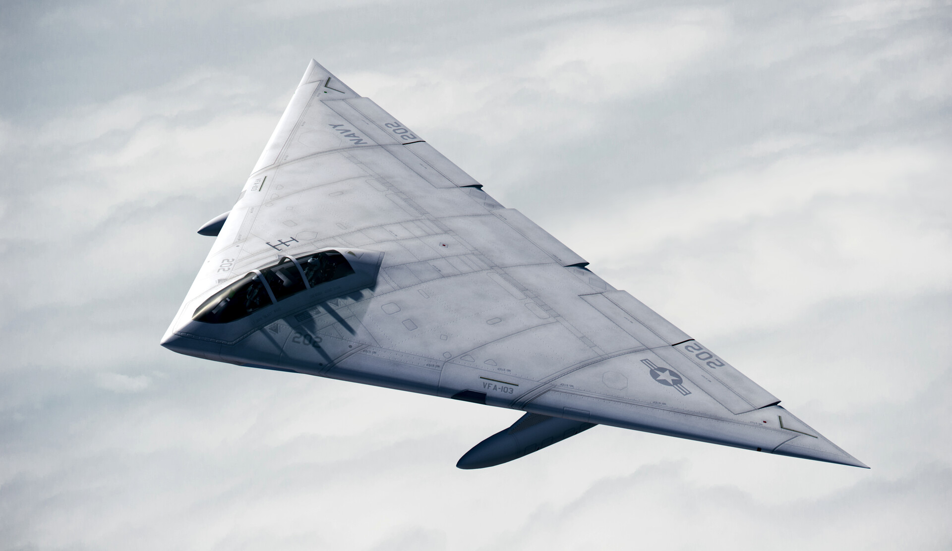
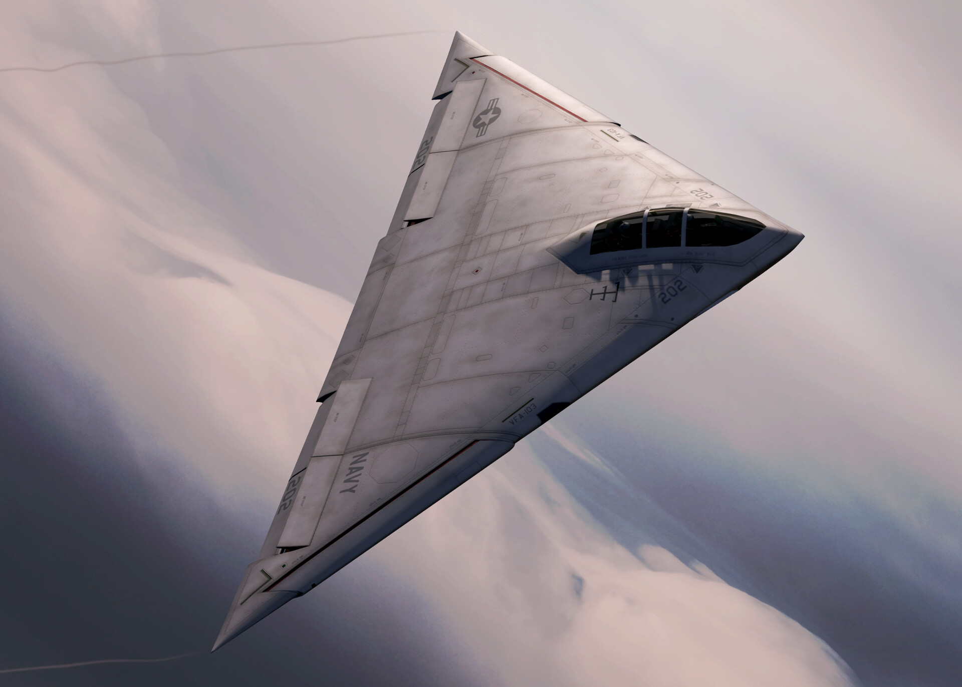
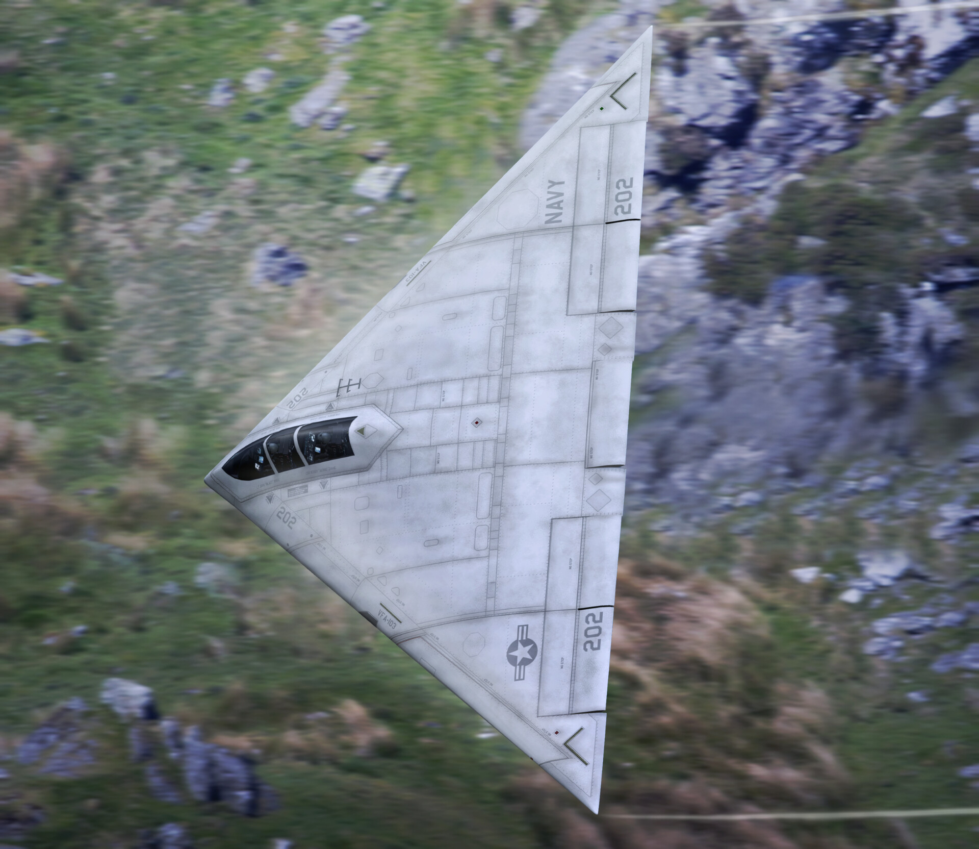
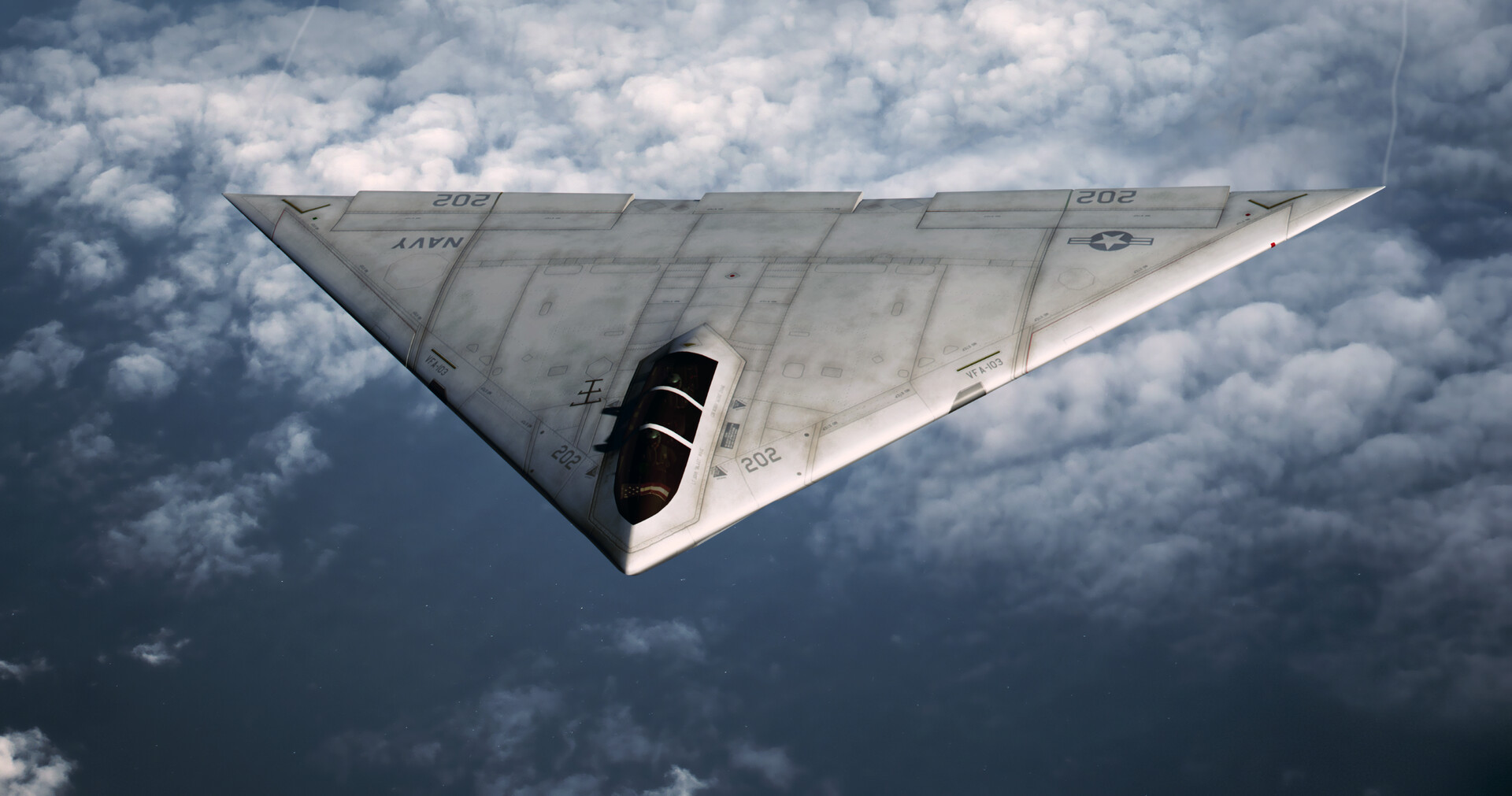
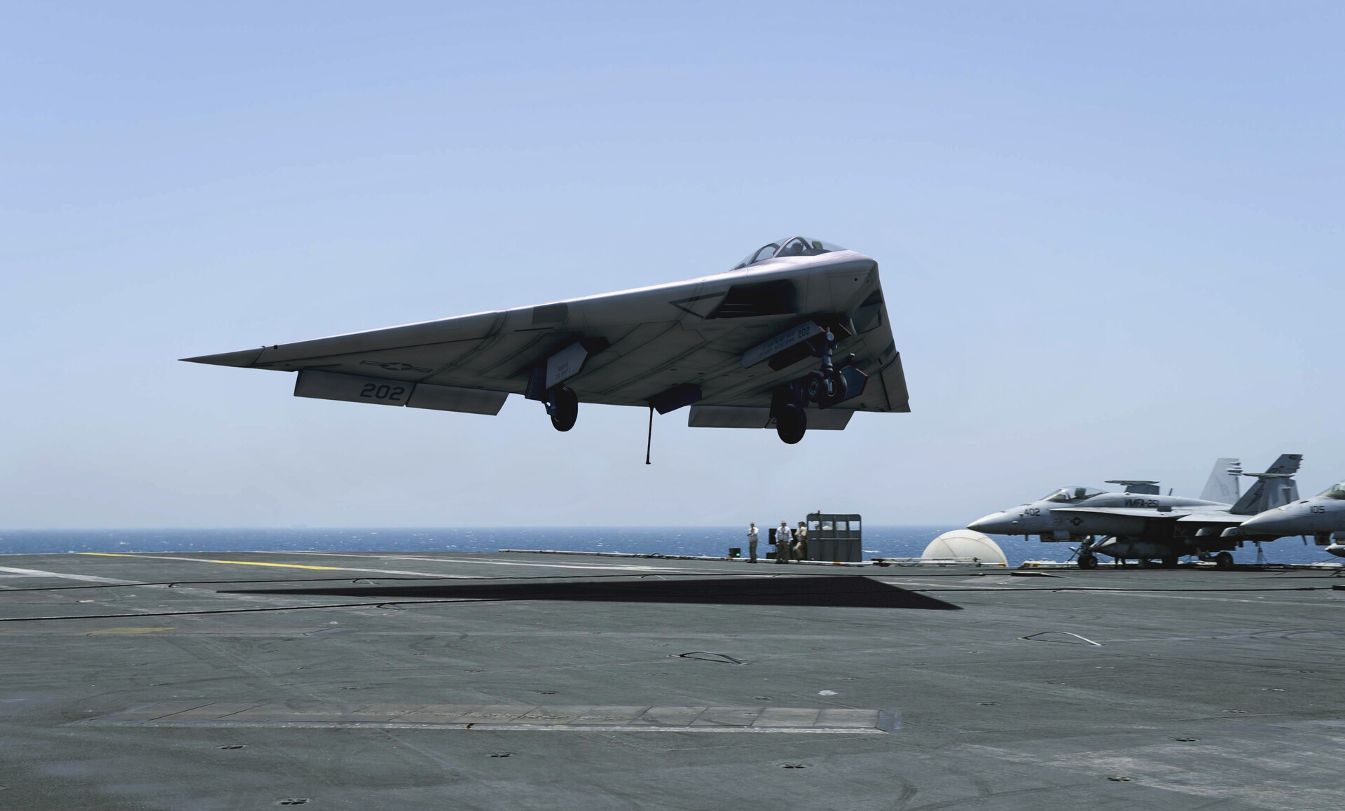
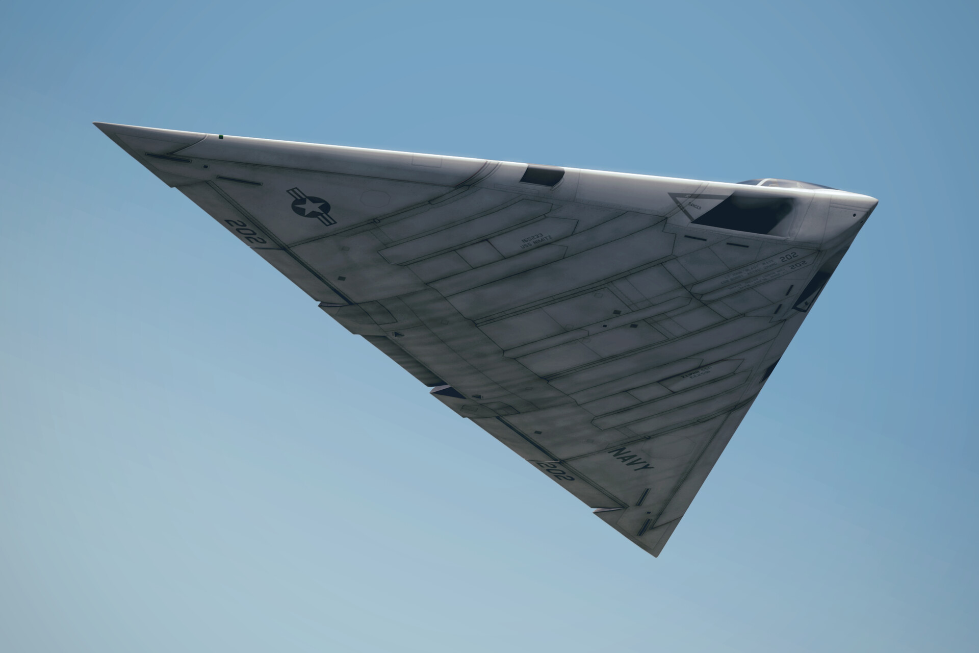
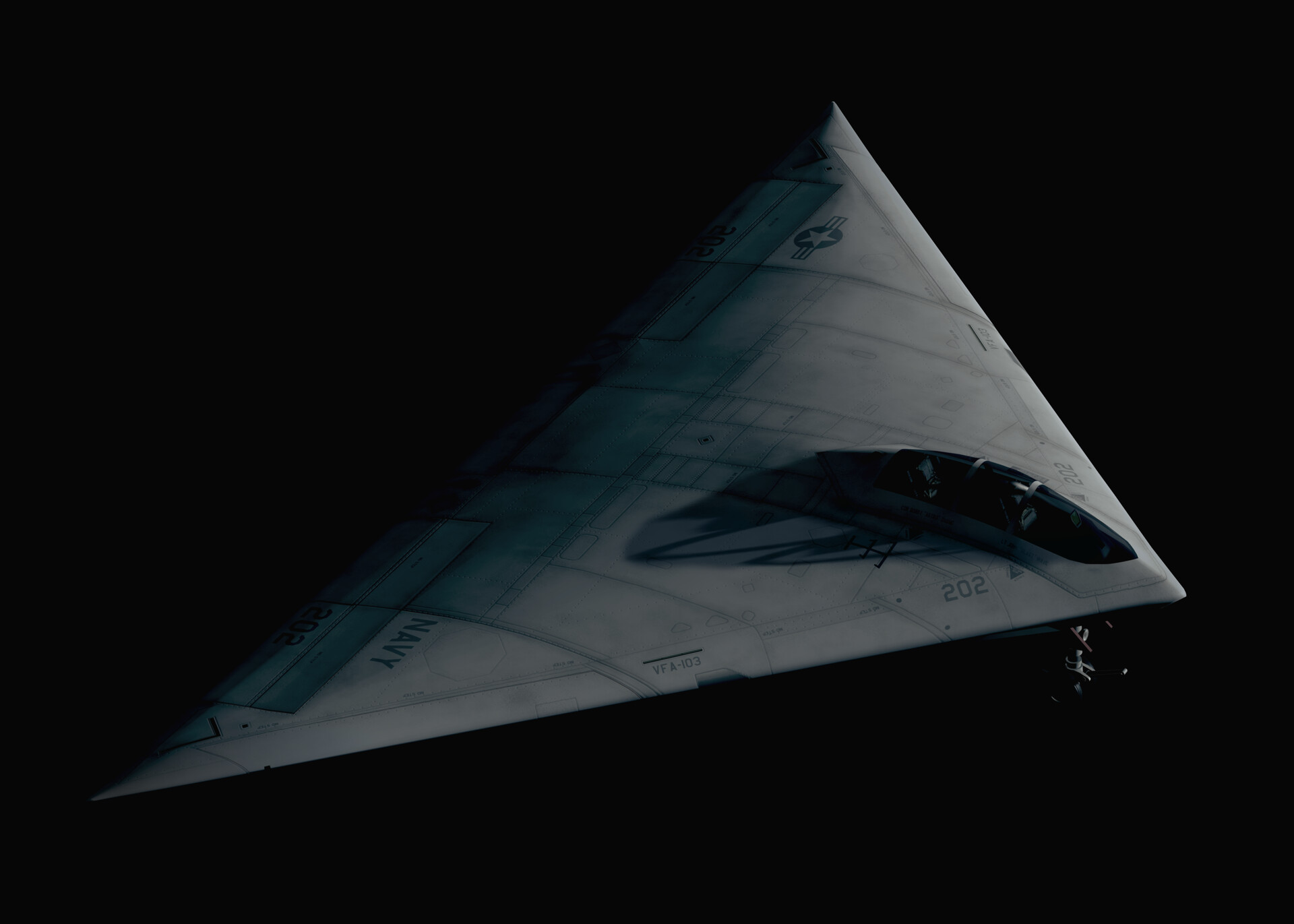
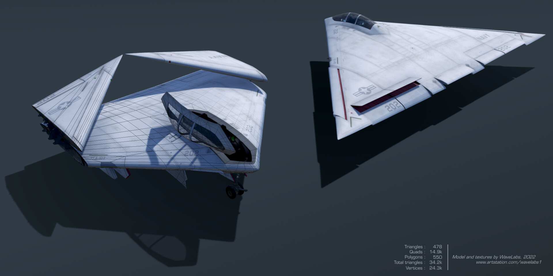
Here are some renderings of a model I was commissioned to create of McDonnell Douglas's never built A-12A Avenger II. While certain details may be of questionable accuracy such as the position of the forward formation lights on the underside, I spent a lot of time studying what few references I could find and basing as much as possible on the full-size mockup as well as the various desktop models.

wavelabs-mcdonnell-douglas-a-12-avenger-ii-render-5.jpg


wavelabs-mcdonnell-douglas-a-12-avenger-ii-render-13.jpg


wavelabs-mcdonnell-douglas-a-12-avenger-ii-render-8-half-size.jpg


wavelabs-mcdonnell-douglas-a-12-avenger-ii-render-6-smaller.jpg


wavelabs-mcdonnell-douglas-a-12-avenger-ii-render-10.jpg


wavelabs-mcdonnell-douglas-a-12-avenger-ii-render-9.jpg


wavelabs-mcdonnell-douglas-a-12-avenger-ii-render-3.jpg


wavelabs-mcdonnell-douglas-a-12-avenger-ii-render-4.jpg


wavelabs-mcdonnell-douglas-a-12-avenger-ii-render-11.jpg


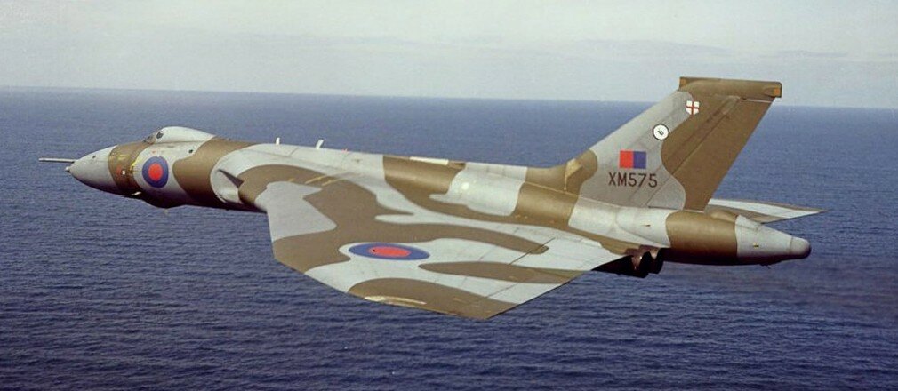
All models and renderings of the A-12 depict it in a light gray US Navy livery, but as this is a 3D model I decided it would be fun to see what such a plane would have looked like in European One camouflage seeing as the F-117 and Have Blue had camouflage liveries.

wavelabs-mcdonnell-douglas-a-12-avenger-ii-render-2-weathered.jpg


wavelabs-mcdonnell-douglas-a-12-avenger-ii-render-1.jpg
 
Posted on the main Avenger thread is this two seater.
The RAF were hoping to get Avengers to replace Tornado in the 90s. I suppose they thought it would replace the two F111 wings in the UK too, so that would be a common NATO theatre asset.
Doubt it would have got camo but I did buy an RAF F117 in a weak moment.
 

Attachments

  • 206863-d688efe023d2812d28834c835eb34b4d.jpg
    206863-d688efe023d2812d28834c835eb34b4d.jpg
    38.9 KB · Views: 188
  • 48-armour-raf-117-stealth-fighter_1_d0863678473ac12bdb9d335957838f44.jpg
    48-armour-raf-117-stealth-fighter_1_d0863678473ac12bdb9d335957838f44.jpg
    24.9 KB · Views: 169
Wave,

Your A-12 illustrations are very nice, but your control surface deflections are "off". The best example of an operational aircraft that used the same elevon control system is the Avro Vulcan in the video below. Note that the trailing edges of the Vulcan's elevons on landing are up putting a download on the tail and raising the nose. This is the opposite of your A-12 landing illustration. In level flight, there shouldn't be much elevon deflection as seen in the Vulcan picture.

View: https://youtu.be/DvFvBbsQVI4?t=82
 

Attachments

  • Vulcan in level flight.jpg
    Vulcan in level flight.jpg
    88.6 KB · Views: 135
Posted on the main Avenger thread is this two seater.
isn't that a 4 (four) seater? See how the note says "EA" for electronic attack that at the time was the Prowler (4 seater).

@Richard N : if the airframe has a relaxed CG or rear CG, it can be that landing will be done with the elevons down or neutral (see for example the M2K that was specifically designed to not need any positive elevon deflection during landing to correct a short coming of earlier Mirage (sink rate)).


Mirage 2000
iu


Mrage IIIS
iu
 
Last edited:
oops sorry..I just went by the two figures in the cockpit.
 
Last edited by a moderator:
"@Richard N : if the airframe has a relaxed CG or rear CG, it can be that landing will be done with the elevons down or neutral (see for example the M2K that was specifically designed to not need any positive elevon deflection during landing to correct a short coming of earlier Mirage (sink rate))."

The two examples you provided don't address anything about being able to use down elevon to land. In the first picture, he had to use up elevon to get the nose up to achieve that angle of attack to land. Once he achieved his landing angle of attack, he centered elevons to to to maintain his landing angle of attack. In the second picture, the wingtip is showing up elevon. There is nothing in these pictures showing deltas landing with down elevon.

The Vulcan landing with its elevons going up to raise the nose shows how those surfaces work. The 30+ degrees of down elevon shown in the A-12 landing picture would dive it right into the deck. The two camouflaged A-12s breaking away from each other would both have up elevons instead of down. Also, look at pictures of airplanes in level flight and notice how their control surfaces are not noticeably deflected.

The Concorde is another example of a tailless aircraft using up elevons on landing as seen in the video.

To learn how elevons work on a delta wing aircraft, some physical modeling might be helpful. Fold yourself a typical delta wing paper airplane. Trim it with clay or a paper clip on the nose until it glides flat without climbing or diving. Fold the trailing edges up and throw the glider and observe what it does. Then fold the trailing edges down and observe. Then use those observations to decide which elevon command you as the pilot would execute as you came over the runway threshold.

View: https://youtu.be/yr0v64evBxc?t=146
 
Last edited:
Hi Richard,

I understand that it's inaccurate for the aircraft to be using such an angle of flaps for landing, however as this is an artistic 3D rendering, I chose to take some liberties in presenting that scene to make it look more interesting. To me it just felt right to show the flaps down as photographs of aircraft approaching carriers during landing always show that sort of "pose" and without them the render felt less interesting to look at.

The same goes with the camouflaged A-12s breaking formation. I think it's unrealistic that they would break formation or utilize both their leading edge slats and spoilers unless they were being trailed by a very slow chase-plane, nor would a stealth plane likely be painted in such an RCS increasing livery, but that makes for a more interesting scene with a color contrast between the airframe and the red slats/spoilers.

Again — I agree with you that it's unrealistic and inaccurate to real life, but because this is a 3D model with those posable details included, I wanted to showcase them despite the inaccuracy.
 
Actually, if you wanted to reference the control deflections on this aircraft, the A-12, I would reference the B-2. Both the A-12 and B-2 would used advanced FCS and IIRC, the B-2 is neutrally stable. The Concorde and Vulcan and every other delta, except the Mirage 2000, are naturally stable, so they would be poor references. Regardless, nice work. Now you need to convert it to a Microsoft Flight Simulator model so I can fly it. ;)
 
Hi everyone,
I have been thinking about the straight rear view lines of A-12 Avenger II, because the planform and the exhaust cut out and the flight surfaces have 90 degrees angles, and the whole rear side is straight line with no saw tooth pattern (like B-2, or B-21). So this all goes against stealth as we know it.
Can anyone shed some light into this?

Thanks a lot
 
There is quite a bit on info on the US Navy ATA thread. As a matter of fact, the issue is addressed on a number of stealth related threads. However, the bottom line is that the trailing edge treatment of the A-12 is a bad way to do it.
 
Is there a proviso that a comparatively mild turn will greatly reduce the rear-aspect radar signature ? Make spoofing a 'chaser' much easier...
 
There is quite a bit on info on the US Navy ATA thread. As a matter of fact, the issue is addressed on a number of stealth related threads. However, the bottom line is that the trailing edge treatment of the A-12 is a bad way to do it.
Thanks Nik

I looked up them but it is not much about the choice of straight rear.
I know they were expecting and was not provided with stealth knowledge, however I think straight edges being a No No in stealth was common knowledge then.
I think possibly the choice has been due to necessities landing on the carrier and not having a pointy tail like B-2, and the Northrop proposal, ease of storage in the confines of the carrier in the context of rear stealth taking second place contributed to the choice
 
Long story short
They hired a lot of (young) good stealth people, didn’t listen to them.

Those people actually built a fairly good RCS range to support the program and after the A-12 was cancelled were able to show off their competence.

The straight trailing edge isn’t just bad from the rear. At some polarizations it will create a huge frontal reflection.
 
Could they have done triangular boxes as used on the SR-71 wing leading and trailing edges?
 

Attachments

  • SR-71 Triangular Box Edges.jpg
    SR-71 Triangular Box Edges.jpg
    288.2 KB · Views: 88
Could they have done triangular boxes as used on the SR-71 wing leading and trailing edges?

Edge treatments address diffraction from edges. Pretty much all stealth aircraft have them, they are not as obvious as they were on the SR-71.

The F-117 and other aircraft use leading edges made of fiberglass. The fiberglass is effectively transparent to radar. Inside the fiberglass is a material that gradually transitions from very low resistance to high resistance where to meets the rest of the wing, which is metal.
 
You've said how it works. I'm asking if it could have been used on the A-12.

I feel it is presumptuous to think that GD would have gone as far as they did with the straight trailing edge if it were a totally unaddressed fatal error. The SR-71 was operational with it and it would be likely GD would have some idea of what those triangular shapes were for.

Again, long story short is that they had competent people but did not listen to them,

Several years after the A-12 termination they gave the competent people internal money to create a concept that showed what they could do. That concept did not have a straight trailing edge, addressed the inlets, and had a very low RCS. Not long after they were acquired and the concept was used as the foundation for other things.

The A-12 had many flaws. All of them started with poor management.
 
Ok, so in my best understanding as an aerospace engineer who however specialised in reusable space launch vehicles early on, for stealth one of the very basic ideas seems to be (unsurprisingly) to present as few viewing angles of surface edges that would return a radar signal. A common straight trailing edge would seem to satisfy that condition, as opposed to both wings having trailing edges departing from that condition, doubling that risk. What am I missing?
 
Quellish already addressed this. Trailing edges cause a spike both behind AND in some cases in front.

On the Northrop ATA design, like the B-2, the leading and trailing edges are aligned. Therefore any forward spike from the trailing edge is aligned with the leading edge spike that already exists, 33 degrees (for the B-2) off-axis.

The straight trailing edge on the A-12 gives a spike rearwards, that the Navy didn't worry too much about, but also sometimes a spike forward in the worst possible location. This also affected Dan Raymer's flying wing bomber designs for Rockwell.
 
Last edited:

Again, long story short is that they had competent people but did not listen to them,

Several years after the A-12 termination they gave the competent people internal money to create a concept that showed what they could do. That concept did not have a straight trailing edge, addressed the inlets, and had a very low RCS. Not long after they were acquired and the concept was used as the foundation for other things.

The A-12 had many flaws. All of them started with poor management.
Are there any illustrations of that concept? And what other things was it used for?
 
Quellish already addressed this. Trailing edges cause a spike both behind AND in some cases in front.

On the Northrop ATA design, like the B-2, the leading and trailing edges are aligned. Therefore any forward spike from the trailing edge is aligned with the leading edge spike that already exists, 33 degrees (for the B-2) off-axis.

The straight trailing edge on the A-12 gives a spike rearwards, that the Navy didn't worry too much about, but also sometimes a spike forward in the worst possible location. This also affected Dan Raymer's flying wing bomber designs for Rockwell.
No argument there, but simple logic still dictates that straight perpendicular aligned trailing edges cause just one spike forward or rearward, whereas angled ones would cause two - once again, what am I missing, since modern radars are more than capable of doing the geometric math?
 
Technically a triangle causes 6 spikes (forward and back from each edge) where B-2 has 4 spikes (forward spike from leading edge aligned to forward spike from trailing edge etc). I think we can agree 4 is less than 6, right?

Even then, number of spikes is somewhat less important than their direction. Most non-flying-wing designs have 6 or more primary alignment directions, but all Stealth aircraft try to avoid any RCS spikes in the front quarter.

For a plane, the front (especially) and rear (secondarily) are bad places to dump radar returns, since when flying towards or away from an enemy fighter, these spikes are more likely to reflect the signal right back to the emitter. A spike at 45 degrees is only going to return to an enemy fighter if it is approaching from 45 degrees angle off centre, and simple geometry means that with such divergent flight paths, the angle will quickly alter and the spike disappear, so long as the spike is over a small angle.
 
Last edited:

The next configuration one might consider is triangular, Figure 7.8. On first
glance this could be considered a three spike design, and this would be true for
only two special cases of linear polarization, H and V. The location of the edge
spikes shift by 60° (for the equilateral triangle) when going from horizontal to
vertical linear polarization, Figure 7.8. This occurs because for horizontal polari-
zation, the specular spikes result when the E field is parallel to the edges, that is,
leading edge polarization, but for vertical polarization, the specular spike results
when the E field is perpendicular to the rear edges, that is, trailing edge polari-
zation. For circular polarization, which is a linear combination of H and V, a six-
spike pattern results, also shown in Figure 7.8. A similar six-spike pattern would
result from a slant linear polarization 45° between horizontal and vertical. There-
fore, an equilateral triangle is potentially a six-spike planform configuration.
The next ideal configuration would be a diamond shaped planform, sometimes
called the hopeless flying diamond, which has good RCSR qualities, but is a poor
practical choice. Nevertheless, the diamond has a four-spike azimuth pattern for
V, H, and circular polarizations because the leading and trailing edges have been
made parallel, Figure 7.8.

Illustrated RCS polar plots on page 288

 
Those are some nice renderings of the A-12. A couple things of note: the leading edge flaps on this vehicle were not very effective. An effective high lift system would also have slotted trailing edge flaps and a tail to counter-act all of the pitching moment caused by the high lift system. Of course this jet had neither. The approach speeds and approach AOA's therefore are heavily dependent on wing loading, which makes weight growth a very important thing to watch out for. Towards the end of the program, as we were seeing more weight growth, we were looking at placing Kreuger flaps on the upper surface near each side of the canopy to try and create vortex lift over the center of the wing to increase lift and lower the approach speeds, but the program was cancelled before we went very far down that road. I might also note the the Navy had unrealistic expectations for launch and landing WOD's for this vehicle. The very first launch WOD requirement we were designing to was -5 kts. Yes that would be a negative 5 knots. I believe later that was increased as the weight started to grow, but it never got as high as is typically seen for an F-18. Someone also noted here that maybe the elevons were not in the typical position for the aircraft when it was shown landing (i.e. trailing edge up). Actually, your rendering could be accurate. This vehicle was very close to being neutrally stable, even slighty unstable at times. The CG was targeted for 37% of the MAC, which also happened to be the neutral point of the planform. At various fuel states the CG would travel a few inches forward and aft of this point, and of course dropping weapons would also move the CG around, so it is quite possible that the elevons could be trailing edge down just as much as TE up. And, in the case of a land-based takeoff from a runway, a flying wing that is slightly unstable will have a shorter takeoff roll becasue the elevons will be dithereing TE down more than TE up, therby increasing airfoil camber and CL (coefficient of lift).
 

Similar threads

Back
Top Bottom