- Joined
- 18 March 2008
- Messages
- 3,532
- Reaction score
- 724
flateric said:much more cool drawings are in full-text document
Almost got configuration overload, almost.... Great find, thanks for sharing.

flateric said:much more cool drawings are in full-text document
Machdiamond said:Of course the question of flight idle descent is raised, not to mention engine-out. One would think that B-2 style split ailerons methods are more useful.
elmayerle said:It's a shame that McDD's efforts on the GCLF didn't work
CFE said:elmayerle said:It's a shame that McDD's efforts on the GCLF didn't work
It would seem that the Lift Plus Lift-Cruise option wasn't the wisest choice for McDD, possibly used as a fallback after GCLF didn't work out. Would runway erosion have been a concern with the McDD STOVL aircraft?
CFE said:It would seem that the Lift Plus Lift-Cruise option wasn't the wisest choice for McDD, possibly used as a fallback after GCLF didn't work out. Would runway erosion have been a concern with the McDD STOVL aircraft?

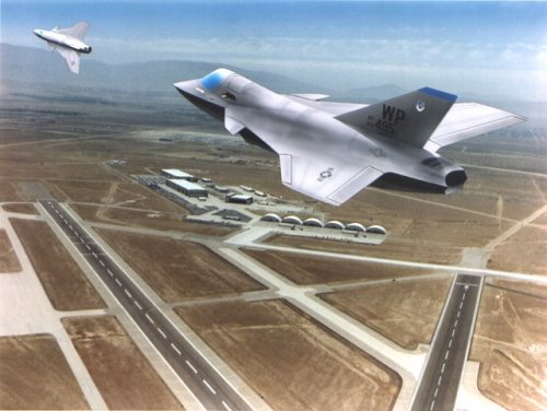
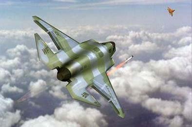
Triton said:Artist's impression of BAe Systems ASTOVL concept.
Source: http://sistemadearmas.sites.uol.com.br/ge/furt19quargeracaojsf1.html
Hesham previously identified this artist's impression as a Boeing JSF concept in the following post:
http://www.secretprojects.co.uk/forum/index.php/topic,2121.msg47124.html#msg47124
donnage99 said:i wonder what the stealth requirement back then was. With canards and 1 verticle stablizer, it should be very bad for stealth.
If I'm not wrong, the notion came from the German Lampyridae, which is a project that explored stealthy facets, but with a verticle tail. However, the verticle tail on the Lampyridae might have been a compromise for stealth to get the aircraft flyable, and there's nothing to garantee that its developers solved the problem with the RCS disadvantages of verticle tail.BAROBA said:I have read somewhere on this forum that 1 vertical stabilizer is not bad for stealthiness of a plane.
The tail can be make transparent for radar, so it doesn't reflect anything back to base.
And I imagine the same can be done for the canards.
Correct me if I am wrong,
Rob
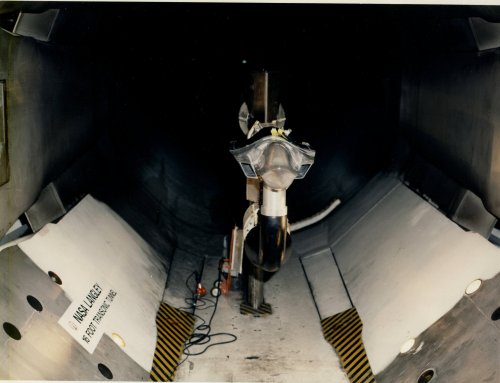
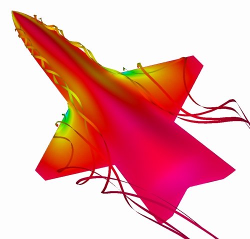
This image shows TetrUSS results from the CFD simulation of an advanced tailless fighter aircraft. Pressure coefficient contours and volume streamribbons are shown. The goal of this work was to look at various advanced control effector concepts (a control effector is any type of device that provides maneuvering control on an aircraft). Conventional (mechanical) control effectors include flaps, ailerons, elevators, and rudders.
In the Configuration Aerodynamics Branch at NASA Langley, engineers use TetrUSS to analyze and design unconventional control effector concepts: things like bumps that form on the aircraft skin, porous panels that alter surface loading, and smooth continuous control surfaces that use advanced "smart" materials. The ultimate goal is an aircraft with a continuous or fixed outer moldline, that can maneuver as well or better than an aircraft with conventional mechanical controls. The benefits are lighter weight, better performance, and positive impacts on survivability, stealth, and observability.
AeroFranz said:One of my coworkers was saying that even the best composite RF-transparent material is only 90% permeable. That's still too much reflection from the side. Anyone can confirm?
taildragger said:- actively suppress the reflection with clever devices (speculative)
donnage99 said:I've always thought that composites are bad for stealth, as it is transparent to radar, and therefore, exposing the internal structure to radar.
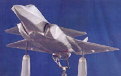
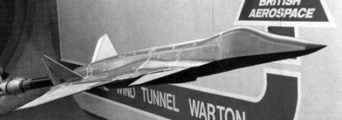
flateric said:Try these as starting point...Last pic is 9C.2 four post tail configuration very close to final V-tailed except you understand what. Note one of unique McDD/Northrop/BAe JAST design know-hows that team so hoped would help them to win - 'variable' internal weapons bay adoptable for carrying various AA/AG load depending on mission.
To my sorrow, I can't post some images from my collection due to promises I've made.
overscan said:Vectored main engine plus lift jet.
Archibald said:Which killed the project, as JAST rule was clearly A SINGLE engine for all flight phases...
Triton said:The use of the Gas Coupled Lift Fan (GCLF) was the reason why the McDonnell Douglas / British Aerospace / Northrop Grumman team was not selected by the JAST program office to enter the Concept Exploration phase of the program? It had nothing to do with the "near-tailless" design configuration being too radical?
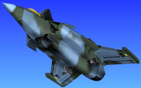
Sundog said:That's when the moved into a Lift+liftcruise engine arrangement. The Marine Corps would not accept such an arrangement.
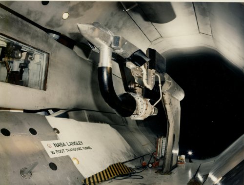
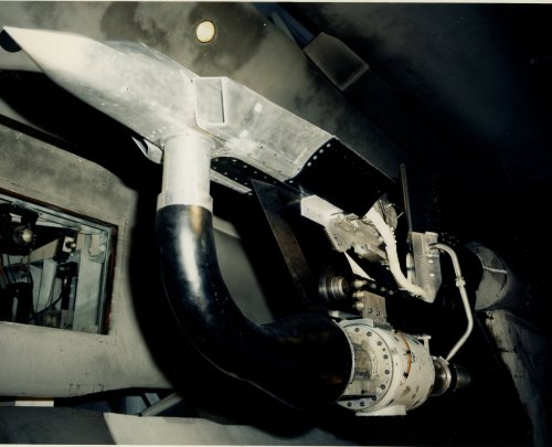
STOVL capability was designed to be provided by a “three post” [Lift + Lift/Cruise] (L+L/C) concept. While performing vertical landings and short takeoffs, the JAST 10 would have used a combination of a single GE/Allison GEA-F320L2 lift engine and an aft lift module (ALM). The ALM consisted of two principal components, a diverter valve to switch the cruise engine between STOVL mode and cruise mode configuration, and the rear lift nozzles that would have provided the thrust and control functions when the cruise engine was operating in STOVL mode and fan duct sealing during cruise mode. In STOVL mode, the diverter valve would have closed the cruise exhaust system and opened a passageway allowing the core and fan streams to enter the rear lift nozzles. The nozzles would then control the engine operating line and vectored the thrust as required for control during STOVL activities. When in cruise flight, the engine exhaust would be directed through a yaw/pitch LO axisymmetric nozzle (Y/PLON) on all three [Preferred Weapon System Concept] (PWSC) variants.
Interestingly, the MDA/NGC/BAe team believed that the separate lift engine offered the potential for a “get home” capability in the event of a main engine loss. MDA/NGC/BAe planned to demonstrate this capability during flight-testing.
Additional design features included: off-the-shelf [Pratt & Whitney] F119 cruise engine (except for the nozzle) on all variants; General Electric/Allison lift engine design of approximately 16,000 lb thrust on STOVL variant.