
You are using an out of date browser. It may not display this or other websites correctly.
You should upgrade or use an alternative browser.
You should upgrade or use an alternative browser.
Looking for histories on the F100 and F101 engine development
- Thread starter danwild6
- Start date
- Joined
- 27 December 2005
- Messages
- 16,455
- Reaction score
- 19,160
The F100 chapter in The Engines of Pratt & Whitney is pretty light on useful information, sadly.
I am pretty sure I have useful information on this subject at home, but I am on holiday until Wednesday.
I am pretty sure I have useful information on this subject at home, but I am on holiday until Wednesday.
- Joined
- 27 December 2005
- Messages
- 16,455
- Reaction score
- 19,160
The Initial Engine Development Program (IEDP) Request for Proposal (RFP) came out in mid-1968. The military’s proposal defined commonality as using the same core (the high spool), which is the more expensive engine spool from a development effort viewpoint. The Air Force and Navy engines could have different low spools. This was a cost-saving gesture in view of the escalating situation in Vietnam that was gobbling up military resources at a fierce pace.
The Air Force oversaw the engine development. The common core would be in the Air Force F100 engine with one low spool and the Navy’s F401 engine with a different low spool to provide a greater thrust level. The winner of the IEDP would develop two separate engines. The Navy’s VFX became the F-14, and shortly thereafter the Navy bowed out of the F401 engine program. This departure left the Air Force with a bigger share of the development cost, putting a strain on the Air Force’s budget.
When the IEDP RFP appeared in 1968, Allison, General Electric, and Pratt & Whitney were participating in advanced technology component programs with the Air Force Aero Propulsion Laboratory at Wright Field. The new RFP called for an 18-month demonstrator program aimed toward the air superiority fighter application, the F-15. Two contractors would be selected, and each would get about $50 million to build and test two demonstrator engines, one of which would be tested at the Air Force’s Arnold Engineering Development Laboratory (AEDC) in Tullahoma. This demonstrator program reflected the “fly before you buy” philosophy that had been used in other Department of Defense programs. Allison declined to bid, leaving General Electric and Pratt & Whitney to compete with each other.
In the meantime, the F100 team in Florida, under the direction of Gordon Titcomb, was working around the clock. The FRDC team designed what they thought the customer requested and got the first demonstrator engine to test in Florida on July 30, 1969 [3]. The second engine was delivered to the Arnold Engineering Development Center in Tullahoma (AEDC) in November 1969 for the final testing of the engine.
Source: The Engines of Pratt & Whitney by Jack ConnorsThe Air Force selected Pratt & Whitney to develop the F100 engine in early 1970. One of the reasons the military selected the company was its knowledge of inlet–engine compatibility technology and experience— lessons learned from the F-111/TF30 program
- Joined
- 27 December 2005
- Messages
- 16,455
- Reaction score
- 19,160
Source: ENGINE WARS: COMPETITION FOR U.S. FIGHTER ENGINE PRODUCTION
- Apr 68
F-15 engine RFPs to GE, P&W and Allison- Aug 68
GE and P&W selected to each built two technology demonstrators (one USAF and one USN) under 18 months contracts- Jul 69
50 hour experimental engine demonstrations (XF100)- Jan 70
P&W engine selected for F-15- Mar 70
Developmental contract award- Feb72
YF100 60-hr Preliminary Flight Readiness Test (PFRT)- Mar 72
F100 installation engine- Oct 73
F100 Qualification Test
Thomas R. Dabney & Michael J. Hirschberg
F-2
ACCESS: Top Secret
- Joined
- 22 May 2020
- Messages
- 694
- Reaction score
- 1,211
Here is some testimony on the F110 when it was still the derivative fighter engine. It seems work on making it a fighter engine goes back to at least 1976.
If memory recalls the Engine on the F-14b/d is the most F101 like and has a little less thrust then the engine on the block 30/40 F-16 being the older of the two.
F-2
ACCESS: Top Secret
- Joined
- 22 May 2020
- Messages
- 694
- Reaction score
- 1,211
https://www.rand.org/content/dam/rand/pubs/notes/2007/N3618.pdf here is a very detailed history by RAND.
F-2
ACCESS: Top Secret
- Joined
- 22 May 2020
- Messages
- 694
- Reaction score
- 1,211
by any chance do know anything about GE's FX engine proposal? I assume it wasn't related to the later F101/F110. The only thing I'm aware of is that the Air Force Evaluated PW's proposal as all around superior.Source: ENGINE WARS: COMPETITION FOR U.S. FIGHTER ENGINE PRODUCTION
- Apr 68
F-15 engine RFPs to GE, P&W and Allison- Aug 68
GE and P&W selected to each built two technology demonstrators (one USAF and one USN) under 18 months contracts- Jul 69
50 hour experimental engine demonstrations (XF100)- Jan 70
P&W engine selected for F-15- Mar 70
Developmental contract award- Feb72
YF100 60-hr Preliminary Flight Readiness Test (PFRT)- Mar 72
F100 installation engine- Oct 73
F100 Qualification Test
Thomas R. Dabney & Michael J. Hirschberg
- Joined
- 27 December 2005
- Messages
- 16,455
- Reaction score
- 19,160
It was also designated XF100. It was descended from the GE1/10 engine developed for the US / FRG VSTOL fighter.
The primary reason P & W got the contract was they were thought to be superior on engine installation and inlet compatibility after the horrible experience of the F-111 and the TF30. GE took this onboard and assigned dedicated engineers to work with the 3 AMSA contenders on engine/airframe installation during the F101 competition, and this helped them win that one.
P&W F100 then had bad issues with engine stalls, while GE F101, J101/F404 and F110 were all trouble free.
F-2
ACCESS: Top Secret
- Joined
- 22 May 2020
- Messages
- 694
- Reaction score
- 1,211
It was also designated XF100. It was descended from the GE1/10 engine developed for the US / FRG VSTOL fighter.
The primary reason P & W got the contract was they were thought to be superior on engine installation and inlet compatibility after the horrible experience of the F-111 and the TF30. GE took this onboard and assigned dedicated engineers to work with the 3 AMSA contenders on engine/airframe installation during the F101 competition, and this helped them win that one.
P&W F100 then had bad issues with engine stalls, while GE F101, J101/F404 and F110 were all trouble free.
Air Force Magazine
books.google.com
Just an add but I wonder how it differs from the F110 given that it predates the F404 and is a contemporary of the F101
Attachments


- Joined
- 27 December 2005
- Messages
- 16,455
- Reaction score
- 19,160
AWST 3 March 1969
General Electric displayed its GE1/10 augmented turbofan demonstrator engine in Washington, D.C. last week. This engine is the basis for the powerplants the company is proposing for the Navy’s F-14B and the Air Force's F-15 aircraft. The engine is approximately 143 in. long and 38 in. in diameter. It is designed to operate at turbine inlet temperatures above 2,000F.

- Joined
- 27 December 2005
- Messages
- 16,455
- Reaction score
- 19,160

XF100 demonstrator (Source: Eight Decades of Progress)
- Joined
- 15 January 2021
- Messages
- 232
- Reaction score
- 755
The F100-100 actually had good stall margin with excellent inlet compatibility with the F-15. The engine would stall from inlet distortion if the inlet ramps went off schedule due to an Air Inlet Controller malfunction, but worked well when the inlet system was functioning correctly.
Most F100-100/200 stalls were due to afterburner no-lights or sequencing blowouts. The Engine Electronic Control nozzle trim function would close the exhaust nozzle to maintain fan speed while the Unified Fuel Control would continue to advance AB fuel flow toward max Zone 5. Eventually the AB would auto light from the hot turbine exhaust, with the large AB fuel flow flame backing up against the closed nozzle. This back pressure would back up the fan duct and stall the fan, followed immediately by a high compressor stall. If the pilot retarded the throttle to Mil, the engine would normally recover with no issues, but if the throttle was left in AB, the re-light /stall / recover sequence could repeat multiple times until the compressor entered a sub idle rotating stall condition where it would not recover unless the engine was shutdown. If the engine was not shutdown from this Stall Stagnation condition, the low airflow thru the engine could result in severe turbine overheat damage.
The F100-200 engine for the F-16 extended the core airflow splitter that divides the fan discharge air between core compressor inlet and fan bypass air to close proximity to the rear face of the fan. This “prox splitter” reduced the incidence of Stall Stagnation by 95%, but did nothing to prevent the AB no-light or blow out induced stalls.
One interesting fact is the the UFC was designed with an internal solenoid that would hold the AB at zone 1 light off fuel flow, or retard the AB to that setting under the command on a AB light off detector that used UV radiation to detect the whether the AB was lite or not. The pressure pulse from a min AB auto lite was easily accommodated by the fan stall margin, the LOD would depower the UFC solenoid and the AB would be released to sequence up to Max Zone 5. However, no LOD was ever implemented on the -100/200 engines. It was an integral part of the full authority DEEC control system of the F100-220 engine.
Last edited:
- Joined
- 15 January 2021
- Messages
- 232
- Reaction score
- 755
The original development F100 engine had titanium fan and compressor disks in all 13 stages of compression (3 fan, 10 high compressor). They learned the hard way that under the high compression ratio design of the engine of 25:1, the high pressures and temperatures at the back end of the high compressor set the conditions for self sustaining titanium fire, or as we in the propulsion community like to call it - a rapid oxidation event. While the compressor exit conditions did not initiate a titanium fire, any hot spark or excessive rub from a broken blade or other unusual condition could start the fire, and the high partial pressure of oxygen in the back of the compressor would propagate to the entire high compressor. For those who have never witnessed a Ti fire, once it starts it is like magnesium. During at least one test in an altitude test cell, the Ti fire initiated and all that was left following the event was the motor mounts.
Subsequently, the high compressor was redesigned with Nickel disks, blades, stators, and cases in the rear 7 stages of the high compressor, with the weight of the engine increasing from around 2900 lbs to 3050 lbs. This philosophy of nickel aft stages has carried forward in the F100-229 and F119/F135 high compressors.
Subsequently, the high compressor was redesigned with Nickel disks, blades, stators, and cases in the rear 7 stages of the high compressor, with the weight of the engine increasing from around 2900 lbs to 3050 lbs. This philosophy of nickel aft stages has carried forward in the F100-229 and F119/F135 high compressors.
- Joined
- 15 January 2021
- Messages
- 232
- Reaction score
- 755
Interesting that the GE1/10 demonstrator appears to have two stages of variable vanes in the fan module, both inlet guide vanes and between the 1st and 2nd stage of the fan. This may have been for data gathering, determining what the optimum angle of the 1st to 2nd stage vanes, or whether variable vanes were even needed in a multistage fan of this pressure ratio. F100, F101, F110, F404, F119, and F135 only have variable inlet guide vanes, and the RB199 and EJ100 dispense with inlet guide vanes entirely.AWST 3 March 1969View attachment 684421
General Electric displayed its GE1/10 augmented turbofan demonstrator engine in Washington, D.C. last week. This engine is the basis for the powerplants the company is proposing for the Navy’s F-14B and the Air Force's F-15 aircraft. The engine is approximately 143 in. long and 38 in. in diameter. It is designed to operate at turbine inlet temperatures above 2,000F.
- Joined
- 15 January 2021
- Messages
- 232
- Reaction score
- 755
One of the lessons that P&W learned early in the fielding of the F100 engine was that the high thrust to weight ratio of the F-15 and F-16 resulted in the pilots using the engine differently than had been expected. Compared to the F-4, the high available thrust resulted in the pilots pulling the throttles back toward idle much more often to slow down to corner velocity instead of leaving the throttles at Mil or Max during combat maneuvers. This transition from high power to low power, back to high power many times during the flight greatly accelerated the low cycle fatigue accumulation on the engine components and shortened the time on wing. This drove the use of engine cycles instead of hours as the primary life tracking for module and component life. The -100/-200 engines had a Events History Recorder (EHR) that counted the number of Mil to Idle to Mil "LCF" cycles, and the crew chief added the number of "Manual" cycles that represented Shutdown to Mil to Shutdown cycles, typically one per flight. The module life limit was set by the number of Total Calculated Cycles (TCY) = Manual Cycles + 0.25 (LCF cycles - Manual Cycles). The Manual Cycles were subtracted from the LCF cycles because the EHR counted both as a LCF cycle).
The ratio of 4 LCF cycles = 1 Manual cycle was empirically derived from the average real life mission, representing average damage to the engine components. Different components of the engine being affected differently by cyclic damage, with static parts like a diffuser case being a pressure vessel are virtually unaffected by engine shutdown, while the majority of fatigue damage to compressor and turbine rotors is down at shutdown. During engine operation, the thick bores of compressor and turbine rotor are being cooled for bleed air, while the rim are relatively hot. This results in the rotor rims being in compression, despite the high centrifugal speeds. The LCF cycles produce varying compressive loads, which does produce fatigue damage, but engine shutdown result in the thin rims cooling rapidly while the thick bores are still hot, putting the rims in tension which tries to pull open any fatigue cracks, which can make 10 times the life debit as the operating compressive cycles.
Initially, the F100 core was limited to 900 TCY. Improvements to turbine blade coatings and materials increased this depot overhaul life to 1350 TCY, and eventually to 1800 TCY. Development of the F100-220 engine produced the Increase Life Core, with a wear resistance HPC variable vane actuation system, improved combustor design, redesigned turbine disks, single crystal multi-pass turbine blades & vanes, stiffer #4 bearing support to reduce HPT blade tip rub, and a oil damped #3 bearing support to eliminate excessive compressor blade tip rub during bowed rotor engine starts. This updates produced a core module of 4000 TCY between depot overhaul, with the changes incorporated into earlier core modules during overhaul and used for -100, -200 and -220E engines when the engine fleet was upgraded to the -220 "equivilent" configuration.
- Joined
- 15 January 2021
- Messages
- 232
- Reaction score
- 755
During the late 1970s and early 1980s, with the increasing use of finite element analysis and greater computing power, P&W and the other OEMS began getting better at predicting Low Cycle Fatigue (LCF) damage on life limited parts. Initially, they would recommend an entire population of part when statistical analysis indicated when one part in a 1000 (B.1 life) would have developed a detectable crack.
As the 1980s progressed, improved analysis tools and material analysis resulted in designing life limited parts to be damage tolerant. The design life of the part, such as a compressor or turbine disk, was calculated assuming that the part had already developed a shallow fatigue crack (usually defined as 0.050" deep), with this pre-flawed part being able to safely continue in service over an entire depot overhaul period. Large efforts were made to develop high sensitivity fluorescent penetrant, eddy current probes, and automated inspection scan plans to detect any small cracks during depot overhaul, and if no cracks were detected the part can continue in service for another overhaul period, at which time the part would be inspected again, or retired if the overall published life limit of the part would be exceeded during that next scheduled depot interval. These LCF crack inspections became more and more critical as the depot inspection interval of the F100 modules was extended toward 4000 TCY and beyond. Current activity being worked with the OEMS and the Air Force Propulsion Directorate is moving from deterministic life analysis to probabilistic life analysis that will enable the individual components to remain in service essentially forever as long as they pass the depot level crack inspections.
One very interesting crack inspection technique that was developed for the original F100-100/200/220 fan disks that were eventually cleared to a 3000 TCY interval was a process called cryogenic spin. This inspection utilized a characteristic of the fan disk Ti alloy to become very brittle and notch sensitive at cryogenic temperatures. At depot, there were multiple spin pits built where the fan disk was mounted to an arbor, weighted fan blade simulators were installed in the disk slots, and the whole assembly was cooled with liquid nitrogen and spun at high speed. IF there were any fatigue cracks initiated in the disk, they would immediately propagate and the disk would explode, sending shrapnel into the lead brick lining of the pit. If there were no defects, the cryo spin would leave beneficial residual compressive stresses in the rim of the disk, actually making it stronger. While effective, each time this inspection found a flaw, the spin pit required significant repair before the next disk could be inspected. This technique was not used in later design disks in -220 4000 cycle fan module nor the -229 4300 cycle fan module disks.
- Joined
- 15 January 2021
- Messages
- 232
- Reaction score
- 755
When the F100-100/200 engines were first fielded in the F-15 and F-16, their Main Fuel Pump (MFP) was variable displacement vane pump with an inlet centrifugal boost stage feeding the vane section, and a second centrifugal boost stage in parallel that was clutch engaged to feed the separate augmentor fuel pump (AFP) when AB was selected. The high pressure vane section consisted of a slotted rotor with hard carbide vanes that floated in the slots, surrounded by two interlocking semicircular blocks that moved in and out to vary the output flow. The flow setting was varied to maintain a constant 60 psi differential across the metering valve within the Unified Fuel Control (UFC).
This MFP, manufactured by Chandler Evans (CECO), was the most unreliable component on the engine, with multiple failure modes, almost all of which resulted the carbide vanes broken into little pieces and engine flameout. There was pump cavitation, vane tilting, and others. One failure occurred when the pump was installed with a shipping O-ring, used to protect the MFP mount flange, instead of proper engine O-ring. The oversized shipping O-ring got caught between the gearbox and MFP flange, causing the pump to run mis-aligned and wearing out the drive splines in short order. Lesson learned - never use shipping O-rings that are different than the Bill of Material.
Many fixes were incorporated into the CECO MFP to address the known failure modes. However, when P&W statisticians plotted the known failures events and causes against all MFP failures using Weibull analysis, there appeared to be at least 3 more failure modes that were predicted, but of unknown cause.
This convinced the USAF to fund P&W to develop a replacement fixed displacement gear type fuel pump that incorporated all of the lessons learned with the CECO van pump. It also got rid of the clutched AB boost pump, using just one centrifugal inlet boost pump for both main and AB fuel flows. Since it was a fixed displacement pump, they also had to develop a separate bypass valve that would maintain the constant delta-P across the UFC metering valve by bypassing extra fuel back to the inlet of the pump. This new MFP and Bypass valve were heavier and less efficient (more heat generation) than the vane MFP, but was 100% reliable in use.
The F100-220 and -229 also use this gear MFP, but incorporate the variable bypass function within their Mail Fuel Control that replaced the -100/-200 UFC.
- Joined
- 15 January 2021
- Messages
- 232
- Reaction score
- 755
Keeping the lubricating oil of a jet engine cool (typically below 300F) is a design challenge. The F100 was born with 4 air to oil heat exchangers in the fan bypass air duct, plus a fuel cooled oil cooler. The challenge is in the upper left corner of the flight envelope, the fuel burn flow is not enough to cool the oil, but the fan discharge air is cool. At supersonic speeds, fuel flow is high but the fan discharge air is hotter than the oil.
The prototype F100 engines had thermostatic shutters that blocked off the fan discharge air when it was hotter than the oil. These were shutters were deleted from the production engines, but the fuel/oil cooler had a second section that utilized AB fuel flow to help cool the oil at high speeds where the fan duct coolers were heating the oil.
When the F100-220 was developed in the mid 1980s, engine lubricating oils had improved and could run hotter for longer without breaking down and coking. For the -220, two of the air-oil coolers were removed (less supersonic heating), and the fuel oil cooler lost its AB fuel section while the core fuel burn section was made larger (less cooling supersonic in AB). This did result in higher oil temperature in the upper left corner, but this was acceptable with the latest specification oils.
For the -229 engine, higher fan pressure ratio resulted in even higher fan bypass air temperatures, and the fan duct air-oil coolers were deleted entirely. Being a higher thrust engine, the core fuel flows increased through the fuel oil cooler under most conditions, and oil temperatures remained acceptable.
Very interesting! One thing that always bugged me is that US jets did not seem to have airframe-external air/oil heat-exchangers (and as you write, later engines indeed do not!) while European ones did. Even the Typhoon and Rafale still have what I think are air/oil heat-exchangers on the bottom of the engine bays.
Also interesting that they did not bypass the fan duct heat-exchangers on the oil side at high Mach, which intuitively seems like the obvious thing to do. But then that requires some kind of actuated valve (with associated failure modes) while the production solution does not (correct me if I'm wrong), so clever idea.
Did supercruise in any way make oil thermal management more challenging in the F119? With the F100-PW-220 & -229 the AB fuel cooling loop was already gone, but then supersonic flight in a F-15 or F-16 is a comparatively transient affair. If the -229 oil cooling system partially relied on never reaching thermal steady state in the top right corner, the F119 would've likely required a re-think?
- Joined
- 15 January 2021
- Messages
- 232
- Reaction score
- 755
You are right, the F100 did not bypass the oil around the air/oil coolers. In addition to the additional failure modes this type of valve system could have introduced, you also have the problem of stagnant oil trapped inside the cooler. This trapped oil could get cooked and coked in place under the high temperature supersonic fan duct air flow conditions, while blocking the airflow as in the original design reduced the heat transfer while constantly moving oil thru the coolers.Very interesting! One thing that always bugged me is that US jets did not seem to have airframe-external air/oil heat-exchangers (and as you write, later engines indeed do not!) while European ones did. Even the Typhoon and Rafale still have what I think are air/oil heat-exchangers on the bottom of the engine bays.
Also interesting that they did not bypass the fan duct heat-exchangers on the oil side at high Mach, which intuitively seems like the obvious thing to do. But then that requires some kind of actuated valve (with associated failure modes) while the production solution does not (correct me if I'm wrong), so clever idea.
Did supercruise in any way make oil thermal management more challenging in the F119? With the F100-PW-220 & -229 the AB fuel cooling loop was already gone, but then supersonic flight in a F-15 or F-16 is a comparatively transient affair. If the -229 oil cooling system partially relied on never reaching thermal steady state in the top right corner, the F119 would've likely required a re-think?
For the -229, the most challenging oil cooling is not the upper right, but in the upper left corner of the envelope where inlet air is -60F, core fuel flows are low due to the low ambient air pressure, and there are no air / oil coolers available to utilize the relatively cool fan bypass air.
Although we are drifting from the subject of this thread, the F119 does not have a problem cooling oil under supercruise conditions. It does have a relatively conventional fuel / oil heat exchanger with the oil being cooled by the core engine fuel flow, which is relatively high under supercruise conditions. The F119 does have another trick where in addition to the core engine burn fuel flow, it can also modulate a Thermal Recirculation valve in Main Fuel Throttle Valve (MFTV) control to increase the total flow rate from the airframe, through the engine fuel / oil cooler, and recirculate the excess flow back to the airframe fuel tanks. This thermal recirculation flow rate is controlled by the engine FADECs in response to engine oil temperature, engine fuel temperature at the main combustor fuel nozzles, or a request from the airframe to increase flow through its system of fuel cooled heat exchangers (ECS, Hydraulics, etc) as needed for cooling. This recirculated fuel passes through the Air Cooled Fuel Cooler (ACFC) that utilizes ram air from the inlet boundary air diverter duct to cool the fuel before it returns to the fuel tanks. The most challenging condition is on the ground after flight when there is no ram air and the fuel tank levels are low, reducing the thermal mass of the fuel. Under these conditions, the APU is started and APU bleed air powers an ejector that pulls air thru the ACFCs and other actions are automatically taken to reduce the airframe heat load when Thermal Management Mode (TMM) is activated by the pilot.
- Joined
- 15 January 2021
- Messages
- 232
- Reaction score
- 755
In all jet engines that I am familiar with, they keep their lubrication oil within each bearing compartment by surrounding the compartment with buffer air bled from the compressor, with this buffer air leaking (slowly) into the bearing compartment thru a seal system, typically either a carbon seal or a labyrinth seal. Air leaking in keeps the oil from leaking out. This air leakage into the bearing compartments is dumped overboard as breather air.
On the F100, the #2/#3 bearing compartment breathes directly into the gearbox around the vertical towershaft that mechanically connects the high compressor shaft with the gearbox geartrain. However, the #1, #4, and #5 bearing compartments breather air is returned to the oil tank by the compartment scavenge pumps. This air / oil mixture enters the oil tank, where it passes through a deaerator that drops the oil to the bottom of the tank where it is delivered to the oil pump, and the air is released to the top of the tank where an internal tube provides a passage to the gearbox, and the combined breather flow exits the engine thru a pressure regulating breather valve and out the side of the aircraft.
When the USAF Thunderbirds air demonstration team first started flying the F-16 with the F100-200 engine, the oil tank bulged and ruptured during their inverted inverted and right wing low knife edge passes. It turns out that the oil tank breather air tube became submerged in oil under these conditions and the breather air within the tank became pressurized during these extended flight demonstration condition beyond the tank pressure capabilities.
The fix was to divide the breather air line from the oil tank to the gearbox into two legs - the original line in the top of the oil tank, and a second path that extended above the static oil level in the tank (to prevent any siphon action) and then down toward the bottom of the tank. During inverted operation with the oil in the top of the tank, this second breather line allowed the breather air to flow unimpeded to the gearbox and overboard. This modification was only accomplished on the F100-200 engines used by the Thunderbirds, but became the standard configuration for Ff100-220, 220E, and -229 engines.
BTW - when the F100 is inverted and the oil moves to the top of the oil tank, oil pressure drops to zero with no oil being supplied to the engine bearing compartments. No damage will occur if this condition is restricted to 30 seconds or less (Dash-1 restriction), although there have been F100 engines that have run with zero oil pressure (for other reasons) for many minutes without damage. The F110 engine has not been as forgiving for zero oil pressure events, with main shaft bearing failing quickly without oil supply.
- Joined
- 15 January 2021
- Messages
- 232
- Reaction score
- 755
F100 Control System
The original F100-PW-100 control system consisted of the hydromechanical Unified Fuel Control (UFC) and the supervisory Electronic Engine Control (EEC). The UFC controlled all of the basic control functions for the engine including receiving the mechanical throttle input from the pilot, controlling fuel flow to the main combustor, opening and closing the core compressor start bleed, controlling the angle of the Rear Compressor Variable Vanes (RCVV) on the core compressor, controlling the fuel flow and zone sequencing of the 5 zone augmentor, and the base positioning of the exhaust nozzle convergent area (Aj). The EEC scheduled the vane angle of the fan Compressor Inlet Variable Vanes (CIVV), trimming fuel flow to the main combustor to meet core rotor speed (N2) and Fan Turbine Inlet Temperature (FTIT) targets, enabled the UFC Idle Area Reset schedule to open the exhaust nozzle at Idle when the landing gear handle was in the down position, and trimmed nozzle position at Mil power and above to control low rotor speed (N1) to a scheduled rpm.
Part 1 - Unified Fuel Control
The UFC throttle input was called Power Lever Angle (PLA) - 0 degrees was cutoff, 15 was Idle, 86 was Mil power, 91 was minimum zone 1 AB, and 130 degrees was zone 5 maximum AB. The UFC had an internal rate limited throttle shaft called Power Lever Angle Prime (PLAP). Regardless of PLA angle, PLAP was limited to 15 degrees until the starting engine had achieved Idle speed. Once at Idle, PLAP would follow the PLA request up to Mil power. When AB was selected, PLAP remained at Mil until N2 speed reached scheduled Mil speed, then would be released to 91 degrees to initiate AB and then sequence up to zone 5 as requested.
Inputs to the UFC were throttle position, a hydromechanical flyweight N2 speed sensor mounted on the main fuel pump, a helium filled capillary tube hydromechanical sensor that measured Fan discharge temperature (Tt2.5), main combustor burner pressure (Pb), and push – pull cable feedback for the RCVV angle and nozzle position. Main combustor fuel flow for starting and Idle to Mil power was scheduled based on N2 and Pb, biased by TT2.5. Start bleed closure was based on N2 reaching near Idle speeds, RCVV vane angle was scheduled by N2 and Tt2.5 which are the parameters needed to calculate corrected compressor rotor speed. When trimming the engine, there were adjustment screws on the bottom of the UFC to set EEC Off Idle N2 speed, Mil power N2 speed, and RCVV position, all based on lookup tables in the engine Technical Order (T.O.) manual.
The F100 had 5 zones of afterburner. The sprayrings are oval in cross section, with many holes pointing inward across the exhaust flow, with a pointed rod secured to the opposite side of the tube and protruding thru the hole. This pintel rod mostly closed off the opening in the sprayring. When fuel pressure increased inside the sprayring, the oval tube would flex toward round, drawing the pintel rod away from the hole, creating a variable area spray port, small at low flow and bigger at high flow, maintaining a good spray pattern over a wide range of fuel flows. Each pintel rod was threaded at its base, and the spray patterns of each pintel a sprayring was manually adjusted at depot and then brazed in place to maintain that flow. Zone 1 sprayring discharges into the circular gutter area of the flameholder in the core airflow discharge and keeping this area burning is needed to keep all of the other zones flame lit. Zone 2 was just outboard of Zone 1, still in the core flow. Zone 3 was the first sprayring in the fan duct flow, then Zone 4 (three rings) in the inner area of the core flow, and Zone 5 was the outermost ring in the fan duct flow.
The UFC had just one AB fuel flow metering valve, with each zone having an On-Off valve, and there was a splitter valve that changed the balance of flow going to the Core sprayrings (Zones 1, 2, & 4) and Fan duct sprayring (Zone 3 & 5), biased by Tt2.5. The volume of the sprayrings dictated the use of a Quick Fill system that would fill each sprayring with fuel, and then based on increasing fuel back pressure, would then connect the sprayring to the metered flow. If this Quick Fill system did not work correctly, all of the metered flow would divert to the empty sprayring and starve Zone 1, putting the AB flame out. When PLA was advanced into AB, PLAP would advance to 91 degrees and hold at minimum zone 1, Quick Fill and metered fuel flow would enter the sprayring and AB ignition would be turned on for approximately 1-2 seconds. With the AB assumed to be lit, PLAP would ramp up to Maximum Zone 1 and hold, then Zone 2 Quick Fill turned on. When Zone 2 indicated full, Quick Fill is turned off and the metered AB flow would then be divided between Zone 1 and 2. This clockwork process repeated with each Zone requested until Max Zone 5 fuel flow was achieved. The AB fuel flow was scheduled by the UFC metering valve based on Pb and Tt2.5 inputs, and there was a trim screw that adjusted the Max AB fuel flow based on T.O. lookup tables.
Last edited:
- Joined
- 15 January 2021
- Messages
- 232
- Reaction score
- 755
F100 Control System
Part 2 - Electronic Engine Control
The F100 EEC was an early digital computer that provided supervisory scheduling and limit adjustment to those parameters controlled by the UFC. It built on the experience of the manual cockpit fuel flow EGT trimmer used on the SR-71/J58 and the automatic fuel flow EGT trimmer used on the F-111F / TF30-PW-100/111. The F100 engine would operate normally from start, Idle to Mil, and to Max AB with the ECC turned off using a switch in the cockpit, but with lower performance and fewer protections.
The EEC inputs were inlet temperature (Tt2), N1 Fan speed, CIVV angle feedback, N2 core speed, FTIT, PLAP, and Pb (the latter two from resolvers inside the UFC). Outputs were accomplished via solenoids and stepper motors.
The CIVV vanes are positioned at -30 degree (cambered) with the EEC off, reducing Fan airflow. With the EEC on, the CIVV remain at -30 until 90% corrected N1, then ramping to 0 degrees (full axial) as the speed increased to 104% corrected N1, at which time the engine was flowing its maximum rated corrected airflow of approximately 225 pounds per second and the engine delivering rated Mil and Max thrust (corrected for inlet pressure).
At Mil power and above, the EEC can trim core fuel flow to achieve a desired N2 speed (cold day) and limit FTIT (hot day). During the initial engine acceleration to Mil power or above after engine start, the engine would accelerate to the UFC Mil power setting, and then the EEC would typically trim the fuel flow up to reach the N2 target or FTIT limit. Subsequent accels to Mil or AB would hit the previous EEC trim and then be adjusted up or down to the newest target that may change as the aircraft moves about the flight envelope.
At Mil and above, the EEC could trim Aj from the UFC setting up or down to achieve the desired N1 speed (open nozzle increases N1, closed nozzle decreases N1). The EEC nozzle trim authority was 100%, able to close the nozzle fully closed to control N1 speed even if the UFC has the nozzle open for Max AB fuel flow (for example, if the AB fire had blown out).
During engine trim, the EEC was fed a false Tt2 signal of -7F, which set a N1 speed of 100.7% (104% corrected to -7F). Using the T.O. lookup table, the N2 speed was adjusted using a trim screw on the EEC to achieve the desired Engine Pressure Ratio (EPR) for the inlet temperature of the day. Increasing N2 would drive N1 up, which the EEC returned back to 100.7% N1 by trimming the nozzle closed, which increased EPR. Once this cold day N1 / N2 ratio was set, the FTIT limit was set using another EEC trim adjustment that set the number of “clicks” necessary for engine thrust performance. On a really healthy engine, the minimum was 5 clicks. As the engine deteriorated over time, the click setting could go up to 11, raising the FTIT temperature limit to maintain hot day performance.
When the engine was running on the FTIT limit, the EEC calculated a delta N2 that represented how far below the engine was running below the N2 schedule set during the false Tt2 trim. For every delta N2, there was a corresponding delta N1, where the EEC trimmed the nozzle to lower N1 speed below the 104% corrected cold day setting. This trimming was supposed to maintain EPR at the optimum level for performance and stall margin as the engine was running against the FTIT limit.
As the engine high pressure turbine deteriorated with time (primarily due to increasing tip clearances), the N2 would tend to slow down, with more energy passing to the low pressure turbine which tended to increase N1 speed. The EEC had a correction factor that looked at FTIT vs N2 to determine the level of deterioration and would automatically adjust its N1 speed targets to compensate.
When the F-15s were first stationed in Alaska, they began to experience AB initiation stalls on takeoff. It was determined that under really cold conditions, the UFC Mil power trim was higher than the EEC targets. On the first accel, the UFC Mil N2 was overshooting the EEC targets, with the EEC cranking the nozzle closed to keep N1 under control before it could unwind the UFC core fuel flows. During this N2 overshoot, the EPR would go too far above target just as the AB lit, resulting in the Fan stall. When this phenomenon became known, P&W developed “Arctic Trim”, which lowered the UFC Mil setting to prevent this overshoot.
Later, it was determined that the UFC Mil power trim setting would creep upward over time as the turbine deteriorated, and eventually the EPR overshoot could occur during non-Arctic conditions. “Arctic Trim” then became standard T.O. procedure for all F100-PW-100/200 engine trim actions. It had long been observed that AB takeoff stalls seemed to peak in the spring and fall with the temperature change, with only minor adjustments found during EEC trim and troubleshooting operation. No one had observed the regular UFC Mil power trim adjustment and made the connections to the EPR overshoot phenomena.
Last edited:
- Joined
- 15 January 2021
- Messages
- 232
- Reaction score
- 755
F100 Control System
Part 3 - Back Up Control
For single engine safety in the F-16, the F100-PW-200 was equipped with a Back Up Control (BUC) to enable the pilot to continue to operate the engine if there was a failure of the Unified Fuel Control (UFC). The only inputs to the BUC were the mechanical throttle input, fan duct pressure for altitude bias, and a separate push / pull cable for rear compressor variable vane position feedback. The BUC did not know engine speed, inlet temperature, or turbine temperature.
When the pilot decided that BUC operation was needed, he was directed to first place the throttle at mid-range if the engine was running, or in cutoff if the engine had flamed out. BUC was then selected via a cockpit switch, which depowered a transfer solenoid in the BUC, allowing fuel pressure to move a valve that transferred core fuel flow from the UFC to the BUC. That same fuel pressure was ported to the Variable Geometry Transfer Valve (VGTV) which switched control of the RCVV and Start Bleed from the UPC to the BUC, and closed off the 13th stage bleed air supply to the Convergent Engine Nozzle Control (CENC). Throttle input position (PLA) directly modulated core fuel flow and RCVV position.
Instead of an automatic start sequence in the UFC initiated by moving the throttle from cutoff to the 15 degree Idle position, a new Idle detent was electrically activated in the cockpit throttle at 41 degrees PLA. When the pilot moved the throttle from cutoff to 15 degrees, the BUC output light off fuel flow only. Once the pilot received an indication of engine light-off with increasing RPM and FTIT, he was then supposed to slowly advance the throttle over a 30-40 second period from 15 degrees PLA to the BUC Idle stop of 41 degrees, mimicking the N2 and FTIT rise seen during a normal engine start. When the throttle reached the Idle position, the high compressor start bleed closed. The pilot was then restricted to advancing or retarding the throttle between the 41 degree Idle and 86 degree Mil setting with no less than 5 seconds between Idle and Mil power settings, directly controlling core fuel flow and RCVV vane position. The F100 exhaust nozzle is a balance beam construction, with exhaust pressure on the balance segments and the area of the convergent segment forward of the pivot air loading the nozzle in the closed position. With the bleed air muscle pressure shut off to the CENC, the nozzle would close to minimum Aj as exhaust pressure increased with the slow throttle advance.
The BUC was a very simple control that afforded get home capability, but it had several drawbacks:
- It was highly dependent on pilot throttle technique during a high work load event - the engine was not responding properly to pilot input. If the throttle was moved too fast during start or from Idle to Mil, the engine would stall and overtemp with no protections.
- Thrust was limited at Mil power, and might not be enough to climb if performing a heavyweight takeoff. The permissible flight envelope was very limited for proper BUC operation.
- Advancing the throttle into AB was prohibited. If AB was selected, the UFC would still turn on AB fuel and ignition and sequence up to Zone 5 if requested. With the exhaust nozzle fully closed, this would result in immediate stall and turbine overtemp with no protections.
- It was discovered that if the pilot started advancing the throttle too soon toward Idle after light-off FTIT indication, the engine could still accelerate while being about 10% N2 below the normal start trace. Once throttle reached BUC Idle and the start bleed closed, the engine immediately stalled and stagnated, requiring the pilot to shut the engine down again to reattempt the start. The Dash-1 and maintenance manuals were changed to direct the operator to wait until N2 rpm stabilized after light off before starting the advance toward the Idle detent.
- Joined
- 15 January 2021
- Messages
- 232
- Reaction score
- 755
F100 High Compressor Variable Geometry
The F100-100/200/220 high pressure or rear compressor (HPC) consists of 10 stages of blades and stators, with an approximate pressure ratio at Mil power of 8:1. The Rear Compressor Variable Vanes (RCVV) system has variable stator vanes at the inlet of the HPC, and the 4th and 5th stage stators. These vanes control the airflow angle of attack to the 4th, 5th, and 6th stages blades, reducing the core airflow at low rotor speeds to maintain stall margin, and increasing airflow at high rotor speeds for performance and efficiency. At the 7th stage stators, there is an annular start bleed that dumps excess air that cannot be processed through the aft stages of the HPC during sub-idle operation, which is closed off by a scissor linkage actuated strap at Idle and above.
The RCVV are scheduled by the UFC from -41 degrees (low power) to +4 degrees (high power) based on temperature corrected core rotor speed. Later on, the low power position was increased to -35 degrees by changing the RCVV hydraulic actuator stop when it was found that this improved air starting of the engine. The UFC hydromechanically calculated corrected core rotor speed (N2C2.5) using the N2 speed sensor and the T2.5 temperature sensor, which is the inlet temperature of the HPC. While corrected speed of the core at Idle would only slightly lower than the indicated N2 at around 9000 rpm, at high power the 325F fan discharge temperature resulted in a N2 C2.5 of approximately 10, 400 vs the indicated N2 of 12,800.
During engine trim, there was a check band where the RCVV angle was compared to corrected N2 at multiple speed points from Idle to Mil. However, there was a very narrow trim band that RCVV vane able had to be within limits over a small speed range just below Mil power, and the RCVV trim screw was adjusted to put ensure the RCVV was inside the trim band, while also staying inside the check band over the full Idle to Mil checks.
What was not obvious from the RCVV trim checks was that at high Mach numbers with elevated ram inlet temps (240F at 40K, M2.0 standard day) and T2.5 temperatures in the 450F range, the RCVV schedule shifted significantly more axial to help maintain core airflow and engine thrust when the core became rotor speed limited. This high Mach, high T2.5 schedule was an extension of the trim box set point to lower N2C2.5 speeds outside the check band, running the HPC blades at a higher angle of attack and much closer to the axial flutter boundary of the blades, which could break HPC blades in high cycle fatigue within a few seconds if exceeded.
When running on the low T2.5 schedule, the RCVV moved quickly cambered when the throttle was reduced, with plenty of margin away from HPC axial flutter. The EEC would prevent the UFC PLAP from being retarded below Mil power when above Mach 1.4. This was stated in the Dash-1 to prevent inlet instability (buzz) at high Mach numbers. However, this EEC limiter also prevented the core from decelerating when the RCVV were running to their high T2.5 aggressive schedule, where any reduction in N2 speed could immediately put the HPC blades into axial flutter. Flight beyond the Dash-1 low altitude speed limit of 800 KCAS (1.2 Mn at sea level) can put the engine at risk if the throttle was reduced below Mil since the EEC protection is limited when below 1.4 Mn.
Any RCVV binding, looseness or assembly error impacted engine performance and operability. An individual vane out of position due to mis-assembly or a vane arm retention bolt falling out would result in HPC blade failure. Uniball bearing wear in the drive linkage and sync rings, and spline wear in the cross fan duct drive shaft caused slop in the system with the vanes being further and further from their intended position. Complete redesign of the system in the F100-PW-220, and at least partially retrofit into the -100/-20/-220E fleet provided significant wear & corrosion reduction, foolproof assembly, and damage tolerant features that virtually eliminated RCVV vane mis-position from the F100 engine
Actually, as a result of the stalls due to the afterburner, a task force was established at Pratt & Whitney. As a result they came up with a detection system to detect the hot afterburner gases flowing up the duct into the fan system, and that with some other engine parameters were developed into a stall detection for the electronic engine control. The electronic engine control would then automatically retard the power lever to military power while simultaneously scheduling the exhaust nozzle to open someone to relieve the back pressure on the fan. This resulted in essentially eliminating the engine from going into stall stagnation, and was done before the proximate splitter was incorporated.The original development F100 engine had titanium fan and compressor disks in all 13 stages of compression (3 fan, 10 high compressor). They learned the hard way that under the high compression ratio design of the engine of 25:1, the high pressures and temperatures at the back end of the high compressor set the conditions for self sustaining titanium fire, or as we in the propulsion community like to call it - a rapid oxidation event. While the compressor exit conditions did not initiate a titanium fire, any hot spark or excessive rub from a broken blade or other unusual condition could start the fire, and the high partial pressure of oxygen in the back of the compressor would propagate to the entire high compressor. For those who have never witnessed a Ti fire, once it starts it is like magnesium. During at least one test in an altitude test cell, the Ti fire initiated and all that was left following the event was the motor mounts.
Subsequently, the high compressor was redesigned with Nickel disks, blades, stators, and cases in the rear 7 stages of the high compressor, with the weight of the engine increasing from around 2900 lbs to 3050 lbs. This philosophy of nickel aft stages has carried forward in the F100-229 and F119/F135 high compressors.
- Joined
- 15 January 2021
- Messages
- 232
- Reaction score
- 755
That is correct, but it was after the fact stall recovery. When the fan stalls, the hot high pressure air in the tailpipe reverses direction momentarily and actually exits forward through the fan. If you are in the correct viewing location, you can actually see a momentary flame belch forward of the fan. Once this high pressure is relieved, the flow immediately recovers in the aft direction and the fireball is swallowed up by the engine. During the stall flow reversal, airflow through the engine drops significantly resulting in a rapid drop in main combustor pressure and increasing turbine temperature. The EEC senses the rapidly increasing inlet temperature and falling burner pressure as a stall, and activates the solenoid that retarded the internal throttle to Min Zone 1 AB along with some other strategies to recover from the stall and prevent turbine overtemp.
The Light Off Detector, if it had been implemented on the -100/-200 engine, would have addressed one of the major causes of AB induced stalls as a preventative measure.
The Light Off Detector, if it had been implemented on the -100/-200 engine, would have addressed one of the major causes of AB induced stalls as a preventative measure.
- Joined
- 27 December 2005
- Messages
- 16,455
- Reaction score
- 19,160
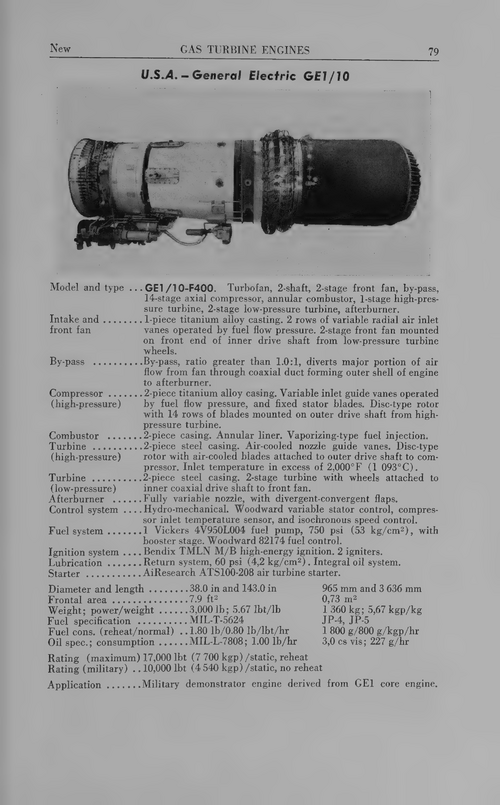
- Joined
- 15 January 2021
- Messages
- 232
- Reaction score
- 755
I believe the F101 was a direct development from the GE1/10 demonstrator. I didn’t realize how much smaller the demonstrator engine was. Interesting that the high compressor was 14 stages, while the production F101/F110/CFM56 compressor was only 9 stages.GE1/10 details from Aircraft Engines of the World 1970 by Paul H Wilkinson.
Similar threads
-

-
 Eight Decades of Progress - A Heritage of Aircraft Turbine Technology (1980)
- Started by overscan (PaulMM)
- Replies: 6
-
-
Looking for info on Starstreak/ Stormer or AESP 2350-T-110-201
- Started by Shirazz
- Replies: 0
-
Query - Early interwar italian fighter design
- Started by palg
- Replies: 2