Kramer X-4 Air-To-Air Missile

Actually, the Artemis was about as simple as you could get. The seeker head rotated while the rocket projectile was unrotated. It used a very simple receiver circuit that ran through a Wheatstone bridge-like circuit that determined the seeker position relative to the reflected signal of the radar painting the target. This worked similarly to a conical scan radar signal being received. This completed a signal that caused a solenoid to pop the spoiler up when the direction of the signal matched the direction of the spoiler.
When the seeker was on target, you got a zero reference that resulted in no output.

The problem with this system is that it's very crude in terms of input and output. The whole idea behind it was to used the missile only in a tail chase and it would be fired pretty much directly at the target. The seeker device was simply to correct relatively minor deviations in course to keep it moving at the target. It was better than nothing, but not by much.

With the X-4, the guidance system was limited to a very simple one by the small size of the missile. That ruled out using active radar or even semi-active homing or beam riding. Those circuits required tubes and those took up a lot of space. You can get some idea of how much space such systems took at the time from that of the Bat glide bomb:

bat-3-jpg.544253


The homing radar is up front. On top of the wings is the guidance system. Behind that is the gyros and battery. Not a small system. Something similar was used in the US JB-3 Tiamat. That missile is several times larger and heavier than the X-4 because of the necessary room to fit all those electronics.
 
This is not simple at all! Let alone, that you need a plane with radar (I believe, only some night fighters were equped with that). On this picture I see almost the entire rocket stuffed with electronic components and as you said, the missile had to be extra large for all this expensive and complex components. How can you call that simple?

The X-4 had some simple electric components but hardly anything which could be called electronic (maybe an amplifier for the proximity fuse). Just four solenoids for the four fins and maybe an electric motor (not sure about that) to spin up the gyro. This are all very simple and cheap components. The small size is not a disadvantge, as you described it) but the result of simple elegant design which will easily carry enough explosives to destroy a bomber.

The Germans could have never afforded using radar in anti aircraft rockets! Despite that the Artemis with all the mass of expensive component seemed to be a more or less a complete failure.
 
Last edited:
This is not simple at all! Let alone, that you need a plane with radar (I believe, only some night fighters were equped with that). On this picture I see almost the entire rocket stuffed with electronic components and as you said, the missile had to be extra large for all this expensive and complex components. How can you call that simple?

The X-4 had some simple electric components but hardly anything which could be called electronic (maybe an amplifier for the proximity fuse). Just four solenoids for the four fins and maybe an electric motor (not sure about that) to spin up the gyro. This are all very simple and cheap components. The small size is not a disadvantge, as you described it) but the result of simple elegant design which will easily carry enough explosives to destroy a bomber.

The Germans could have never afforded using radar in anti aircraft rockets! Despite that the Artemis with all the mass of expensive component seemed to be a more or less a complete failure.
That is for an autonomous, active radar homing system. A semi-active system is somewhat simpler but still fairly complex and requires some electronics (eg., vacuum tubes). The Artemis system would have required four very simple antenna circuits using nothing more than simple capacitors, resistors, and maybe, maybe a crystal to demodulate the signal. The output circuit compares the inputs, again not a complex issue to do and then causes the solenoid to either activate or remain unactivated.

The X-4 circuitry was like that. It's just resistors and capacitors and a couple of diodes. Plain coils for the two solenoids select the output by moving a set of contacts. The diodes provide a half wave to operate the solenoids--quasi-AC if you will. In total it's like a couple of resistors, capacitors, diodes, and coils with contactors. It's on or off. With no need for an antenna or demodulating a signal it's extremely simple. Artemis would add a few more caps and resistors for each antenna, but otherwise it's just about as simple.

The problem with the X-4 system is that it is very coarse being all-or-nothing. Artemis would have been similar. That gives you no fine control over the missile, instead making only rough course corrections. When you are talking about a pilot flying a single seat fighter and having to control that plane which is only marginally stable--a desirable situation for a fighter so it maneuvers well--and trying to aim using nothing but a simple gunsight at a spec in the sky at a distance, while trying to watch a missile he can barely see, and all the time trying to maneuver that missile to the spec in the sky, it just won't work.

Artemis wouldn't have worked much better, if at all, than an unguided barrage of rockets, any more than X-4 was any real improvement over the R4M. For a workable guided missile you need a good guidance system that is fast reacting, accurate, and can make graduated course adjustments. In 1945, nobody had such a system in place.

Engineers had some idea what a system like that needed to be in 1945, but they didn't have a working example of one at that time.

Probably the first ones that really worked well were used with early SAMs where the missile and target were tracked by radar and an analog computer calculated the missile trajectory to an impact while the missile was controlled from the ground by a radio command circuit.

The US and Germans both had such systems in design by late 1944 and into 1945, but it would be 1947 to 48 before any of these--the first working one is almost certainly the one used with Nike Ajax--were viable. That system took an analog computer designed by Western Electric and Reeves Electronics the size of several large file cabinets to work.
 
2 the Artemis fell out of range of the rc system, so wires could have helped a lot...
Sigh. It have no radio control system! "Artemis" was a HOMING missile. It was supposed to automatically home on radar echo from target. I.e. the close it to the target, the more accurate guidance would be (while X-4 would actually suffer decrease in accuracy with distance from carrier plane).

3. Spining bodies are automatically gyro stabilized. The gyro itself was for the reference, this is clear.
Yeah, so at least now you understood why your suggestion that "Artemis would benefit from gyro" make no sence?

4. The Artemis was full of expansive electronic features and was underpowered, this was propable the reason, why it didnt contain a gyro. So it was uncontrolable. Here, you really needed a fast reaction time, because in the first two seconds the Artemis was not
controlable at all!
The "expansive" electronic equipment of Artemis would be a very simple dish antenna, amplifying circuit (most likely single-tube), a relay and one solenoid.

this was propable the reason, why it didnt contain a gyro.
For your information, the Sidewinder did not contain the gyro too. The reason is, that mechanical gyros are very expensive and relatively bulky.

A gyro is a simple mechanical device, most parts can be made out of steel (exept the driving engine). At that time, a radar system could have easily been more expensive than 100 steel disks dynos... The proplem with the dyno is the additional weight which the underpowerd heavy Artemis couldnt carry.
Sigh. Gyro required precise machining and to get the information from the gyro you need the sensor input.
 
The Sidewinder used rollerons not gyros and the original version used just 17 vacuum tubes for its guidance system.


With the Artemis, all you needed was one antenna offset such that it worked like a nutated feed. The antenna rotates off the boresight of the seeker head. As it rotates, it works like the receiver on a conical scan radar. The strongest signal is the one that activates the spoiler to change the missile's direction. A very simple receiver circuit.
 
Please explain your calculation, they dont make any sense to me. Maybe you could provide a scetch an explain when exatly the fast reaction time would have been needed.

In any air combat you are facing the same problem with moving targets. but with active steering and a proximity fuse, hitting the target will become much much easier. Keep in mid, you need to hit exactly a week spot with guns!
Okay.

The whole point of MCLOS guidance is that operator (by remote control commands) is trying to keep the missile on the imaginary line connecting the operator's sight and the target. If missile deviates from line of sight, or target moves, operator send the command to guide the missile back to the line of sight.

The problem in using MCLOS for air-to-air combat is that nothing here is stable. The fighter plane is constantly moving. The target is constantly moving independent of fighter. So the line of sight is constnantly moving also - movig unpredictably and irregularly. And to spice things up - the missile is also moving not perfectly.

This all sums up into the situation, when - from the operator point of view - the target is constantly moving in the sight, thus forcing to constantly adjust, and the missile is dancing madly around the line of sight. And the worst thing? The further the missile is from operator, the less and less precisely operator could determine how far from the line of sight it really is. So the best operator could do, is to make missile slowly spiral around the line of sight, not moving too far from the center. And with such missile as X-4 - without proportional rudder control - operator could not even made fine adjusments required for missile to stay on straight line. He could only jerk missile from side to side, making it move a zig-zagging line, overcoming its spin-stabilization. Which is actually an additional problem, because you could not just temporarely switch off the spin stabilization like you do with gyro one. The operator is forced to overcame the azimuth/altitude stabilization by action of rudders, which means that missile isn't exactly easy to turn around.
 
Hi T. A.,

The problem with the X-4 system is that it is very coarse being all-or-nothing. Artemis would have been similar. That gives you no fine control over the missile, instead making only rough course corrections.

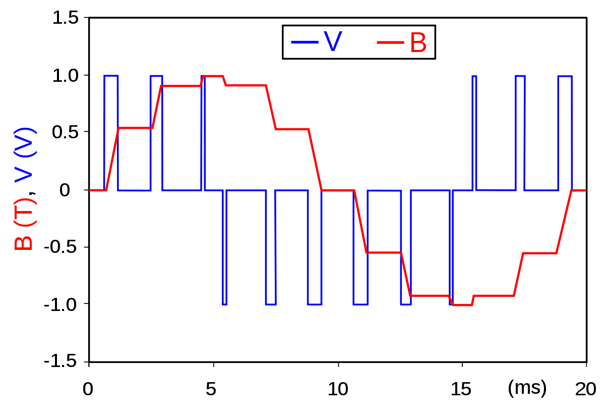
Actually, in the case of the X-4, you have to differentiate between control surface deflection, which was in fact all-or-nothing due to the use of solenoids, and operator control, which gave proportional input and translated it into pulse width modulation (PWM) signals.

"Neutral" input gave equal time for full-up and full-down (respectively full-left and full-right) deflection, and with increasing deviation from the neutral point, the control for the desired direction would be deflected an increasing proportion of the time, so the overall control effect would in fact be proportional.

At least, that's how I understood the video linked above :)

Regards,

Henning (HoHun)
 
I have no time for a detailed answer, but this is not true, please take a look on the video. The rotating drum for the control have different sections for changing the upwards/downwards lenth. They are showen in several steps in the video. In the real X-4 this was almost certainly a angled seperation instead of steps allowing continously control changes.

Edit: Henning, you are right, I have overseen the last part on my phone...
 
Last edited:
"Neutral" input gave equal time for full-up and full-down (respectively full-left and full-right) deflection, and with increasing deviation from the neutral point, the control for the desired direction would be deflected an increasing proportion of the time, so the overall control effect would in fact be proportional.
That's exactly the way it worked.
 
Hi T. A.,

The problem with the X-4 system is that it is very coarse being all-or-nothing. Artemis would have been similar. That gives you no fine control over the missile, instead making only rough course corrections.

Actually, in the case of the X-4, you have to differentiate between control surface deflection, which was in fact all-or-nothing due to the use of solenoids, and operator control, which gave proportional input and translated it into pulse width modulation (PWM) signals.

"Neutral" input gave equal time for full-up and full-down (respectively full-left and full-right) deflection, and with increasing deviation from the neutral point, the control for the desired direction would be deflected an increasing proportion of the time, so the overall control effect would in fact be proportional.

At least, that's how I understood the video linked above :)

Regards,

Henning (HoHun)
"Vibrate" would be a better word. It doesn't change that the system was very coarse in terms of control. Also, you could only input one signal at a time, either up / down or roll / turn. Thus in it's short flight time the operator had to try to correct for height and angle off along with try to estimate any parallax error and guide the missile to an intercept predicting where the plane would be when the missile arrived, not where the target currently is. It would be no different than deflection shooting other than firing the missile from dead astern of the target at the same exact altitude.

Deflection shooting for most pilots was a difficult thing to do with a reflector gunsight. Many would correct their lead watching tracer fire into the target. An experienced pilot who knew how to deflection shoot and had trained on it might manage the correct angle off, but by 1944 the average Luftwaffe pilot was completely unskilled in this area. That would only make even trying to get the X-4 to the target harder.
 
Hi T. A.,

It doesn't change that the system was very coarse in terms of control.

I'm not sure what you mean with "coarse in terms of control". It's an analogue proportional control system, which means that a minute deflection of the joystick will yield, over the course of one rotation of the missile, a minute change of differential control force application, and a large deflection will yield a large change of differential force application.

Also, you could only input one signal at a time, either up / down or roll / turn.

Hm, what's your source on that? According to the video linked above, the joystick input was encoded electronically as polarity changes for one axis and as power changes for the other one. That would allow simultaneous control of both axes. As the missile continuously rotated by design, there was no roll axis control of course, just an azimuth control.

Regards,

Henning (HoHun)
There is no "minute" deflection of the joystick. Either you make contact and transmit a signal or you don't. It's all or nothing. You can't cause say a 50% deflection.

30987062469.jpg


Pocock goes into great detail how these systems work including giving electrical schematics of the systems. Figure 10 on pg 63 shows how the Düsseldorf-Detmold system for the X-4 worked. It is incredibly simple. You move the joystick to complete the circuit, either positive or negative 200 VDC and that is transmitted down the wire to the control circuit in the missile. A pair of diodes that are opposed let the signal flow to one of two solenoids that determine the direction of deflection.

Because the input voltage is DC, the coil deflects fully and stays that way until the joystick is moved and the circuit is opened. The gyro is a zero reference for the missile end to correct for the rolled position.
 
The only thing which is true, is, it is totally simple. Basicalls, it it a PWM signsl (pulse width modulation) which allows a quasi continously operation
 
Hi T. A.,

There is no "minute" deflection of the joystick. Either you make contact and transmit a signal or you don't. It's all or nothing. You can't cause say a 50% deflection.

I presume you saw the video linked above? It shows an analogue joystick that moves a contact over an encoding drum that either makes contact or doesn't, in time intervals determined by the proportion of joystick deflection. Proportional control is not achieved by finely modulating the output voltage, but by finely modulating the time period either one of two output voltages is provided.

If Pocock shows the system to work differently, then we are probably talking about different systems, but the Waffen-Revue article linked in this thread also disagrees with one of your (Pocock-based, I guess) statements, and that's the one about control being one-axis (at a time) only. The relavant quote from the Waffen-Revue is attributed to the contemporary "Baubeschreibung" document, dated to February 1944:

"The wire-transmitted commands, which have distinctly different nature, are separated by two telegraphic relays of the same type, boosted, and conducted directly via to the tail surfaces via the commutator of the attitude gyro which serves to stabilize control."

(My translation ... might sound a little more confusing in English than in does in German, but I tried to favour accuracy over style ;-)

Relays are usually associated with pure on/off switching, but again, pulse width modulation is a technique that achieves proportional values by varying the ratio between the periods a switch is on or off.

These relays are effectively PWM decoders, and the joystick position is transmitted in PWM-encoded form.

Of course, I haven't seen Pocock's figure 10 on page 63 ... maybe he's showing something different altogether, so I can only comment on the video linked above and the Waffen-Revue article.

Regards,

Henning (HoHun)
 
The only thing which is true, is, it is totally simple. Basicalls, it it a PWM signsl (pulse width modulation) which allows a quasi continously operation
On the X-4 it is simply a + / - 200VDC signal that isn't modulated at all. Only the radio versions use a carrier wave and modulation (AM). The X-4 system being wire connected relies on the positive or negative signal transmitted on one or the other wire using DC. That way there is no crosstalk between the wires and the 200 volt strength is necessary due to the distance and use of small gage steel wire having relatively high resistance.
 
The puls length between positivecand negative current van be varried continously variable, thuscenabeling a smooth control.every 90 degree you can send another ratio of positive/negative relation which determins the resulting impact on the direction.
 
The resistance of 22 ga copper wire at altitude would be about 14 to 15 ohm per 1000 feet. Steel wire would likely be about triple that. The other issue to some degree would be the insulation breakdown at altitude. As you go higher, insulation values fall off rapidly. I'm sure the Germans would have accounted for that choosing a voltage that wouldn't penetrate the insulation while being high enough to send the signal to the missile successfully. But you have to consider this.
 
Altitude doesnt affect the conductivity or insulation
Yes, it does. You'd know this if you ever worked on aircraft electrical systems and wiring.


Electrical-conductivity-as-a-function-of-altitude-reproduced-from-Hale-1984.png


In fact, one of the first aircraft manufacturers to really recognize just how bad this problem was is Boeing. They were an early entry into high-altitude flight with planes like their Stratocruiser and the B-17. They had to come up with totally new insulation systems for wiring because of it.

Temperature, likewise changes conductivity / resistance. As temperature drops, resistance drops with it. When it's 50 below at say 10,000 meters, resistance is much lower than at 25 degrees and 1000 meters.
 
Hi T. A.,

On the X-4 it is simply a + / - 200VDC signal that isn't modulated at all.

A "signal that isn't modulated at all" is not a signal, but a power supply ;-)

The X-4 system being wire connected relies on the positive or negative signal transmitted on one or the other wire using DC.

I'm a bit confused about the implications of this statement. There's just one transmission circuit, so the control system can't use just one or the other wire, can it?

the 200 volt strength is necessary due to the distance and use of small gage steel wire having relatively high resistance.

Does Pocock show a time diagram of the resulting signal? PWM works by switching between two discrete (maximum) voltages, encoding the desired proportional control effect as ratio of the periods each of the two discrete voltages is applied. Switching between the two descrete values is described in the video linked above as "polarity change".

PWM works with (temporarily) constant voltage just fine, and is entirely suitable for transmitting proportinal control inputs. Considering that the Waffen-Revue quotes primary, contemporary documentation, it almost sounds to me as if Pocock might be misunderstanding some aspects of the technology involved.

With regard to the operation voltage, the contemporary "Baubeschreibung" notes: "Due to the low wire resistance of the 'X-4', it's possible to operate with a very low transmitter voltage and thus use the small joystick 'Knirps' ['Midget'], currently under development for the 'Fritz-X', directly as transmission device, by which means the transmitter and receiver are reduced to the simplest possible technologies." As this implies the Fritz-X was operating with higher voltages, obviously insulation would have been less of a problem on the X-4 than it might have been on the Fritz-X. Not sure why you brought this up, actually ... does Pocock have anything to say on this?

Regards,

Henning (HoHun)
 
Altitude doesnt affect the conductivity or insulation
Yes, it does. You'd know this if you ever worked on aircraft electrical systems and wiring.


Electrical-conductivity-as-a-function-of-altitude-reproduced-from-Hale-1984.png


In fact, one of the first aircraft manufacturers to really recognize just how bad this problem was is Boeing. They were an early entry into high-altitude flight with planes like their Stratocruiser and the B-17. They had to come up with totally new insulation systems for wiring because of it.

Temperature, likewise changes conductivity / resistance. As temperature drops, resistance drops with it. When it's 50 below at say 10,000 meters, resistance is much lower than at 25 degrees and 1000 meters.

Those altitudes are out of the range for the X-4. The altitude itself doesn't have any influence on the conductivity but the temperature has. I guess, the control signals were anyway transmittet by a relais to the solenoids, so that the cables were only used for signaling, but not for the power supply. Since the X-4 was controlled by a PWM signal, a loss in voltage wouldn't have any affect in the controls of the rocket.

By the way, the X-4 might have been one of the first application of PWM signals, which have been quite unusual in an analog time, does anybody have other early applications of that in mind?
 
Last edited:
2 the Artemis fell out of range of the rc system, so wires could have helped a lot...
Sigh. It have no radio control system! "Artemis" was a HOMING missile. It was supposed to automatically home on radar echo from target. I.e. the close it to the target, the more accurate guidance would be (while X-4 would actually suffer decrease in accuracy with distance from carrier plane).

3. Spining bodies are automatically gyro stabilized. The gyro itself was for the reference, this is clear.
Yeah, so at least now you understood why your suggestion that "Artemis would benefit from gyro" make no sence?

4. The Artemis was full of expansive electronic features and was underpowered, this was propable the reason, why it didnt contain a gyro. So it was uncontrolable. Here, you really needed a fast reaction time, because in the first two seconds the Artemis was not
controlable at all!
The "expansive" electronic equipment of Artemis would be a very simple dish antenna, amplifying circuit (most likely single-tube), a relay and one solenoid.

this was propable the reason, why it didnt contain a gyro.
For your information, the Sidewinder did not contain the gyro too. The reason is, that mechanical gyros are very expensive and relatively bulky.

A gyro is a simple mechanical device, most parts can be made out of steel (exept the driving engine). At that time, a radar system could have easily been more expensive than 100 steel disks dynos... The proplem with the dyno is the additional weight which the underpowerd heavy Artemis couldnt carry.
Sigh. Gyro required precise machining and to get the information from the gyro you need the sensor input.
Artemis needed to be manually steered in the second phase of the flight (the first two seconds were completely uncontrolable which made it extremly difficult) before it started homing. Any kind of gyro stabilisation would have been very helpful! So it was an uncontrolable barrel without any use!

As said before, the equipment of the Artemis was everything but simple, the rocket had three times the size of the x-4 and was almost completely filled with complex electonics, which made it underpowerd by the way...

The Sidwinder used four gyros to control the flaps, a very clever system which wasn't invented back than. Here, the gyros are also very simple devices which are powered by the air stream.

A gyro only needs precise mashining and a low friction bearing structure when it is used for navigation (see the V1), but here it is only needed to run for less than 30 s and is only used as a reference for up and down (keeping the switch plate in position). There is no high demand in extreme turning speeds, super precise orientation or longlivity. Its just a small simple metal disk with, I guess, an electric starter engine.
 
Last edited:
The Fritz-x and X-4 might have been the first true PWM applications. I took a look into Wikipedia (couldn't find anything else in the moment...) and despite the variable intake length in steam engines, there is no application mentioned before 1946:


When the control system was designed, they might not even have noticed, that this might have been a groundbreaking invention. Of course, chances are high, that there have been other example before (I don't count the variable intake length as a valid PWM modulation).
 
When the control system was designed, they might not even have noticed, that this might have been a groundbreaking invention. Of course, chances are high, that there have been other example before (I don't count the variable intake length as a valid PWM modulation
Er... its literally one of the most commonly used system of proportional control during WW2. For example, USAAF's Felix IR guided bomb used a pulse-width modulation in each scan to guide itself toward target.
 
Still, proportional control of guided bombs, idenpendantly which ever came first (surly not Felix), might have been one of the first application.
 
Still, proportional control of guided bombs, idenpendantly which ever came first (surly not Felix), might have been one of the first application.
I think the first were the fire control systems on warships, probably.
Agreed. The first such systems were fire controls where the turrets on a ship were automatically trained on a target and tracked it by the fire control system rather than the crew in the turret. This was repeatedly miniaturized during the war to the extent possible and applied elsewhere. Some examples of such systems--far in advance of anything the Germans produced-- would include the SCR 584 radar fire control system for M2 90mm guns, or the fire control system on a B-29.

The SCR 584 - M2 system saw the gun mounts powered with a gasoline driven generator on mount, automatic fuze setting, and power ramming. The mounts in automatic were driven by the fire control computer rather than the crew using 'follow the pointer' and manually doing all of that at the mount.
 
Hi Dilandu,

Er... its literally one of the most commonly used system of proportional control during WW2. For example, USAAF's Felix IR guided bomb used a pulse-width modulation in each scan to guide itself toward target.

So are we all on the same page at least that the X-4 did indeed use proportional control?

In the meantime, I also found a mention in an article by Wolfgang-D. Schröer ("Lenkkörper und Zielweisungsgeräte der Deutschen Luftwaffe, Teil I, Mechanik und Funk-Fernlenkung von Fall- und Gleitbomben") which mentions that the rotating-drum version of the missile control stick was the Gb 203a, while later a Gb 203b was developed that eliminated the rums in favour of potentiometers ... which in turn lead to the miniaturized "Knirps" version which used the same technology.

Schröer also quotes a relevant comment by Kramer on the Fritz-X - of course, it also applies to the solenoid-actuated controls of the X-4:

"When the spoiler follows the varying pulses at sufficient frequency so that the inertia of the missile only permits the pulses to take effect according to their average, a simple yes-no control with full deflection has become, in the final result, a virtually proportional control without requiring any more effort."

("Folgt der Unterbrecher diesen wechselnden Impulsen mit ausreichender Frequenz, so daß die Trägheit des Flugkörpers die Impulse nur in ihrem Mittelwert zur Wirkung gelangen läßt, so ist aus einer einfachen Ja-Nein-Steuerung mit vollen Ausschlägen ein im praktischen Endeffekt stetige Steuerung geworden, ohne daß irgendwelcher Mehraufwand erforderlich war.")

This video shows the rotating-drum style joystick in operation ... it's a bit like controlling the missile with a coffee grinder, judging by the sound! :-D

View: https://www.youtube.com/watch?v=ALtdaBgo8JE&t=462s


(Timestamp 462 s)

Regards,

Henning (HoHun)
 
Except the X-4 Dusseldorf / Detmold system is not an copy of the Kehl Strassboug system shown in the video.

0573f62a803d35a6c07b52ce2083ee56.jpg


It's much simplified compared to it. A major reason for that is both the missile and controlling aircraft have less room to take a complex system.
 
Hi T. A.,

Except the X-4 Dusseldorf / Detmold system is not an copy of the Kehl Strassboug system shown in the video.

But you're aware that the picture you posted shows a "Knirps" stick, which was used with the X-4 as well as with the Fritz-X?

In the meantime, I also found a mention in an article by Wolfgang-D. Schröer ("Lenkkörper und Zielweisungsgeräte der Deutschen Luftwaffe, Teil I, Mechanik und Funk-Fernlenkung von Fall- und Gleitbomben") which mentions that the rotating-drum version of the missile control stick was the Gb 203a, while later a Gb 203b was developed that eliminated the rums in favour of potentiometers ... which in turn lead to the miniaturized "Knirps" version which used the same technology.

I posted this up specifically because you wrote:

There is no "minute" deflection of the joystick. Either you make contact and transmit a signal or you don't. It's all or nothing.

Quite clearly, Schröer describes a proportional control system based on potentiometer inputs, which was also applicable to the X-4.

So if you meant to state that the joystick is of a digital type that only records the direction of the deflection and not its size, I would say that everything I have been able to find seems to disagree with that statement.

If you meant to state that the joystick allows analogue input, but the signal is converted into discrete voltages afterwards, that actually jives with what I read, but it's, as I think should have become clear by now, in no way an indication that the system was incapable of proportional control.

Of course, if you could share Pocock's description of that joystick, we might be able to narrow down the source of the contradiction more closely.

Regards,

Henning (HoHun)
But they aren't the same system. Dusseldorf-Detmold only has the 200 VDC circuit in it. It's all-or-nothing. There is no need for a stepped variable wave in the circuit. One reason for this was to allow it to be mass produced by semi-skilled and unskilled workers. Because of the wire guidance, you can't use an AC or modulated signal as this would create cross-talk on the wires. That's why a pure DC signal is used instead.
 
Hi T. A.,

There is no "minute" deflection of the joystick. Either you make contact and transmit a signal or you don't. It's all or nothing.

I think you still haven't clarified whether you think that the Knirps joystick is a purely digital input device or not.

Schröer states it's an analogue input device using potentiometer inputs. Do you disagree with him?

It's all-or-nothing.

You are aware that PWM is a common method to use "all-or-nothing" (discrete DC voltages) for proportional control?

Maybe Pocock's book has a different explanation of how the X-4 works that is more accurate than the original German Baubeschreibung quoted in the Waffen-Revue? I'm not sure the design was ever frozen for production - but it's pretty clear that the German documents describe a system based on proportional control.

Regards,

Henning (HoHun)
It isn't necessary here. Where you use discrete voltages are in stepper motors. A solenoid is either on or off. It's 100% or nothing. A solenoid won't pull halfway or whatever. Once you overcome the no input position, it moves in the direction of the applied voltage to its limit. Thus, for a 200 VDC + / - system you don't need proportional control.

If you are using a modulated AC radio signal, then you can input a proportional signal and get a graduated output assuming you are using servos like the Fritz X and Hs 293 have.
 
Hi again,

You are aware that PWM is a common method to use "all-or-nothing" (discrete DC voltages) for proportional control?

Well, I just found the following paragraph in OP 1666, German Explosive Ordnance, Volume 1, dated 11 June 1946:

GENERAL DESCRIPTION. The X-4 is a fin-stabilized guided missile with a proximity fuzed warhead developed specifically for use by fighter planes against enemy bomber formations. [...]

[...]

Steering is effected by means of rake spoilers located in the tail fins. These spoilers vibrate at a rate of 5 cycles per second, control being effected by making the period during which the spoiler projects from one side longer than that during which it projects from the other. When the two periods are equal, no control is applied. This method of steering has the disadvantages of appreciable drag and a certain amount of delay, but has the advantage of simplicity and instantaneous mechanical response.

[...]

The receiving unit in the missile is quite simple consisting primarily of a polarized relay for azimuth control and unpolarized marginal relay for elevation control. The polarized relay responds only to polarity changes in the direction of the current flow through the wires while the unpolarized marginal relay responds only to changes in the value of the current, regardless of its polarity. In this way, both azimuth and elevation control signals can be transmitted simultaneously over the same pair of wires.

The relays are connected to the spoiler solenoids in the tail fins, through the gyro commutator system. This arrangement converts the left-right and up-down signals into the proper pulses which are to be fed to the solenoids actuating the spoilers. The power supply is a small 9-volt dry battery located in the afterbody of the missile.

During the flight tests, there were no detrimental effects from static electrical charges accumulating on the wires and the mechanical difficulties had been solved by paying out the wire from the bobbins on the missile and similar bobbins on the parent plane simultaneously. Wire control was selected primarily because, compared to radio remote control, it is practically jamproof.

(Full document available at https://archive.org/details/OP1666GermanExplosiveOrdnanceVolume1/page/n218/mode/2up )

So both the assertion that proportional control wasn't possible and the assertion that only one axis could be controlled (at a time, or whatever) don't agree with the US Navy Bureau of Ordnance's post-war description.

Regards,

Henning (HoHun)
 
Hi T. A.,

Where you use discrete voltages are in stepper motors. A solenoid is either on or off. It's 100% or nothing. A solenoid won't pull halfway or whatever. Once you overcome the no input position, it moves in the direction of the applied voltage to its limit. Thus, for a 200 VDC + / - system you don't need proportional control.

Maybe it's just a misunderstanding of the term "proportional control" then? What I meant is that you deflect the joystick by a minute deflection, and then the missile responds with a minute course change in the desired direction. If you deflect the joystick by a large deflection, the missile responds with a coarse course change.

I didn't mean to suggest that this was encoded as proportional voltage ... in a PWM system, the control signal is encoded as the duty cycle.

Regards,

Henning (HoHun)
 
Hi again,

You are aware that PWM is a common method to use "all-or-nothing" (discrete DC voltages) for proportional control?

Well, I just found the following paragraph in OP 1666, German Explosive Ordnance, Volume 1, dated 11 June 1946:

GENERAL DESCRIPTION. The X-4 is a fin-stabilized guided missile with a proximity fuzed warhead developed specifically for use by fighter planes against enemy bomber formations. [...]

[...]

Steering is effected by means of rake spoilers located in the tail fins. These spoilers vibrate at a rate of 5 cycles per second, control being effected by making the period during which the spoiler projects from one side longer than that during which it projects from the other. When the two periods are equal, no control is applied. This method of steering has the disadvantages of appreciable drag and a certain amount of delay, but has the advantage of simplicity and instantaneous mechanical response.

[...]

The receiving unit in the missile is quite simple consisting primarily of a polarized relay for azimuth control and unpolarized marginal relay for elevation control. The polarized relay responds only to polarity changes in the direction of the current flow through the wires while the unpolarized marginal relay responds only to changes in the value of the current, regardless of its polarity. In this way, both azimuth and elevation control signals can be transmitted simultaneously over the same pair of wires.

The relays are connected to the spoiler solenoids in the tail fins, through the gyro commutator system. This arrangement converts the left-right and up-down signals into the proper pulses which are to be fed to the solenoids actuating the spoilers. The power supply is a small 9-volt dry battery located in the afterbody of the missile.

During the flight tests, there were no detrimental effects from static electrical charges accumulating on the wires and the mechanical difficulties had been solved by paying out the wire from the bobbins on the missile and similar bobbins on the parent plane simultaneously. Wire control was selected primarily because, compared to radio remote control, it is practically jamproof.

(Full document available at https://archive.org/details/OP1666GermanExplosiveOrdnanceVolume1/page/n218/mode/2up )

So both the assertion that proportional control wasn't possible and the assertion that only one axis could be controlled (at a time, or whatever) don't agree with the US Navy Bureau of Ordnance's post-war description.

Regards,

Henning (HoHun)
I'll agree with the second, two axis control, but not with the first. You can't deflect a solenoid half way. It's on or it's off. That doesn't preclude rapidly banging it on and off, but you can't get partial deflection because solenoids don't work that way.
 
A solenoid need suffiecient time to get from one end position the other. If the PWM signal is fast enough, it will never flip from one extreme postion to the other, instead it will wobble around the desired postition and enable precise control.
 
I think you still haven't clarified whether you think that the Knirps joystick is a purely digital input device or not.
...What? Digital input device? What the holy kitten are you talking about?!

Digital input device is the one that code the input into a combination of digits - 0-1, for binary systems. The Knrips joystick was a purely analogue device!
 
Hi Dilandu,

Digital input device is the one that code the input into a combination of digits - 0-1, for binary systems. The Knrips joystick was a purely analogue device!

Agreed! :) I was trying to find a phrase that describes a joystick that just has one switch per direction (two per axis) ... that would 2 bit per axis, sort of. But I think we have excluded this one already, anyway!

Regards,

Henning (HoHun)
 
It is something in between of digital and analog. The trigger timing is fixed, the voltage has no influence on the control which is typically digital, but the pulse lenght can vary continously, which is analog.
 
Back
Top Bottom