- Joined
- 11 June 2014
- Messages
- 1,333
- Reaction score
- 1,780
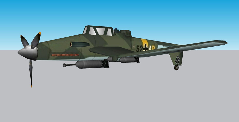
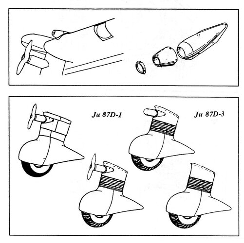
If the entire tail (fin, stabilizer) would rotate 180 degrees along the fuselage's longitudinal axis, what was the stabilizers' camouflaged upper surface in takeoff configuration would become the camouflaged lower surface in in-flight configuration. Looking at the model images, I can see camouflaged stabilizer upper surfaces in both configurations. The modelmaker may have made two different tails for one model, or two different models altogether. I think both are unlikely.
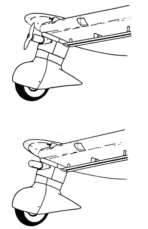
The in-flight configuration in 620.jpg shows the fin's upper edge at a slight upward angle with the stabilizer's lower surface, the takeoff configuration in 617.jpg and 618.jpg shows the fin's upper edge at a distinctly bigger upward angle with the stabilizer's lower surface. That bigger upward angle would translate to a bigger downward angle if the entire tail would rotate 180 degrees along the fuselage's longitudinal axis.. That's not what 619.jpg and 620.jpg show.
If all four images show the same model, the modelmaker hinged the fin to rotate ~90 degrees downward to show the in-flight configuration.
I think it is likely the model's translation from takeoff to in-flight configuration matched the one chosen for the Ju 187's design.
Yes, it's an upwards and downwards movement of the fin by about 90-degrees. Not a 180-degree rotation of the whole tail assembly.


")

.jpg")

 de-perspectived.jpg")