
Thanks to my wallet - from a binder scans that I have tried to clean up and condense the image to get more detail into the 1200 pixel limit.
Section 1 Subsonic VTOL aircraft with single B.S. Pegasus engine
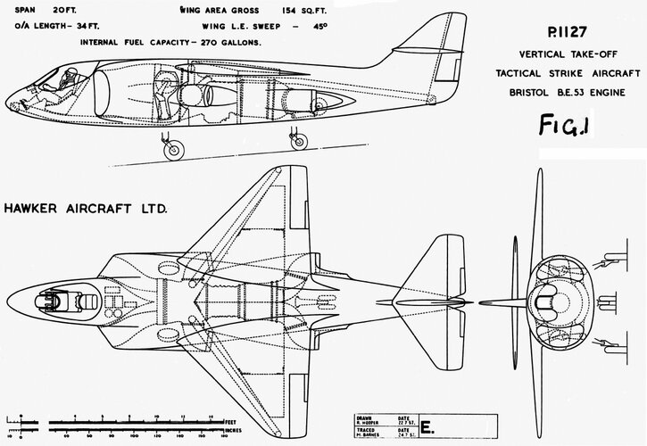
Fig 1.1 Original P.1127 layout.
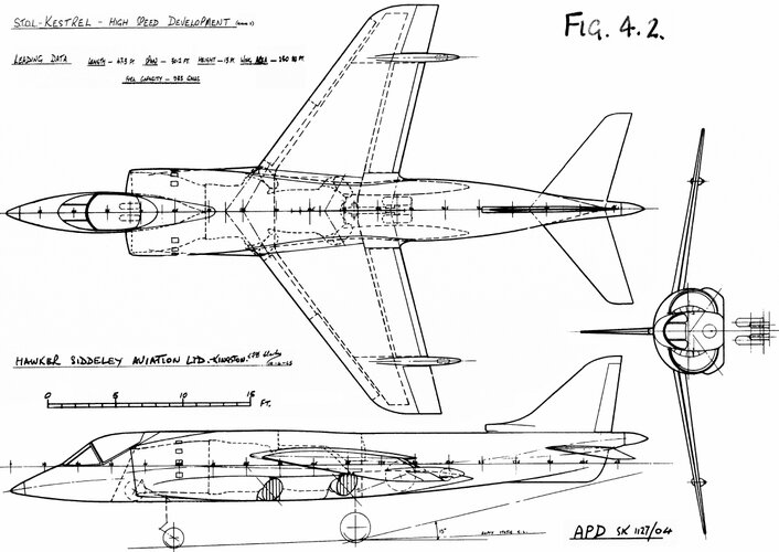
The straight through hot end is a feature which is currently being studied for supersonic STOL projects.
Fig 1.2 First Four Nozzle layout.
Fig 1.3 First Layout with Tri-cycle U/C.
The problem of the best undercarriage position is one that is still present in current projects. This particular layout was fairly simple but put the main wheels in a hot area when down and occupied a very useful fuel area when retracted.
Fig 1.4 P.1127 Prototype Aircraft
This has the quadri-cycle undercarriage layout which eventually formed the basis for the R.A.F. version of the P.1127.
Fig 1.5 Original “Kestrel”
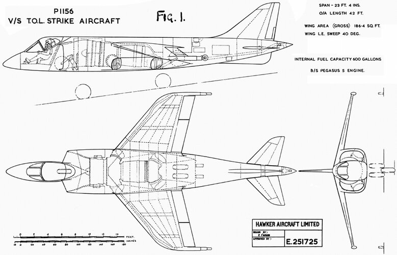
Fig 1.6 P.1156 version
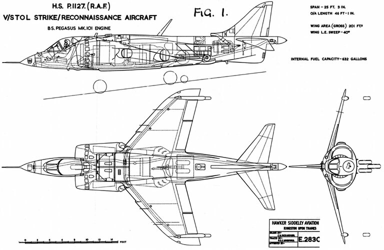
Fig 1.7 Production “Harrier”
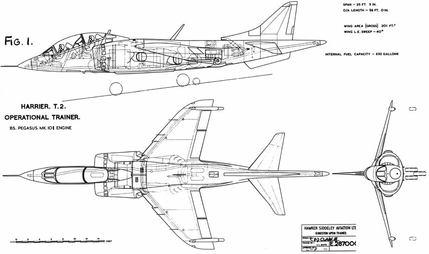
Fig 1.8 P.1127 (R.A.F.) Dual version.
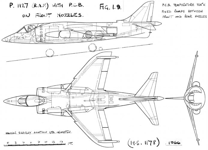
Fig 1.9 P.1127 (R.A.F.) with P.C.B.
Section 1 Subsonic VTOL aircraft with single B.S. Pegasus engine
Fig 1.1 Original P.1127 layout.
The straight through hot end is a feature which is currently being studied for supersonic STOL projects.
Fig 1.2 First Four Nozzle layout.
Fig 1.3 First Layout with Tri-cycle U/C.
The problem of the best undercarriage position is one that is still present in current projects. This particular layout was fairly simple but put the main wheels in a hot area when down and occupied a very useful fuel area when retracted.
Fig 1.4 P.1127 Prototype Aircraft
This has the quadri-cycle undercarriage layout which eventually formed the basis for the R.A.F. version of the P.1127.
Fig 1.5 Original “Kestrel”
Fig 1.6 P.1156 version
Fig 1.7 Production “Harrier”
Fig 1.8 P.1127 (R.A.F.) Dual version.
Fig 1.9 P.1127 (R.A.F.) with P.C.B.
")