- Joined
- 29 September 2006
- Messages
- 1,630
- Reaction score
- 1,034
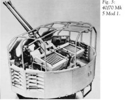
Abraham Gubler said:Some of the various Sea Slug equipped ships have horizontal loading of the launcher and some low angle and some medium angle. One thing about this solution, having a loading table that aligns the missile to the launcher, is it allows for variation in the angle needed to load the missile which may be caused by positioning the launcher onto the ship. However the two or three rail Sea Slug launchers as built could not support a very high angle (over ~45 degrees) or vertical arrangement for loading. They would need a new launcher designed for that allowing the missile to rise up through or to either side of the rotating ring of the launcher. As built in two or three rail versions the Sea Slug launcher had a large solid cradle that limited maximum elevation. See the attached picture of a scale model of the launcher.
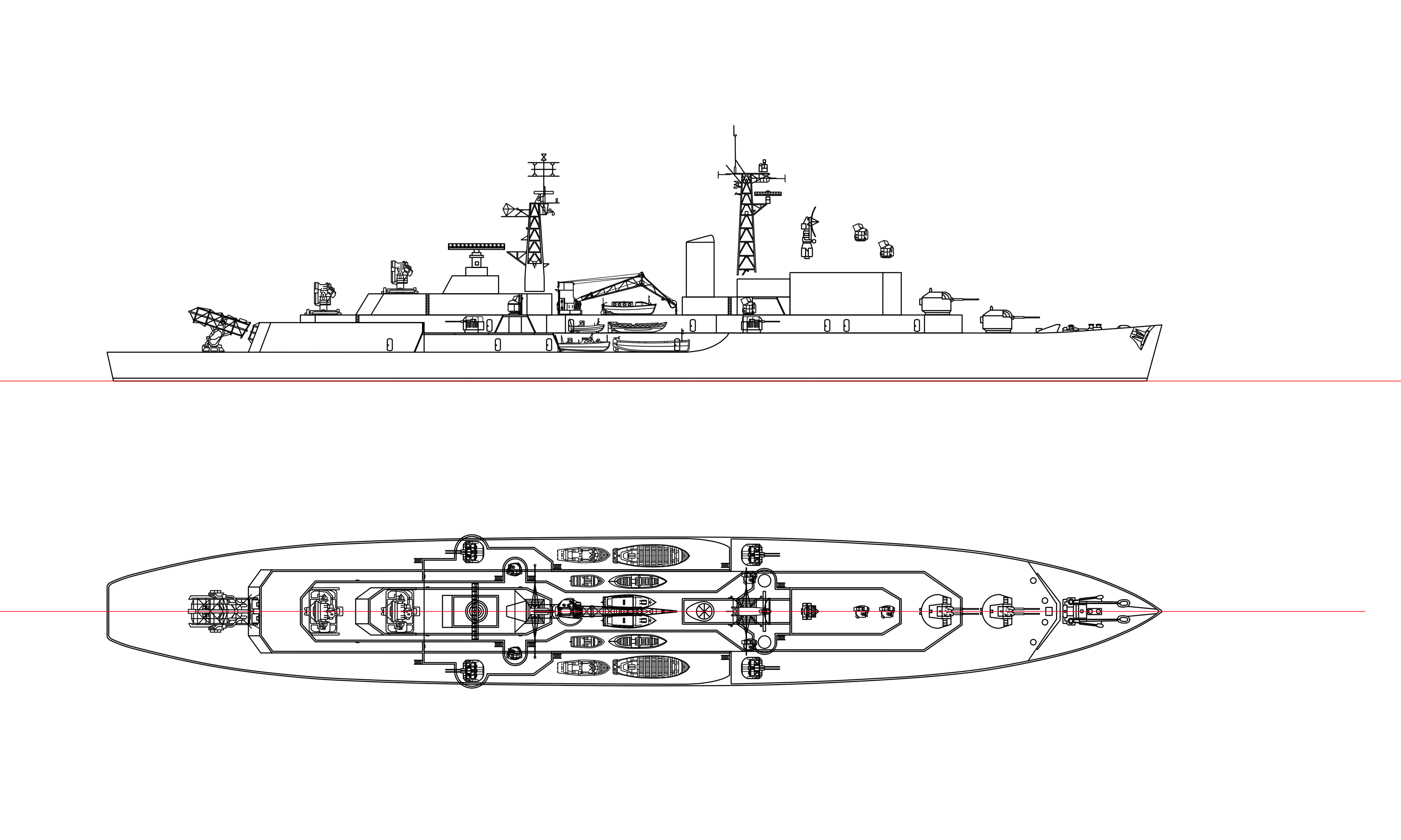
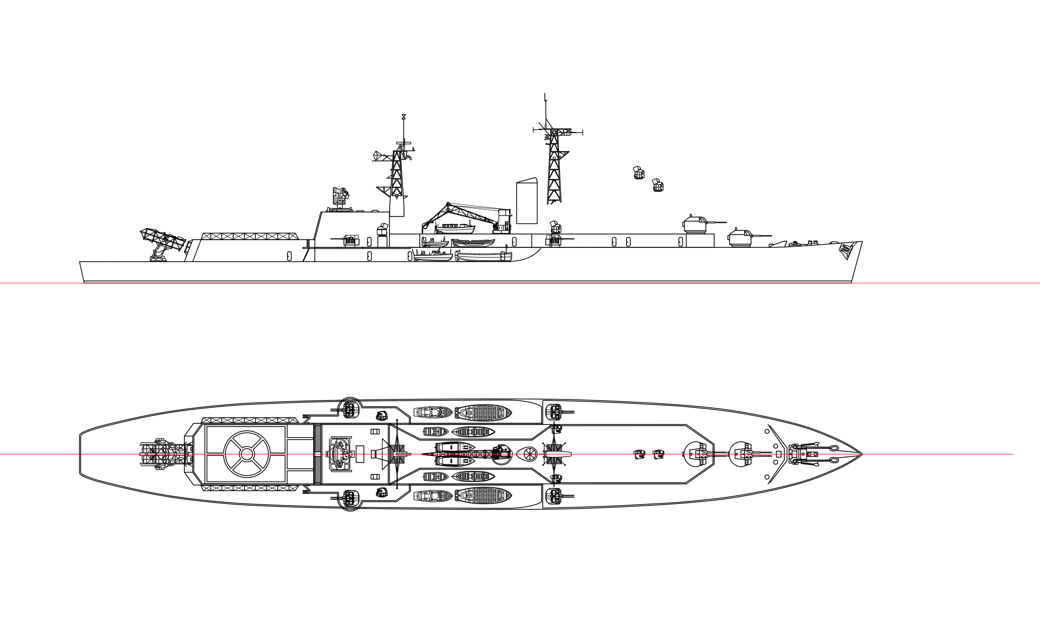
I was going by the profile plan view of Girdle Ness. I checked YouTube to see if there were any good videos of the launcher in action, and found some of launches at high elevation. There's such a launch near the start of this Pathe Video: https://m.youtube.com/watch?v=K36n3MVi4z4e]