circle-5

ACCESS: Top Secret
Top Contributor
Senior Member
Joined
31 May 2009
Messages
1,156
Reaction score
510
circle-5 said:
I believe the top "sensor carrier" is the Bell SeaPig (that's the official name -- nothing to do with the F-111B). I can't find any info on the SeaPig, including in this forum. Oink.

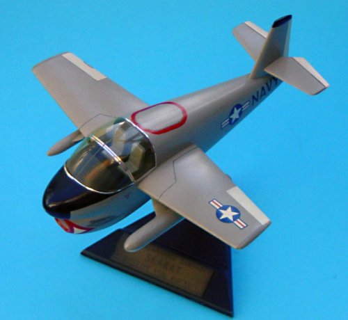
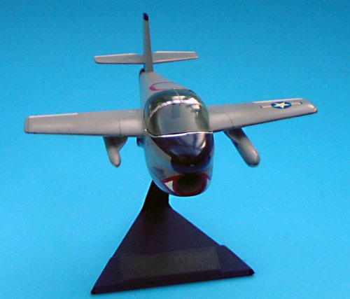
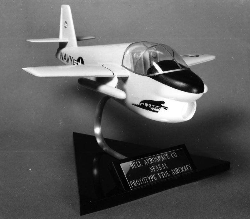
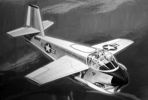
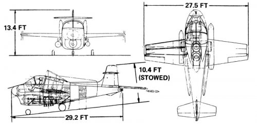
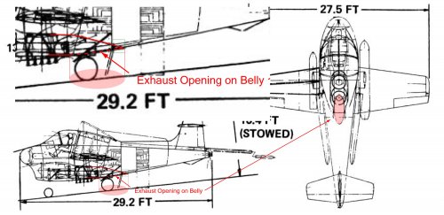
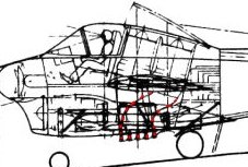
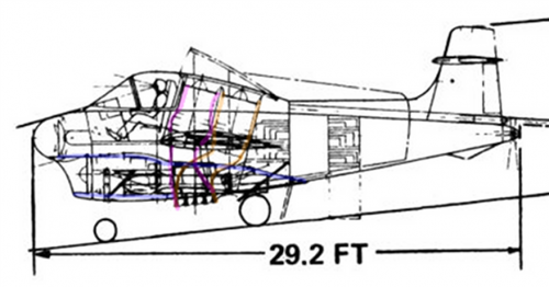
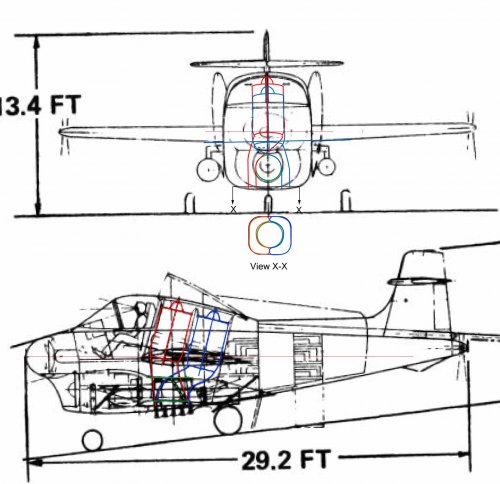
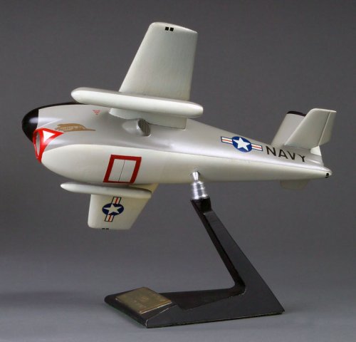
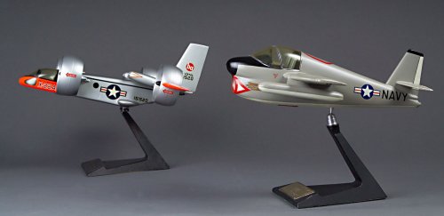
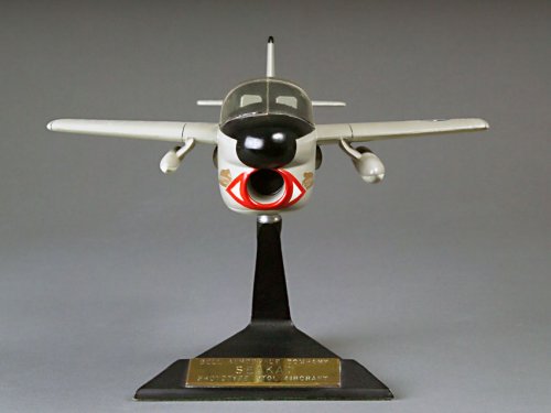
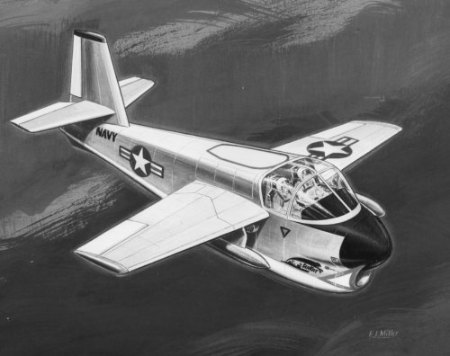
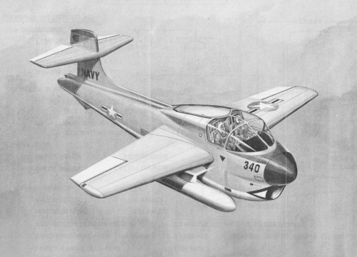
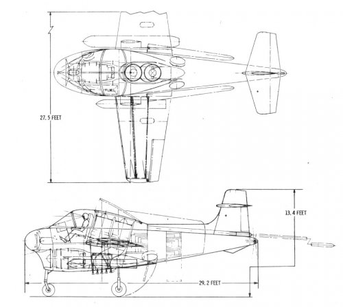
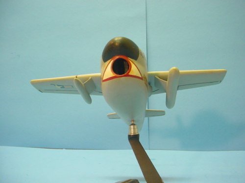
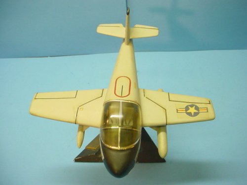
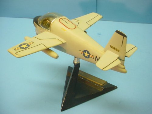
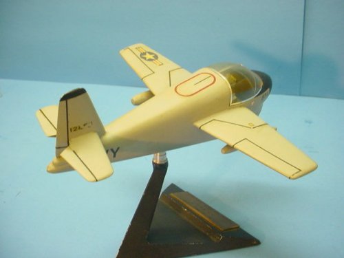
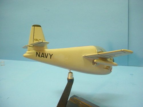
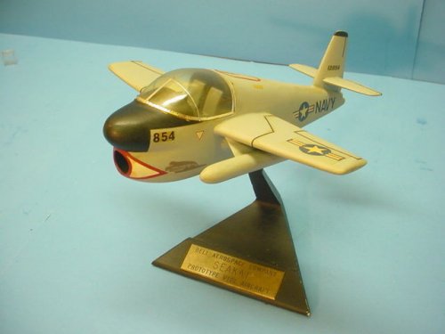
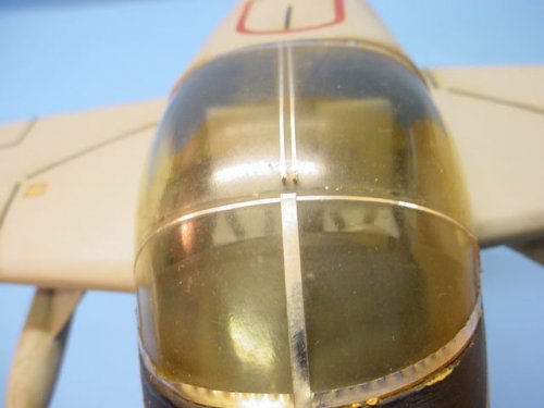
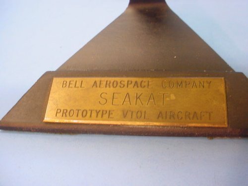
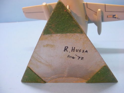
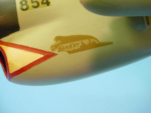
To reply no. 55 by Aerofranz, I misidentified the illustration's top sensor carrier as the Bell SeaPig. It's actually the SeaKat, still from Bell Aerospace. I apologize for the error. Attached are a couple views of a SeaKat factory model. I would be grateful for any info about this little-known aircraft.
 

Attachments

  • Bell Seakat 1 sml.jpg
    Bell Seakat 1 sml.jpg
    77.2 KB · Views: 753
  • Bell Seakat 2 sml.jpg
    Bell Seakat 2 sml.jpg
    72 KB · Views: 736
circle-5 said:
I would be grateful for any info about this little-known aircraft.

Ahem: http://up-ship.com/blog/?p=5207
image89.jpg


Also, the "X-14 derivatives" article in APR V1N3: http://www.up-ship.com/eAPR/ev1n3.htm
 
circle-5 said:
I would be grateful for any info about this little-known aircraft.

Thank you Dr. House for reminding me about APR. I feel completely ashamed, as I have all the printed issues... And to Jemiba, yes, these are swiveling nozzles: the SeaKat was a VTOL project.
 
circle-5 said:
Thank you Dr. House for reminding me about APR.

In this case, it's understandable. Somehow or other I called the "SeaKat" the "SkyKat."

It is a simplified derivative of the X-14, meant to provide a fast ASW or low-end early warning capability for ships small enough to normally only be equipped with helicopters. It used two engines for lift-only, and one engine for lift/cruise. Payload would typically be only single weapon such as a torpedo or Bullpup missile.
 
"..yes, these are swiveling nozzles"
Wasn't sure, as the dorsal hatches are nearly in the same region,
could have meant pure lift engines.

"Ahem: http://up-ship.com/blog/?p=5207"
The good old feeling from schooltime, you ask the teacher, he tells you, that
this question already was dealt with the day before ... :-[
 
Well they appear to be swiveling, to me anyway, just looking at the model. And as a derivative of the X-14, you'd think these nozzles would swivel, but maybe not. They could very well be fixed-angle ducts -- not the most elegant solution, with the unnecessary back pressure of two deflection offsets: lateral and down. If the aircraft's general appearance is an indicator, elegance wasn't at the top of Bell's priority list for the SeaKat anyway, though it could have been a great asset if scattered on SCS and smaller Navy vessels as intended.
 
This diagram is a bit cluttered, but it looks to me as if there is one exhaust duct with two fixed exits. The vertical jets share the same exhaust duct with the horizontal jet, and for vertical thrust the louvers are opened directly beneath the VTO jets, and a valve is closed on the aftmost horizontal duct. For horizontal thrust, the VTO engines are shut down, the valve is opened and the louvers closed. The diagram doesn't seem to show swivelling nozzles on the fuselage sides, but the models and art do seem to. My guess is that these might be more "fine control" nozzles than actual thrusting nozzles.
 

Attachments

  • Image10.jpg
    Image10.jpg
    38.7 KB · Views: 854
  • Image11.jpg
    Image11.jpg
    57.1 KB · Views: 922
Orionblamblam said:
This diagram is a bit cluttered...

Yes, but it does help make sense of the combined thrust chamber, with its valves and louvers. VTOL was never uncomplicated...
Thank you for posting.
 
Tailspin Turtle said:
Here's what I'm pretty sure of after a close examination of the drawing...

Not sure I entirely agree with your police work there, Lou. I think you've nailed the horizontal thrust component, but I'm pretty sure the below shows the vertical thrust component.

Circle-5: does an examination of the model belly provide any insight? If my understanding of the setup is correct, there should be a round or square feature - perhaps painted on or decal - with parallel lines where I've posited the vertical thruster, and an elliptical feature - paint, decal or recessed - where the horizontal thruster would seem to be.
 

Attachments

  • vto.jpg
    vto.jpg
    31.9 KB · Views: 1,845
Orionblamblam said:
Tailspin Turtle said:
Here's what I'm pretty sure of after a close examination of the drawing...

Not sure I entirely agree with your police work there, Tommy. I think you've nailed the horizontal thrust component, but I'm pretty sure the below shows the vertical thrust component.

I was only trying to show the horizontal thrust because of the speculation about the swiveling nozzles. Also note with respect to your sketch that there are two different exhaust pipes leading down to the belly and I pretty sure some sort of diverter valve was present at that location to add the horizontal engine thrust to the vertical thrust at the cg.
 
Tailspin Turtle said:
Also note with respect to your sketch that there are two different exhaust pipes leading down to the belly...

One of the difficulties I have with the diagram is that is *seems* to only show an exhaust duct for the aft VTO engine. The forward engine doesn't seem to have anywhere to go, unless it's a *really* thin manifold with an immediate 90-degree bend. Bleah.

and I pretty sure some sort of diverter valve was present at that location to add the horizontal engine thrust to the vertical thrust at the cg.

Agreed.
 
Orionblamblam said:
Circle-5: does an examination of the model belly provide any insight? If my understanding of the setup is correct, there should be a round or square feature - perhaps painted on or decal - with parallel lines where I've posited the vertical thruster, and an elliptical feature - paint, decal or recessed - where the horizontal thruster would seem to be.
That's about it: there is a bottom rectangular-ish red outline indicating where the VTOL thrust is supposed to exhaust. Nothing fancy like doors or louvers. The horizontal exhaust detail is either worn off or left to the imagination. I'll get a bottom view of the model posted one of these days. I concur the thrust of all three engines would have been combined for VTO, with any number of valves, vanes and vectoring devices directly inside the internal hot exhaust box. This arrangement is far more elaborate than I ever imagined. Wasn't the Pegasus engine available back then?
 
Don't know how they were going to mix the two vertical engines' exhaust. And with the horizontal engine exhaust pipe passing through there as well, it certainly gets complicated.
 

Attachments

  • vtol_kat_what.png
    vtol_kat_what.png
    207.3 KB · Views: 228
Good work so far. Here's my guess. I'm hoping Scott knows what the horizontal thrust engine diverter might look like...
 

Attachments

  • SeaKat Vertical Lift System web.jpg
    SeaKat Vertical Lift System web.jpg
    209.1 KB · Views: 435
Based on that drawing, it looks to me like the third horizontal engine exhausts out of the belly right between the main landing gear. It also look like there is a nozzle at the end of the engine that can vector the thrust almost horizontally back out the gutter like shape between the main gear and possibly vector it louver style straight down down as well.

I think the way TT has the lift engines exhausting out either side of the cruise engine is correct. At least it makes sense, anyway.
 
Here is a view of the SeaKat model underside. Note puffer exhausts on wingtips and at rear of fuselage. Hope that helps.
 

Attachments

  • Bell SeaKat Underside sml.jpg
    Bell SeaKat Underside sml.jpg
    83.2 KB · Views: 375
Bell VTOL beauty contest. If you think Rosie O'Donnell is sexy, the SeaKat wins.
 

Attachments

  • Bell X-22A & SeaKat.jpg
    Bell X-22A & SeaKat.jpg
    98.5 KB · Views: 424
circle-5 said:
Here is a view of the SeaKat model underside. Note puffer exhausts on wingtips and at rear of fuselage. Hope that helps.

That looks like a variation on the exhaust location for the inline engine from the drawing provided earlier although it is consistent with the artists concept provided along with the drawing. (In both the artists concept and the model, the location of the pylons for the external stores is different than the drawing and the SeaKat represented does not have the dorsal fin of the drawing.) Note that a reposition upward of the inline engine would be required to position the Harrier-type swivel nozzles there or its exhaust would have to be ducted upward as well as outboard.
 
Boo!
 

Attachments

  • Bell SeaKat Front.jpg
    Bell SeaKat Front.jpg
    71.4 KB · Views: 362
John, cool! Thank you very much for that awesome X-32 and DP-2 contender for 'I have the ugliest face' aircraft contest!
 
Sure looks like a cartoon character. Guess the crewmen would have nicknamed it "Droopy" or "Mickey Mouse", or something to that effect...

@Flateric: NOTHING can beat the DP-2!!!
(this being said, I think it derived from the X-14C design, the same Bell design that spawned the SeeKat...).
 
Did they headhunt staff from Blackburn Aircraft of Brough as it has all the hallmarks of most of their projects - Butt Ugly ! ;D.
 
circle-5 said:
Ahhemm... This picture RIGHT here clearly shows that this project had NO chance of Navel acceptance what-so-ever!

NO naval pilot with ANY sense of "future-career" status would willingly climb into an aircraft that's frontal "view" gave anyone and everyone the sense of a lipstick-coated hooker about to take a nose dive on a john! :)

Randy
 
RanulfC said:
circle-5 said:
Ahhemm... This picture RIGHT here clearly shows that this project had NO chance of Navel acceptance what-so-ever!

NO naval pilot with ANY sense of "future-career" status would willingly climb into an aircraft that's frontal "view" gave anyone and everyone the sense of a lipstick-coated hooker about to take a nose dive on a john! :)

Randy


You're right. Should have pitched it to the Air Force. :D
 
I just noticed several major differences between some of the pictures Scott posted, notably in the areas of horizontal tail vertical location, wing fold, and weapons pylons.
Scott's three view shows wings folding back along the fuselage, the fold being pretty much at the root, and fuselage mounted pylons. On the other hand, the table model shows folds just outboard of the wing pylons. I wonder which iteration came first. Either way, getting bleed air to the wingtip puffers through a wingfold would have been pretty tough, IMHO. Does anyone know of VTOL aircraft designed with that feature?
 
Bell Seakat model circa 1972 found on eBay.

URL:
http://www.ebay.com/itm/Vintage-1972-BELL-AEROSPACE-X-14-SEAKAT-PROTOTYPE-VTOL-AIRCRAFT-DESKTOP-MODEL-/141119181812?pt=Model_Kit_US&hash=item20db5bd3f4
 

Attachments

  • $_34H.JPG
    $_34H.JPG
    26.5 KB · Views: 125
  • $_34G.JPG
    $_34G.JPG
    28.2 KB · Views: 97
  • $_34F.JPG
    $_34F.JPG
    28.1 KB · Views: 91
  • $_34E.JPG
    $_34E.JPG
    30.2 KB · Views: 269
  • $_34D.JPG
    $_34D.JPG
    29.1 KB · Views: 269
  • $_34C.JPG
    $_34C.JPG
    28.3 KB · Views: 267
  • $_34B.JPG
    $_34B.JPG
    26.4 KB · Views: 281
  • $_34A.JPG
    $_34A.JPG
    30.1 KB · Views: 286
Bell Seakat model circa 1972 found on eBay.
 

Attachments

  • $_34I.JPG
    $_34I.JPG
    31.6 KB · Views: 82
  • $_34J.JPG
    $_34J.JPG
    30.9 KB · Views: 75
  • $_34K.JPG
    $_34K.JPG
    32.6 KB · Views: 79
  • $_34L.JPG
    $_34L.JPG
    29.8 KB · Views: 116
A little bit of background on the project, via the 'Rockwell NR-356 Sea Control Ship (SCS) V/STOL fighter (XFV-12A)' thread:
According to George Spangenberg, Evaluation Division Director of NAVAIR, the push for the XFV-12 came from NAVMAT. Specifically from Rear Admiral Thomas Davies head of R&D at NAVMAT, who felt that the Navy's frigates and destroyers could not do the ASW mission, and small carriers with ASW helos could get the job done. Naturally, said carriers would need air defense if they were going to operate on their own, AEGIS being nearly a decade away, and in 1972, in an unprecendented move by NAVMAT, feelers were sent out to the aerospace industry for a VTOL long range senor aircraft and a high perfomance VTOL fighter. A wide variety of proposals from the industry came back, and NAVMAT had NAVAIR review them. The submissions were all over the place, ex C-130 variant, because the Sea Control Ship was so poorly defined. As you mentioned before a lot of squids were worried that a supplement such as the SCS would end up being shoehorned in as the main type of carriers due to budgetary concerns.
 
Back
Top Bottom